
Related Manuals for Advantech ADAM-4572


Summary of Contents for Advantech ADAM-4572
- Page 1 User Manual ADAM-4572, EKI-1221,EKI-1222, EKI-1224, EKI-1221D, EKI-1222D 1/2/4-port Modbus Gateway...
- Page 2 No part of this manual may be reproduced, copied, translated or transmitted in any form or by any means without the prior written permission of Advantech Co., Ltd. Information provided in this manual is intended to be accurate and reliable. How- ever, Advantech Co., Ltd.
-
Page 3: Declaration Of Conformity
This product has passed the CE test for environmental specifications when shielded cables are used for external wiring. We recommend the use of shielded cables. This kind of cable is available from Advantech. Please contact your local supplier for ordering information. -
Page 4: Safety Instructions
The sound pressure level at the operator's position according to IEC 704-1:1982 is no more than 70 dB (A). DISCLAIMER: This set of instructions is given according to IEC 704-1. Advantech disclaims all responsibility for the accuracy of any statements contained herein. -
Page 5: Table Of Contents
2.3.1 LED Indicators ................12 Table 2.2: EKI-1221/1222/1224, EKI-1221D/1222D LED Indica- tors................12 Table 2.3: ADAM-4572 LED Indicators ........12 2.3.2 Dimensions (Units: mm).............. 13 Figure 2.3 Front View of EKI-1221 ..........13 Figure 2.4 Side View of EKI-1221..........13 Figure 2.5 Back View of EKI-1221.......... - Page 6 Figure 2.35EKI-122X series Serial Port Pin Assignments..29 2.4.4 Connecting to a Host or the Network.......... 30 2.4.5 ADAM-4572 Serial Port Wiring ........... 30 Figure 2.36Wiring RS-232 Connection........30 Figure 2.37Wiring RS-485 Connection........31 Figure 2.38Wiring RS-422 Connection........31 Chapter Configuration ........
-
Page 7: Chapter 1 Introduction
Chapter Introduction... -
Page 8: Overview
Ethernet and Serial Modbus devices. The ADAM-4572 and EKI-122X series provides one, two or four serial ports, one or two Ethernet ports, a wide range of power inputs, and a compact slim design, making them an ideal solution for connecting multiple Modbus/ RTU and Modbus/ASCII serial devices to Modbus TCP (Ethernet). -
Page 9: Package Check List
1 x OPT1-DB9-AE (DB9 to terminal connector) 1 x DIN-rail kit 2 x Wall/panel mount kit Note! Please check above items, if any one of them is missing or damaged, contact your sales representative. 3 ADAM-4572 & EKI-122X Series User Manual... - Page 10 ADAM-4572 & EKI-122X Series User Manual...
-
Page 11: Chapter 2 Getting Started
Chapter Getting Started... -
Page 12: Understanding Modbus Gateways
PC or control panel. Advantech’s revolutionary network-enabling technology is now allowing control devices with serial ports to connect to the Ethernet and share networks quickly and cost-effectively. The ADAM-4572 and EKI-122X series are network-based, Modbus gateways for integrating new and existing Modbus/RTU and Modbus/ASCII serial devices to newer TCP/IP networked-based devices. -
Page 13: Figure 2.1 Modbus System Architecture 1
The basic system architecture is as below: Figure 2.1 Modbus System Architecture 1 Figure 2.2 Modbus System Architecture 2 7 ADAM-4572 & EKI-122X Series User Manual... -
Page 14: Modbus Rtu
Modbus/TCP enables the use of Modbus messaging in an Intranet running the TCP/ IP protocols. Modbus/TCP is most commonly used for Ethernet attachment of PLC’s or I/O modules to other simple field buses or I/O networks. ADAM-4572 & EKI-122X Series User Manual... -
Page 15: Specifications
No. of Power Inputs 2 Power Connector Terminal block Power Consumption 300 mA (max.) Environment Operating Temperature 0 to 60 °C (32 to 140 °F) Storage Temperature -20 to 85 °C (-4 to 185 °F) 9 ADAM-4572 & EKI-122X Series User Manual... -
Page 16: Eki-1221D/1222D
12 to 48 VDC Power Connector Terminal block Power Consumption 300 mA (max.) Environment Operating Temperature 0 to 60 °C (32 to 140 °F) Storage Temperature -20 to 80 °C (-4 to 176 °F) ADAM-4572 & EKI-122X Series User Manual... -
Page 17: Adam-4572
10 to 30 VDC Power Connector Terminal block Power Consumption 150 mA (max.) Environment Operating Temperature 0 to 60 °C (32 to 140 °F) Storage Temperature -20 to 80 °C (-4 to 176 °F) 11 ADAM-4572 & EKI-122X Series User Manual... -
Page 18: Hardware
There are LEDs display the two sets of power status, system status, dual networks status, and serial communication status on the front panel of ADAM-4572 and .EKI- 122X series. Each of them has its own specific meaning as below table. -
Page 19: Dimensions (Units: Mm)
2.3.2 Dimensions (Units: mm) EKI-1221: Figure 2.3 Front View of EKI-1221 Figure 2.4 Side View of EKI-1221 13 ADAM-4572 & EKI-122X Series User Manual... -
Page 20: Figure 2.5 Back View Of Eki-1221
Figure 2.5 Back View of EKI-1221 Figure 2.6 Top View of EKI-1221 ADAM-4572 & EKI-122X Series User Manual... -
Page 21: Figure 2.7 Front View Of Eki-1222
EKI-1222: Figure 2.7 Front View of EKI-1222 Figure 2.8 Side View of EKI-1222 15 ADAM-4572 & EKI-122X Series User Manual... -
Page 22: Figure 2.9 Back View Of Eki-1222
Figure 2.9 Back View of EKI-1222 Figure 2.10 Top View of EKI-1222 ADAM-4572 & EKI-122X Series User Manual... -
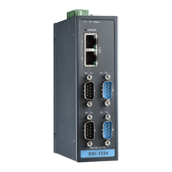
Page 23: Figure 2.11Front View Of Eki-1224
EKI-1224: Figure 2.11 Front View of EKI-1224 Figure 2.12 Side View of EKI-1224 17 ADAM-4572 & EKI-122X Series User Manual... -
Page 24: Figure 2.13Back View Of Eki-1224
Figure 2.13 Back View of EKI-1224 Figure 2.14 Top View of EKI-1224 ADAM-4572 & EKI-122X Series User Manual... -
Page 25: Figure 2.15Front View Of Eki-1221D
EKI-1221D: Figure 2.15 Front View of EKI-1221D Figure 2.16 Side View of EKI-1221D 19 ADAM-4572 & EKI-122X Series User Manual... -
Page 26: Figure 2.17Back View Of Eki-1221D
Figure 2.17 Back View of EKI-1221D Figure 2.18 Top View of EKI-1221D ADAM-4572 & EKI-122X Series User Manual... -
Page 27: Figure 2.19Front View Of Eki-1222D
EKI-1222D: Figure 2.19 Front View of EKI-1222D Figure 2.20 Side View of EKI-1222D 21 ADAM-4572 & EKI-122X Series User Manual... -
Page 28: Figure 2.21Back View Of Eki-1222D
Figure 2.21 Back View of EKI-1222D Figure 2.22 Top View of EKI-1222D ADAM-4572 & EKI-122X Series User Manual... -
Page 29: Figure 2.23Front View Of Adam-4572
ADAM-4572 Figure 2.23 Front View of ADAM-4572 Figure 2.24 Back View of ADAM-4572 23 ADAM-4572 & EKI-122X Series User Manual... -
Page 30: Figure 2.25Bottom View Of Adam-4572
Figure 2.25 Bottom View of ADAM-4572 Figure 2.26 Side View of ADAM-4572 ADAM-4572 & EKI-122X Series User Manual... -
Page 31: Connecting Hardware
Fixed to a DIN-rail Panel/Wall Mounting The ADAM-4572 and EKI-122X serie can be attached to a wall using the included metal brackets. Each bracket comes with four screws. You can install the Modbus Gateways firmly via the components, please see the figures below. -
Page 32: Figure 2.28Adam-4572 Panel Mounting Bracket Dimensions
Figure 2.28 ADAM-4572 Panel Mounting Bracket Dimensions Figure 2.29 ADAM-4572 Panel Mounting ADAM-4572 & EKI-122X Series User Manual... -
Page 33: Figure 2.30Din-Rail Step 1
The ADAM-4572, EKI-122X series can be mounted on a standard DIN-rail. The DIN- rail kit is screwed on the Modbus data gateway when out of factory. If the DIN-rail kit is not screwed on the ADAM-4572, EKI-122X series, please screw the DIN-rail kit on the Modbus data gateway first. -
Page 34: Figure 2.32Din-Rail Adapter
Figure 2.32 DIN-rail Adapter Figure 2.33 DIN-rail Mounting ADAM-4572 & EKI-122X Series User Manual... -
Page 35: Connecting Power
The EKI-122X series provides one, two or four standard serial ports DB9 (male) connectors. RS-232/422/485 pin assignments are as below. Figure 2.35 EKI-122X series Serial Port Pin Assignments RS-232 RS-422 RS-485 Data- Data+ 29 ADAM-4572 & EKI-122X Series User Manual... -
Page 36: Connecting To A Host Or The Network
Series can be connected to other hubs or switches through a twisted-pair straight through the Ethernet cable. For configuration or troubleshooting purposes, user may need to connect the ADAM-4572 and EKI-122X Series directly to the host PC. In this operation mode, user can use a crossover Ethernet cable to connect the ADAM-4572 and EKI-122X Series to the host PC’s Ethernet connector. -
Page 37: Figure 2.37Wiring Rs-485 Connection
Wiring for RS-485 Connection Figure 2.37 Wiring RS-485 Connection Wiring for RS-422 Connection Figure 2.38 Wiring RS-422 Connection 31 ADAM-4572 & EKI-122X Series User Manual... - Page 38 ADAM-4572 & EKI-122X Series User Manual...
-
Page 39: Configuration
Chapter Configuration... -
Page 40: Installing The Configuration Utility
Installing the Configuration Utility The following section will show you how to install Advantech Serial Device Server Configuration Utility, a tool to set up and monitor the Modbus Gateways. Note Be sure the Microsoft .NET Framework on your host PC is greater than version 2.0 . - Page 41 5. Carefully read the Software License Agreement, and press "I Agree" to continue. 6. The InstallShield will specify a default installation path, C:\Program Files\Advantech eAutomation\Serial Device Server Configuration Utility. 35 ADAM-4572 & EKI-122X Series User Manual...
- Page 42 7. After few minutes, a message will indicate that Configuration Utility is suc- cessfully installed, click “Finish” to exit the InstallShield. ADAM-4572 & EKI-122X Series User Manual...
-
Page 43: Starting The Configuration Utility
PC to enhance network security. With this secure function enabled, other PCs will not have permission for configuration. After the installation program on the Advantech IEDG Series Driver Utility CD-ROM is finished, the serial device servers will be ready for use and config- ure. -
Page 44: Discovering Modbus Gateways
3.3.1 Auto Searching Advantech Serial Device Server Configuration Utility will automatically search all the EKI, ADAM and EDG series device servers on the network and show them on the Serial Device Server List Area of the utility. The Utility provides an auto-searching function to show your device(s) by simply executing the configuration utility program from the Start Menu. - Page 45 Click on the “+” before the device name, and the utility will expand the communication interfaces on this Modbus data gateway. Click on each interface item, you will entry the configuration page to modify the set- ting. The configuration will be introduced on following sections. 39 ADAM-4572 & EKI-122X Series User Manual...
- Page 46 ADAM-4572 & EKI-122X Series User Manual...
-
Page 47: Clear Device List And Search Again
Using “Add IP address to Favorite” or “Search a Range of IP addresses” functions, you are allowed to add one device or group of devices to “Favorites”. These devices can locate on local network domain or other network domain. 41 ADAM-4572 & EKI-122X Series User Manual... -
Page 48: Setting Ethernet Parameters
And clink on the “+” before the device name, and utility will expand the communication interfaces on this Modbus data gateway. Select the Ethernet interface (Eth1 or Eth2, these are two individual Ethernet ports). ADAM-4572 & EKI-122X Series User Manual... -
Page 49: Setting Serial Communication Parameters
IP Address, Subnet Mask, Default Gateway: The IP address identifies your Modbus data gateway on the global network. Each ADAM-4572, EKI-122X series has the same default IP address 10.0.0.1 and 10.0.0.2 for dual Ethernet ports. Obtain these specific IP addresses from your network admin- istrator and then configure each Advantech Modbus gateway with individual IP addresses, related Subnet Mask and Gateway Setting. -
Page 50: Basic Configuration
Baud Rate: The EKI-122X series supports baud rate from 50 bps to 921.6 Kbps. While setting the baud rate, please note that the value should conform to the current transmission speeds of connected devices. ADAM-4572 & EKI-122X Series User Manual... - Page 51 None Even or Odd Data bits Stop bits Modbus/ASCII Parity None Even or Odd Data bits Stop bits Modbus/RTU Flow Control: The EKI-122X series provides four options: None, XOn/XOff, RTS/CTS, and DTR/ DSR. 45 ADAM-4572 & EKI-122X Series User Manual...
-
Page 52: Operation Configuration
ASCII Character Timeouts (ms): This option specifies the time interval in milliseconds between characters within the Modbus/ASCII message. If a greater interval occurs, the receiving device assumes an error has occurred. ADAM-4572 & EKI-122X Series User Manual... - Page 53 512 to 50000. Note that a port number below 512 is already reserved in each situation for other specific uses and unavail- able for your selection. 47 ADAM-4572 & EKI-122X Series User Manual...
- Page 54 Modbus/RTU or Modbus ASCII. After the timeout is expired and no response is received, the EKI-122X series will regard the command as failed. ADAM-4572 & EKI-122X Series User Manual...
-
Page 55: Function Accessible Setting
Specified IP which can access: Type the IP address in the column and click “Add” or “Delete” button to make the accessible IP address list. The limit of this list is 32 IP addresses. 49 ADAM-4572 & EKI-122X Series User Manual... -
Page 56: Monitoring Modbus Status
The configuration utility provides several administrator settings for easy management and configuration. Right click the mouse on the device name in the sub-tree of Serial Device Sever List Area, and select these administrator settings. ADAM-4572 & EKI-122X Series User Manual... -
Page 57: Import/Export Serial Port Setting
If there are many Modbus data gateways need your management, you may need to identify which unit is correct to configuration on utility. Click “Locate” to make that unit’s “Status” LED be steady on until you click “Stop Locate”. 51 ADAM-4572 & EKI-122X Series User Manual... -
Page 58: Lock Device
If you forgot the password, the only way to solve this problem is to restore the setting of the Modbus data gateway to the factory default which will be introduced next section. ADAM-4572 & EKI-122X Series User Manual... -
Page 59: Restore To Factory Default Settings
Then, please power off the Modbus data gateway within ten seconds, after recon- necting the power back, the all setting will be reset to the factory default. If the power remains more than ten seconds, the Modbus data gateway will not have any changes. 53 ADAM-4572 & EKI-122X Series User Manual... -
Page 60: Update Firmware
3.8.5 Update Firmware Advantech continually upgrades its firmware to keep up with the ever-expending world of computing. You can use the update firmware function in the utility to carry upgrade procedure. Please access Advantech’s website: to download the latest version of the firmware. - Page 61 Select the firmware file you want to update. After downloading the firmware completely, click “OK” button, and the Modbus data gateway will restart automatically. 55 ADAM-4572 & EKI-122X Series User Manual...
- Page 62 No part of this publication may be reproduced in any form or by any means, electronic, photocopying, recording or otherwise, without prior written permis- sion of the publisher. All brand and product names are trademarks or registered trademarks of their respective companies. © Advantech Co., Ltd. 2010...
Need help?
Do you have a question about the ADAM-4572 and is the answer not in the manual?
Questions and answers