Advantech EKI-1222 User Manual
Eki-122x series
1/2/4-port modbus gateway
Hide thumbs
Also See for EKI-1222:
- User manual (80 pages) ,
- User manual (62 pages) ,
- User manual (56 pages)
Table of Contents
Advertisement
Quick Links
Advertisement
Table of Contents

Related Manuals for Advantech EKI-1222


Summary of Contents for Advantech EKI-1222
- Page 1 User Manual EKI-122X Series 1/2/4-port Modbus Gateway...
- Page 2 No part of this manual may be reproduced, copied, translated or transmitted in any form or by any means without the prior written permission of Advantech Co., Ltd. Information provided in this manual is intended to be accurate and reliable. How- ever, Advantech Co., Ltd.
-
Page 3: Declaration Of Conformity
This product has passed the CE test for environmental specifications when shielded cables are used for external wiring. We recommend the use of shielded cables. This kind of cable is available from Advantech. Please contact your local supplier for ordering information. -
Page 4: Packing List
Before setting up the system, check that the items listed below are included and in good condition. If any item does not accord with the table, please contact your dealer immediately. 1 x EKI-1221 or EKI-1222 or EKI-1224 Modbus Gateway 1 x Terminal Block ... - Page 5 The openings on the enclosure are for air convection. Protect the equipment from overheating. DO NOT COVER THE OPENINGS. Make sure the voltage of the power source is correct before connecting the equipment to the power outlet. Position the power cord so that people cannot step on it. Do not place anything over the power cord.
-
Page 6: Table Of Contents
LED Indicators ................13 Figure 2.9 System LED Panel ..........13 2.3.5 Dimensions ................. 14 Figure 2.10 EKI-1221 and EKI-1222 Dimensions...... 14 Figure 2.11 EKI-1224 Dimensions..........15 Connecting Hardware ................16 2.4.1 Choosing a Location ..............16 Figure 2.12 Installing the DIN-Rail Mounting Kit......16 Figure 2.13 Removing the DIN-Rail........... - Page 7 Figure 3.7 View > Settings > Main Form Setting ..... 28 Figure 3.8 View > Settings > Device Manager ......29 3.4.2 Discovering Your Device Server ..........30 Figure 3.9 Open View of Serial Device Configuration Utility..30 Figure 3.10 Selecting a Group........... 31 Figure 3.11 Selecting a Device..........
- Page 8 Figure 4.14 Syslogd > Syslogd Setting ........55 4.8.2 Syslogd Message ............... 55 Figure 4.15 Syslogd > Syslogd Message ........55 4.8.3 Modbus IP Mapping..............55 Figure 4.16 Syslogd > Modbus IP Mapping ......55 4.8.4 Modbus Port Mapping..............56 Figure 4.17 Syslogd >...
-
Page 9: Introduction
Chapter Introduction... -
Page 10: Overview
Overview Advantech’s EKI-1221/EKI-1222/EKI-1224 series of Modbus Gateways (the following manual will use EKI-122X series instead of complete model name) are a robust, fea- ture-rich, and cost effective way to integrate Ethernet and Serial Modbus devices. The EKI-122X series provides one, two or four serial ports, two Ethernet ports, a wide... -
Page 11: Getting Started
Chapter Getting Started... -
Page 12: Understanding Modbus Gateways
Networks have become increasingly vital for industrial automation applications. Many control devices today do not have a network port and can only communicate with a dedicated local PC or control panel. Advantech’s revolutionary network-enabling technology is now allowing control devices with serial ports to connect to the Ethernet and share networks quickly and cost-effectively. -
Page 13: Modbus Rtu
The basic system architecture is as below: Modbus / TCP Master Device Host (PC) P1 P2 Default Status EKI 1222 P1 P2 Status Default EKI 1221 Figure 2.1 Modbus System Architecture 1 P1 P2 Status Default Figure 2.2 Modbus System Architecture 2 2.1.2 Modbus RTU The Modbus/RTU protocol defines how a “master”... -
Page 14: Modbus Ascii
EKI-1221I: 2 x RJ45 + 1 x RS-232/422/485 EKI-1221CI: 2 x RJ45 + 1 x RS-422/485 EKI-1222: 2 x RJ45 + 2 x RS-232/422/485 EKI-1222I: 2 x RJ45 + 2 x RS-232/422/485 EKI-1222CI: 2 x RJ45 + 2 x RS-422/485 ... - Page 15 , redundant dual inputs Software OS Support 32-bit/64-bit Windows XP/Vista/7/8/8.1, Windows Server 2003/2008/2008 R2/2012/2012 R2, and Linux Utility Advantech EKI Device Configuation Utility Operation Modes Modbus RTU Master/Slave mode Modbus ASCII Master/Slave mode Configuration Windows utility, Web Browser Management SNMP MIB-II...
-
Page 16: Hardware
Hardware 2.3.1 Front View The following view shows the EKI-1221. P2 Status Default EKI-1221 Figure 2.3 Front View No. Item Description System LED panel See “LED Indicators” on page 13 for further details. Default button Press for at least 10 secs. to rest device to default settings. ETH port RJ45 ports x 2 Serial port... -
Page 17: Figure 2.4 Front View
The following view shows the EKI-1222. P2 Status Default EKI-1222 Figure 2.4 Front View No. Item Description System LED panel See “LED Indicators” on page 13 for further details. Default button Press for at least 10 secs. to rest device to default settings. -
Page 18: Figure 2.5 Front View
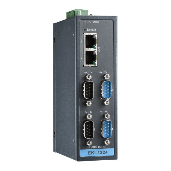
The following view shows the EKI-1224. P2 Status Default Serial ports EKI-1224 Figure 2.5 Front View No. Item Description System LED panel See “LED Indicators” on page 13 for further details. Default button Press for at least 10 secs. to rest device to default settings. ETH port RJ45 ports x 2 Serial port... -
Page 19: Rear View
2.3.2 Rear View The following view shows the EKI-1221 and EKI-1222. Figure 2.6 Rear View No. Item Description DIN-Rail mounting Mounting plate used for the installation to a standard DIN rail plate EKI-122X Series User Manual... -
Page 20: Top View
The following view shows the EKI-1224. Figure 2.7 Rear View No. Item Description DIN-Rail mounting Mounting plate used for the installation to a standard DIN rail plate 2.3.3 Top View Figure 2.8 Top View No. Item Description Ground terminal Screw terminal used to ground chassis Terminal block Connect cabling for power and alarm wiring Wall mounting holes Screw holes (top x4, bottom x4) used in the installation of a wall... -
Page 21: Led Indicators
2.3.4 LED Indicators P1 P2 Status Figure 2.9 System LED Panel No. LED Name LED Color Description Green Power 1 is on Power 1 is off, or power error condition exists Green Power 2 is on Power 2 is off, or power error condition exists Status Amber The device server has been located by utility’s loca-... -
Page 22: Dimensions
2.3.5 Dimensions The following view shows the EKI-1221 and EKI-1222. 36.60 30.50 Figure 2.10 EKI-1221 and EKI-1222 Dimensions EKI-122X Series User Manual... -
Page 23: Figure 2.11 Eki-1224 Dimensions
The following view shows the EKI-1224. 48.65 30.50 Figure 2.11 EKI-1224 Dimensions EKI-122X Series User Manual... -
Page 24: Connecting Hardware
Connecting Hardware 2.4.1 Choosing a Location 2.4.1.1 DIN Rail Mounting The DIN rail mount option is the quickest installation option. Additionally, it optimizes the use of rail space. The metal DIN rail kit is secured to the rear of the serial device server. The device can be mounted onto a standard 35mm (1.37”) x 75mm (3”) height DIN rail. -
Page 25: Figure 2.13 Removing The Din-Rail
Once the bottom is clear of the DIN rail, lift the device straight up to unhook it from the DIN rail. DIN Rail Figure 2.13 Removing the DIN-Rail 2.4.1.2 Wall-Mounting The wall mounting option provides better shock and vibration resistance than the DIN rail vertical mount. -
Page 26: Figure 2.14 Installing Wall Mount Plates
Secure the wall mount plates with M3 screws, see the following figure. Figure 2.14 Installing Wall Mount Plates Once the wall mounting plates are secure on the device, you will need to attach the wall screws (x8). Locate the installation site and place the server against the wall, making sure it is the final installation location. -
Page 27: Figure 2.15 Wall Mounting Screw Dimensions
To mount the wall plate, use screws of the size shown in the following illustra- tion. 8.0 mm 4.0 mm Figure 2.15 Wall Mounting Screw Dimensions Note! Make sure the screws dimensions are suitable for use with the wall mounting plate. -
Page 28: Serial Connection
2.4.2 Serial Connection EKI-122X Series provides up to four ports DB9 (male) connectors. RS-232/422/485 pin assignments as below: Figure 2.17 DB9 Pin Assignment RS-232 RS-422 RS-485 DATA- DATA+ GND 2.4.3 Power Connection 2.4.3.1 Overview Warning! Power down and disconnect the power cord before servicing or wiring the serial device server. -
Page 29: Figure 2.18 Power Wiring For Eki-122X Series
The following figure illustrates a P-Fail alarm application example. The P-Fail alarm contacts are visible on the front view of the terminal block. External Load Power Figure 2.18 Power Wiring for EKI-122X Series You can connect an alarm indicator, buzzer or other signaling equipment through the relay output. -
Page 30: Configuration
Chapter Configuration... -
Page 31: Configuration Utility Overview
PC. With this secure function enabled, other PCs will not have permission for configuration. After the installation program on the Advantech IEDG Series Driver Utility CD-ROM is fin- ished, the serial device servers are ready for use and configuration. -
Page 32: Figure 3.1 Installshield Wizard 1 Of 4
Once the InstallShield Wizard screen displays, click Next to proceed with the installation. Figure 3.1 InstallShield Wizard 1 of 4 The Software License Agreement displays, press I Agree to continue or Cancel to stop the installation. Figure 3.2 InstallShield Wizard 2 of 4 EKI-122X Series User Manual... -
Page 33: Figure 3.3 Installshield Wizard 3 Of 4
The InstallShield continues and a status screen displays. The default installation path is C:\Program Files\EKI Device Configuration Utility. Figure 3.3 InstallShield Wizard 3 of 4 Once the installation of the package is finished a Configuration Utility Setup screen displays. Click Finish to conclude the process and exit the InstallShield Wizard. -
Page 34: Menu Bar
Menu Bar You can open the Configuration Utility from the Windows Start Menu by clicking Start > All Programs > EKI Device Configuration Utility > EKI Device Configuration Utility. The Configuration Utility displays as shown in the following figure. Figure 3.5 Configuration Utility Overview Item Description Menu Bar... -
Page 35: Quick Tool Bar
Quick Tool Bar The Advantech EKI Device Configuration Utility makes use of a Quick Tool Bar menu to allow quick access to the management functions. See the following figure for fur- ther information. Figure 3.6 Quick Tool Bar Overview Icon... -
Page 36: Utility Settings
3.4.1 Utility Settings 3.4.1.1 Main Form Setting Click View > Settings to configure utility settings. Figure 3.7 View > Settings > Main Form Setting Item Description Main Window Settings Maximum Main Window Check the box to enable the limiting of main windows on-load to On Load the maximum value. -
Page 37: Figure 3.8 View > Settings > Device Manager
3.4.1.2 Device Manager Figure 3.8 View > Settings > Device Manager Item Description Device Manager Tree View Grouping Click the drop-down menu to enable or disable grouping. Show Empty Device Type Check the check box to show empty device type node or not. Node Expand New Appended Check the check box to expand a new appended device node. -
Page 38: Discovering Your Device Server
Figure 3.9 Open View of Serial Device Configuration Utility In the previous figure, the EKI serial device server is listed as EKI-1222-BE-2AD3AC. Note! When you run the configuration utility for the first time, the default device name is obtained from the serial device’s MAC identification number. -
Page 39: Figure 3.10 Selecting A Group
Information”, and “Serial Port Information”. In the serial port information frame, it dis- plays the operation mode, status and connected host IP. Figure 3.10 Selecting a Group Click on the “+” before the device name, and the utility will expand the interfaces on this device server. -
Page 40: Network Settings
Click on the “+” before the model name (e.g. EKI-1222) to expand the device’s sub- menu listing. Click on the “+” before the device name, and the utility expands the interfaces on the device server. -
Page 41: Figure 3.14 Network Settings Overview
You can choose from four possible IP Configuration modes --- Static, DHCP, BOOTP, and DHCP/BOOTP. Figure 3.14 Network Settings Overview Item Description Static IP Static IPUser defined IP address, Subnet Mask, and Default Gateway. DHCP + Auto-IP DHCP Server assigned IP address, Subnet Mask, Default Gate- way, and DNS. -
Page 42: Figure 3.15 Reset Device
Click Reboot to reboot the serial device server. Any configuration changes you have made since the last time you saved will be lost. To reset the device: Right-click a desired device to display the settings menu. Select Reset Device. Figure 3.15 Reset Device EKI-122X Series User Manual... -
Page 43: Administrator Settings
Administrator Settings 3.5.1 Locate the Serial Device Server When several serial device servers are connected to the network, identification of a specific serial device is possible through the Locate function. To locate the serial device server: From the device list frame, locate the desired device and right-click on it to dis- play the settings menu. -
Page 44: Securing The Serial Device Server
3.5.2 Securing the Serial Device Server 3.5.2.1 Lock the Serial Device Server The configuration utility provides a “Lock Device” function to make it more secure. To lock the serial device server: Right-click a desired device to display the settings menu. Select Lock Device. -
Page 45: Figure 3.18 Enter A Password
Enter a password. Retype the password entry to confirm the profile password. Figure 3.18 Enter a Password Right-click a desired device to display the settings menu. Select Reset Device to restart the serial device server and store your setting password into the mem- ory. -
Page 46: Figure 3.20 Unlock The Serial Device Server
3.5.2.2 Unlock the Serial Device Server To unlock the serial device server: Right-click a desired device to display the settings menu. Select Unlock Device. Figure 3.20 Unlock the Serial Device Server Enter the password as entered in the Lock Device procedure. If you forgot the password, you must restore the setting of the serial device server to the factory defaults, which will be introduced in the next section. -
Page 47: Restore To Factory Default Settings
3.5.3 Restore to Factory Default Settings The configuration utility provides the function to restore the serial device server to factory default settings. Figure 3.21 Restore to Factory Default Settings The confirm message will display after clicking Restore to Factory Default Set- tings. -
Page 48: Figure 3.22 Reset Device
To reset the device: Right-click a desired device to display the settings menu. Select Reset Device. Figure 3.22 Reset Device The device resets. Once the process is complete, the serial device server displays under the Serial Device Server listing once again. EKI-122X Series User Manual... -
Page 49: Add To Favorite
Figure 3.23 Add to Favorite 3.5.6 Update Firmware Advantech continually upgrades its firmware to keep up with the ever-expanding world of computing. You can use the update firmware function in the utility to carry out the upgrade procedure. Please access Advantech’s website: http://www.advan- tech.com to download the latest version of the firmware. -
Page 50: Figure 3.24 Update Firmware
To update firmware: Right-click a desired device to display the settings menu. Select Update Firmware. Figure 3.24 Update Firmware Select the firmware file you want to update. Wait for a few seconds for the firmware to finish updating. After the update has com- pleted, click on the OK button. -
Page 51: Chapter 4 Web Interface
Chapter Web Interface... -
Page 52: Overview
Overview An EKI modbus gateway can be configured through a web interface. By using a stan- dard web browser, the same procedure as with the Windows configuration utility can be used. In the browser’s address field, enter the IP Address of your EKI serial device server. -
Page 53: Accessing The Web Page Via Web Browser
4.2.2 Accessing the Web Page via Web Browser Once the device is installed and connected, power on the device. The following infor- mation guides you through the logging in process. Launch your web browser on the PC. In the browser’s address bar, type the device’s default IP address (Eth1: 10.0.0.1, Eth2: 10.0.0.2). -
Page 54: Ethernet Configuration
Ethernet Configuration Choose either Eth 1 or Eth 2 in the Ethernet Configuration page. Enter the corre- sponding values for your network environment. Remember to press Save after enter- ing all values. To access this page, click Ethernet Configuration. Figure 4.3 Ethernet Configuration The following table describes the items in the previous figure. -
Page 55: Port Configuration
Port Configuration The serial port configuration menu has Basic and Operation modes. 4.5.1 Basic The Basic menu allows for the configuration of the serial interface type, baud rate, parity, data / stop bits, and flow control for port configuration. To access this page, click Port Configuration > Basic. Figure 4.4 Port Configuration >... -
Page 56: Operation
4.5.2 Operation The Operation menu allows for the configuration of the mode type and related attri- butes for port configuration. To access this page, click Port Configuration > Operation. Use this menu to select the port configuration mode: Modbus Slave Mode or Modbus Master Mode. To translate RTU/ASCII to TCP, use Master Mode. -
Page 57: Figure 4.7 Port Configuration > Operation
These are the options for Modbus Slave Mode. Figure 4.7 Port Configuration > Operation The following table describes the items in the previous figure. Item Description Mode Click the drop-down menu to select the port configuration mode: Modbus Slave Mode or Modbus Master Mode. Protocol Select the protocol of the Slave Mode or Master Mode (RTU or ASCII). -
Page 58: Monitor
Item Description Master Timeout (ms) Specify the time duration in milliseconds for the EKI-122X series to wait for a response after it has issued a command while using Modbus/RTU or Modbus ASCII. After the timeout is expired and no response is received, the EKI-122X series will regard the com- mand as failed. -
Page 59: Statistic
4.6.2 Statistic The Monitor Statistic page allows for easy viewing of the port’s TX/RX data count. To access this page, click Monitor > Statistic. Figure 4.10 Monitor > Statistic The following table describes the items in the previous figure. Item Description Tx Count Display the current Tx count of the selected port. -
Page 60: Connected Ip
4.6.3 Connected IP The Monitor Connected IP page allows for easy viewing of all connected device’s IP address. To access this page, click Monitor > Connected IP. Figure 4.11 Monitor > Connected IP The following table describes the items in the previous figure. Item Description Connected IP... -
Page 61: Figure 4.12 Alarm > Setting
To access this page, click Alarm > Setting. Figure 4.12 Alarm > Setting The following table describes the items in the previous figure. Item Description Mail Server Enter the SMTP mail server. From Email address Enter the email address. Email address 1 Enter the email address 1 to receive alarm emails. -
Page 62: Event
4.7.2 Event The Alarm Event page allows the selection of triggers for system, DCD and DSR events for the alarm function. To access this page, click Alarm > Event. Figure 4.13 Alarm > Event The following table describes the items in the previous figure. Item Description Cold Start... -
Page 63: Syslogd
Syslogd The EKI serial device server provides the functionality to allow network devices to send event messages to a logging server, also known as a Syslog server, by way of the Syslogd function. The Syslog protocol is supported by a wide range of devices and can be used to log different types of events. -
Page 64: Modbus Port Mapping
4.8.4 Modbus Port Mapping After enabling the syslogd function, users can check the modbus port mapping. To access this page, click Syslogd > Modbus Port Mapping. Figure 4.17 Syslogd > Modbus Port Mapping Tools The EKI modbus gateway provides tools for access to ping and reset functions. 4.9.1 Ping The Ping page can help users diagnose ethernet problems. -
Page 65: Reboot
4.9.2 Reboot The configuration will take effect after clicking Save button. But all configurations are saved to flash memory after a system reboot. Press the Reboot button and the sys- tem will give a reset response. It will take a few seconds to reconnect with the new values. -
Page 66: Change Password
4.10.2 Change Password The Change Password function allows you to easily update your current password from a single menu. To access this page, click Management > Change Password. Figure 4.21 Management > Change Password The following table describes the items in the previous figure. Item Description Old password... - Page 67 No part of this publication may be reproduced in any form or by any means, electronic, photocopying, recording or otherwise, without prior written permis- sion of the publisher. All brand and product names are trademarks or registered trademarks of their respective companies. © Advantech Co., Ltd. 2016...
Need help?
Do you have a question about the EKI-1222 and is the answer not in the manual?
Questions and answers