
Related Manuals for Advantech WISE-710-N600A


Summary of Contents for Advantech WISE-710-N600A
- Page 1 User Manual WISE-710-N600A 工業通訊網關 Industrial Protocol Gateway with Freescale i.MX 6 DualLite CPU, Dual GbE, 3 x COM, 4 x DI/O, 1 x Micro USB, and 1 x Micro SD Slot...
- Page 2 No part of this manual may be reproduced, copied, translated, or transmitted in any form or by any means without the prior written permission of Advantech Co., Ltd. The information provided in this manual is intended to be accurate and reliable.
- Page 3 Product Warranty (2 years) Advantech warrants the original purchaser that each of its products will be free from defects in materials and workmanship for two years from the date of purchase. This warranty does not apply to any products that have been repaired or altered by persons other than repair personnel authorized by Advantech, or products that have been subject to misuse, abuse, accident, or improper installation.
- Page 4 警告使用者 這是甲類測試產品,在居住的環境中使用時,可能會造成射頻干擾,在這種情況下, 使用者會被要求採取某些適當的對策。 Technical Support and Assistance Visit the Advantech website at www.advantech.com/support to obtain the latest product information. Contact your distributor, sales representative, or Advantech's customer service center for technical support if you need additional assistance. Please have the following information ready before calling: –...
- Page 5 In accordance with IEC 704-1:1982 specifications, the sound pressure level at the operator’s position does not exceed 70 dB (A). DISCLAIMER: These instructions are provided according to IEC 704-1 standards. Advantech disclaims all responsibility for the accuracy of any statements contained herein. WISE-710-N600A User Manual...
- Page 6 12. 請勿讓任何液體流入通風口,以免引起火灾或短路。 13. 請勿自行打開設備。為了確保您的安全,請透過經認證的工程師來打開設 備。 14. 如遇下列情况,請由專業人員維修: 電源線或插頭損壞; 設備內部有液體流入; 設備曾暴露在過度潮濕環境中使用; 設備無法正常工作,或您無法透過用戶手冊來正常工作; 設備摔落或損壞; 設備有明顯外觀損; -30 °C (-22 °F) 或 15. 請勿將設備放置在超出建議溫度範圍的環境,即不要低於 高於 75 °C (167 °F) ,否則可能會造成設備損壞。 16. 注意:若電池更換不正確,將有爆炸危險。因此,只可以使用製造商推薦 的同一種或者同等型號的電池進行替換。請按照製造商的指示處理舊電池。 17. 根據 IEC 704‐1:1982 規定,操作員所在位置音量不可高於 70 分貝。 18. 限制區域:請勿將設備安裝於限制區域使用。 19. 免責聲明:請安全訓示符合 IEC 704‐1 要求。研華公司對其內容之準確性不 承擔任何法律責任。 WISE-710-N600A User Manual...
-
Page 7: Table Of Contents
Applicable Product Models................ 4 Chapter Hardware Functionality .......5 Introduction ....................6 Figure 2.1 WISE-710-N600A Front Panel ........6 Figure 2.2 WISE-710-N600A Top View ........6 Figure 2.3 WISE-710-N600A Underside View......7 LED Status Indicators ................7 COM Port Interface (COM1, COM2, COM3)..........7 LAN Connector (LAN1 ~ LAN2) .............. - Page 8 Mini PCIE Slot (MINIPCIE) ..............37 COM1 RS232/485/Console Mode Setting (SW9) ........39 COM2 RS485/CAN Mode Setting (SW11)..........39 A.10 Termination Resistor Selection (SW12)..........40 A.11 DI Wet/Dry Contact Selection (SW8) ............40 A.12 Boot Mode Selection (SW2)..............41 WISE-710-N600A User Manual viii...
-
Page 9: Chapter 1 Overview
Chapter Overview This chapter provides an overview of WISE-710-N600A. Introduction Specifications Safety Precautions Dimensions Packing List... -
Page 10: Introduction
(DIN rail, wall, and pole) for diverse industrial automation applications. The latest model, WISE-710-N600A, is equipped with a Freescale i.MX 6 DualLite processor, 1 GB of DDR3 RAM, dual GbE LAN, three COM, four DI/O, one Micro USB, and one Micro SD slot. -
Page 11: Environment
Caution! Always ground yourself to remove any static electric charge before touching WISE-710-N600A. Modern electronic devices are very sensi- tive to static electric charges. Use a grounding wrist strap at all times. Place all electronic components on a static-dissipative surface or in a static-shielded bag. -
Page 12: Dimensions
The following items should be included with the device: 1 x 5-pin connector 1 x 2-pin connector 1 x 10-pin connector 1 x WISE-710-N600A user manual 1 x RoHs declaration 1 x Warranty card ... -
Page 13: Chapter 2 Hardware Functionality
Chapter Hardware Functionality This chapter explains how to setup the WISE-710-N600A hard- ware functions, including con- necting peripherals and setting switches and indicators. Introduction LED Status Indicators COM Port Interface LAN Connector Power Connector Digital Input and Output ... -
Page 14: Introduction
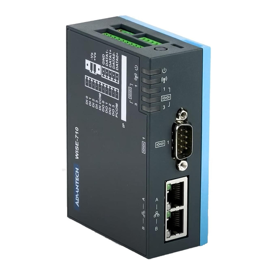
Introduction Figures 2.1 to 2.3 show the connector locations on the WISE-710-N600A gateway. Information about each connector and I/O slot is provided in the following sections. Figure 2.1 WISE-710-N600A Front Panel Figure 2.2 WISE-710-N600A Top View WISE-710-N600A User Manual... -
Page 15: Led Status Indicators
(Refer to Appendix A.3). LAN Connector (LAN1 ~ LAN2) WISE-710-N600A is equipped with a dual Gigabit LAN controller and Realtek RTL8364NBI Ethernet controller chip that is fully compliant with IEEE 802.3u 10/100/ 1000 BASE-T. The Ethernet port is a standard RJ-45 jack. LED indicators provided at the front show the device’s Link (green/orange) and Active (green LED) status (Refer... -
Page 16: Digital Input (Default Setting: Dry Contact)
ESD Protection: 4KV (contact), 8KV (air) Opto-Isolator Response: 50 μs 2.6.2 Digital Output Channels: 4 Output Voltage: 5 ~ 30 V Output Capability Sink: 24 mA max./channel Opto-Isolator Response: 50 μs WISE-710-N600A User Manual... -
Page 17: Micro Usb Slot
WISE-710-N600A is equipped with one micro USB slot. Micro SD Slot WISE-710-N600A is equipped with one micro SD slot that supports SD/MMC cards in Class 2, 4, 6, 8, 10. The supported capacity is up to 32 GB (SDHC). WISE-710-N600A User Manual... - Page 18 WISE-710-N600A User Manual...
-
Page 19: Chapter 3 Initial Setup
Chapter Initial Setup This chapter explains how to initialize WISE-710-N600A. Power Supply Din Rail Installation Wall Mount Installation Wi-Fi Module and Antenna Installa- tion Expansion Module Installation Software Installation... -
Page 20: Power Supply
Power Supply WISE-710-N600A is intended to be supplied by an approved power adapter or DC power source rated 24V , +-20%,0.5A, and TMA 55 °C. If you require more infor- mation, please contact Advantech. DIN Rail Installation Fasten the DIN rail bracket to the device using two screws... - Page 21 Install the DIN rail onto the DIN-rail bracket WISE-710-N600A User Manual...
-
Page 22: Wall Mount Installation
Wall Mount Installation Fasten the wall mount bracket to the device using four screws. Install the two mount latches. WISE-710-N600A User Manual... -
Page 23: Wi-Fi Module And Antenna Installation
Wi-Fi Module and Antenna Installation Remove the terminal plug. Open the rear cover of the device by pushing the clips on both sides using a flat- head screwdriver. WISE-710-N600A User Manual... - Page 24 Loosen and remove the grounding screw. Loosen and remove the two COM port nuts. Loosen and remove the two screws on the main board. WISE-710-N600A User Manual...
- Page 25 To remove the printed circuit board, first lift the board slightly. Then with the board tilted at a slight angle, carefully remove it from the device. Remove the side cover SMA dummy door. WISE-710-N600A User Manual...
- Page 26 Fasten the SMA cable in place using a socket wrench. The SMA cable should be routed as shown below. WISE-710-N600A User Manual...
- Page 27 Install the printed circuit board. Fasten the PCBA in place using two screws. WISE-710-N600A User Manual...
- Page 28 Replace and tighten the two COM port nuts. Replace and tighten the grounding screw. Insert the Wi-Fi module and fasten in place using one screw. WISE-710-N600A User Manual...
- Page 29 Plug the SMA cable into the wireless module. Replace the rear cover of the device. Install the antenna. WISE-710-N600A User Manual...
-
Page 30: Expansion Module Installation
Expansion Module Installation Open the rear cover of the device by pushing the clips on both side using a flat- head screwdriver. WISE-710-N600A User Manual... - Page 31 Attach the expansion module to the main terminal. Replace the rear cover. WISE-710-N600A User Manual...
-
Page 32: Software Installation
The putty tool can be used to connect to the WISE-710 gateway by following the steps outlined below. Step 1: Check the debug COM port connected Desktop->my computer->property->HYPERLINK "D:/[Tools]YouDaoDict/Dict/8.3.1.0/ resultui/html/index.html" \l "/javascript:;" device?HYPERLINK "D:/[Tools]YouDaoDict/ Dict/8.3.1.0/resultui/html/index.html" \l "/javascript:;" manager->COM&LPT Step 2: Configure the putty tool WISE-710-N600A User Manual... - Page 33 Step 3: Power on the WISE-710 device and log in (use root login) Step 4: Use the “ifconfig” command to check the IP address WISE-710-N600A User Manual...
-
Page 34: How To Use A Lan Port
LAN: CAT5.e + 100M/1000M external network Test flow Step 1: Login with the debug console Step 2: Enter test directory Step 3: Obtain the current ethernet IP Step 4: Run a full-load test script, wait 2 min (initializing 4G and other devices) WISE-710-N600A User Manual... - Page 35 Step 5: Open the remote desktop (use VNC Viewer 6.18.625) WISE-710-N600A User Manual...
-
Page 36: System Recovery Sop
Copy the “WISE-710-rx.yyyymmdd.tar.gz” package to your Linux desktop. Open “Terminal” on Ubuntu 16.04 LTS. user@ubuntu:/home/user# sudo su (Change to "root" authority) Input your password. root@ubuntu:/home/user# cd Desktop/ root@ubuntu:/home/user# tar zxvf WISE-710-rx.yyyymmdd.tar.gz Insert one SD card to the computer Check the SD card location (/dev/sdx) WISE-710-N600A User Manual... - Page 37 Copy the “WISE-710-rx-ubuntu.yyyymmdd.tar.gz” package to your Linux desktop. Open “Terminal” on Ubuntu 16.04 LTS. user@ubuntu:/home/user# sudo su (Change to "root" authority) Input your password root@ubuntu:/home/user# cd Desktop/ root@ubuntu:/home/user# zxvf WISE-710-rx-ubuntu.yyyym- mdd.tar.gz Insert one SD card into the computer Check the SD card location (/dev/sdx) WISE-710-N600A User Manual...
- Page 38 Boot from eMMC Boot the WISE-710 device from eMMC (SW2 1ON 2OFF). Click any key in boot delay, then recover all boot env values. Boot> env default -a Boot> saveenv Then disconnect and reconnect the power supply. WISE-710-N600A User Manual...
-
Page 39: Appendix A System Settings/Pin Assignments
Appendix System Settings/Pin Assignments... -
Page 40: Power Connector
In MDI configuration, MDI[0]+/- corresponds to BI_DA+/- and in MDI-X configuration, MDI[0]+/- corresponds to BI_DB+/-. MDI0- 10BASE-T and 100BASE-TX: In MDI configuration, MDI[0]+/- is used for the transmit pair and in MDIX configuration, MDI[0]+/- is used for the receive pair. WISE-710-N600A User Manual... -
Page 41: Com Ports
BI_DC+/- and MDI[3]+/- corresponds to BI_DD+/-. MDI3- 100BASE-TX: Unused 10BASE-T: Unused Left LED Right LED 10Link 100Link 1000Link Active Orange Green Green COM Ports A.3.1 COM1 1654000056 D-SUB connector 9P 90D(M) DIP 070241MR009S200ZU RS232 RS485 Console WISE-710-N600A User Manual... -
Page 42: Com2 And Com3
1654011848-02 micro USB 5P/0.65 mm/(F)/PA6T/RA/GFL/S/BK/B type Signal Description USB VBUS USB power output, USB 2.0 5 V/0.5A USB_P- USB 2.0 data - USB_P+ USB 2.0 data + Host: connected to the signal ground Device: not connected Ground for power return WISE-710-N600A User Manual... -
Page 43: Micro Sd Connector
Figure A.1 Connector and Switch Locations on the Main Board (Top/Rear) Label Function PCI Express mini card socket SW11 COM2 mode setting COM1 mode setting SW12 Termination resistor select Wet/Dry contact select Expansion connector RTC battery connector Boot mode select WISE-710-N600A User Manual... -
Page 44: Board (Top/Front)
Figure A.2 Connector and Switch Locations on the Main Board (Top/Front) Label Function Power in connector COM2, COM3 connector COM1 connector CN10 RJ45 connector Micro SD connector Micro USB connector Figure A.3 Connector and Switch Locations on the Daughter Board (Top/Front) Label Function CN11 Digital input/output connector WISE-710-N600A User Manual... -
Page 45: Mini Pcie Slot (Minipcie)
PCI Express dif- PETp0 ferential trans- mit pair SMB_DATA SMBus data PETn0 signal compli- ant with SMBus SMB_CLK 2.0 specifica- tions +1.5V PCI Express dif- PERp0 ferential receive pair +3.3Vaux PERn0 Functional reset PERST# to the card WISE-710-N600A User Manual... - Page 46 * +3.3 V aux is suspend power, power out to device = +3.3 V/1.1A * +3.3 V is core power * +1.5 V is core power, power out to device = +1.5 V/0.5A WISE-710-N600A User Manual...
-
Page 47: Com1 Rs232/485/Console Mode Setting (Sw9)
COM1 RS485/485/CAN Mode Setting Description This switch is used to select COM2 RS485/CAN mode settings Default RS485 mode Bit 1, 3 ON RS485 Mode Bit 2, 4 OFF Bit 2, 4 ON CAN Mode Bit 1, 3 OFF WISE-710-N600A User Manual... -
Page 48: Termination Resistor Selection (Sw12)
DI Wet/Dry Contact Selection (SW8) DI Wet/Dry Contact Selection Description This switch is used to select between wet or dry contact Default Dry contact Bit 2 ON Wet Contact Bit 1 OFF Bit 1 ON Dry Contact Bit 2 OFF WISE-710-N600A User Manual... -
Page 49: Boot Mode Selection (Sw2)
Boot Mode Selection (SW2) Boot Mode Selection Description This switch is used to select boot mode setting Default eMMC boot Bit 2 ON Boot from SD Bit 1 OFF Boot from Bit 1 ON eMMC Bit 2 OFF WISE-710-N600A User Manual... - Page 50 WISE-710-N600A User Manual...
- Page 51 WISE-710-N600A User Manual...
- Page 52 No part of this publication may be reproduced in any form or by any means, such as electronically, by photocopying, recording, or otherwise, without prior written permission from the publisher. All brand and product names are trademarks or registered trademarks of their respective companies. © Advantech Co., Ltd. 2019...
Need help?
Do you have a question about the WISE-710-N600A and is the answer not in the manual?
Questions and answers