
Subscribe to Our Youtube Channel
Related Manuals for Leuze electronic MSI 400


Summary of Contents for Leuze electronic MSI 400
- Page 1 MSI 400 Hardware T r a n s l a t i o n o f t h e o r i g i n a l o p e r a t i n g i n s t r u c t i o n s...
- Page 2 © 2016 Leuze electronic GmbH & Co. KG In der Braike 1 D-73277 Owen / Germany Phone: +49 7021 573-0 Fax: +49 7021 573-199 http://www.leuze.com info@leuze.de Leuze electronic MSI 400...
-
Page 3: Table Of Contents
Internal circuits ........................ 29 3.8.4 Deactivating the test pulses at the outputs................ 30 3.8.5 Single-channel use of outputs ................... 30 MSI-EM-I8 input expansion module.................. 31 3.9.1 Description ........................ 31 3.9.2 Display elements and terminal assignment ............... 32 3.9.3 Internal circuits ........................ 33 Leuze electronic MSI 400... - Page 4 10.3.1 Device state and LED displays in the controller modules .......... 68 10.3.2 Device state and LED displays in the safe input/output modules........ 70 10.3.3 Device state and LED displays in the standard input/output modules ...... 71 10.4 Support .......................... 73 10.5 Expanded diagnostics...................... 73 Leuze electronic MSI 400...
- Page 5 Order data...................... 94 13.1 Hardware modules and accessories.................. 94 13.2 Modules for contact expansion ..................... 96 Appendix...................... 97 14.1 Declaration of Conformity ..................... 97 14.2 Checklist for manufacturers .................... 98 14.3 Complete list of error messages ................... 99 Leuze electronic MSI 400...
-
Page 6: About This Manual
MSI 400 ##safety control the corresponding MSI 400 modules. Function of this document There are three manuals for the MSI 400 system with clearly delineated areas of application as well as in- stallation instructions and brief instructions for each module. -
Page 7: Scope Of Validity And Applicable Documents
About this manual Scope of validity and applicable documents This manual is valid for all MSI 400 safety control modules that are operated in connection with MSI 4xx and MSI.designer controller modules. Tab. 1.1: Overview of the MSI 400 documentation Document... -
Page 8: Copyright And Right To Make Changes
Reproduction of this document or parts of this document is only permissible within the limits of the statutory provision of the Copyright Act. Any modification or abridgment of the document is prohibited without the express written agreement of Leuze electronic. Allen-Bradley, CompactBlock Guard I/O, CompactLogix, ControlFLASH, ControlLogix, DH+, FactoryTalk,... -
Page 9: Safety
• have suitable technical training and • have been trained by the machine operator in the operation and applicable safety guidelines and • have access to the MSI 400 operating instructions and have read said instructions and have duly noted these and •... -
Page 10: Proper Use
• If you wish to use the MSI 400 system for domestic purposes, you need to take additional steps to pre- vent the emission of radio frequency interference in limit class B according to EN 55011. Here are some steps you might take: •... -
Page 11: General Safety Information And Protective Measures
• This manual must be provided to the operator of the machine on which the MSI 400 safety control is being used. The machine operator must be trained by qualified persons and is required to read this manual. -
Page 12: Environmentally Friendly Behavior
Safety Environmentally friendly behavior The modular MSI 400 safety control and the corresponding modules are designed such that they stress the environment as little as possible. They use only a minimum of power and resources. Ä Make sure that you also carry out work while always considering the environment. -
Page 13: Product Description
Product description Product description This section will provide you with information on the properties of the MSI 400 system and describes the setup and function. System properties Fig. 3.1: Modular MSI 400 safety control The MSI 400 system is characterized by the following system properties: •... -
Page 14: System Setup
MSI 400 system. Further information: Software manual, chapter "Special case: Expansion module MSI-XX" Examples Fig. 3.1: Example of a minimum MSI 400 system setup with a MSI 420/430 controller module Fig. 3.2: Example 2 - Maximum setup of a MSI 400 system Leuze electronic... -
Page 15: Version, Compatibility, And Features
4 inputs or 4 outputs can be configured as an option Version, compatibility, and features There are various module versions and function packages for the MSI 400 product family that enable vari- ous functions. This section will give you an overview as to which module version, which function package, and/or which version of the MSI.designer you will need to be able to use a certain function or a certain... -
Page 16: Controller Module Msi 410
24 V supply voltage for all modules, except for supply of outputs GND of supply voltage I1 - I20 Safe, digital inputs Q1 - Q4 Safe, digital outputs 24 V supply voltage of outputs Q1 - Q4 T1 - T4 Test signal outputs Leuze electronic MSI 400... - Page 17 The controller module has a mini-USB interface with the following functions: • Transfer of the configuration from MSI.designer to the program removable storage • Reading of configuration from program removable storage in MSI.designer • Diagnostics of the MSI 400 system with MSI.designer Tab. 3.5: USB interface pin assignment...
-
Page 18: Internal Circuits
< 4 ms, the test periods ≥ 200 ms. Short-circuits past 24 V DC (after High) at in- puts that are connected to test outputs are detected independently of the length of the test gaps. Make note of this during wiring (e.g. through separate routing or protected lines)! Leuze electronic MSI 400... -
Page 19: Deactivating The Test Pulses At The Outputs
Ä Restart the MSI 400 system by switching off the supply voltage. You will thus deactivate the test pulses at an output of a MSI 400 module: Ä Connect an output element to the MSI 4xx module. -
Page 20: Controller Module Msi 420
IQ1 to IQ4 Tab. 3.7: MSI 420/430 pin assignment assignment 24 V supply voltage for all modules, except for supply of outputs GND of supply voltage I1 - I16 Safe, digital inputs Q1 - Q4 Safe, digital outputs Leuze electronic MSI 400... - Page 21 • Transfer of the configuration from MSI.designer to the program removable storage • Reading of configuration from program removable storage in MSI.designer • Diagnostics of the MSI 400 system with MSI.designer • Continuous diagnostics of the MSI 400 system via a connected PLC Tab. 3.9: RJ 45 bushing pin assignment...
-
Page 22: Internal Circuits
< 4 ms, the test periods ≥ 200 ms. Short-circuits past 24 V DC (after High) at in- puts that are connected to test outputs are detected independently of the length of the test gaps. Make note of this during wiring (e.g. through separate routing or protected lines)! Leuze electronic MSI 400... -
Page 23: Deactivating The Test Pulses At The Outputs
Ä Switch off all of the safety outputs without test pulses simultaneously for at least one second via the logic program of the controller module. Ä Restart the MSI 400 system by switching off the supply voltage. You will thus deactivate the test pulses at an output of a MSI 420/430 module: Ä... -
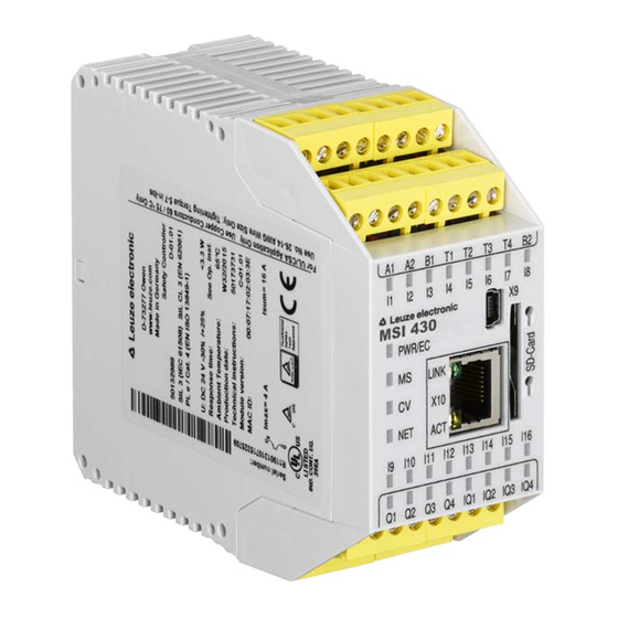
Page 24: Controller Module Msi 430
The displays of the MS and CV LEDs as well as the terminal assignment of the USB and Ethernet interface are identical to those of the MSI 420 controller module. Further information: Display elements, interfaces, and terminal description [chapter 3.5.2] Leuze electronic MSI 400... -
Page 25: Msi-Sd-Card Removable Storage
Description The system configuration of the entire MSI 400 system is stored in the MSI-SD-CARD program removable storage. This has the advantage that the MSI 400 system does not have to be reconfigured when modules are replaced. The MSI-SD-CARD removable storage is an SD card that is produced and formatted specially for use in the controller modules. - Page 26 127.0.0.1 ethernet:mask: IPv4 network mask 255.0.0.0 to 255.255.255.253 ethernet:gw: IPv4 gateway 0.0.0.0 or 0.0.0.1 to 223.255.255.254 and not 127.0.0.1 ethernet:multicast: IPv4 Multicast membership for the 224.0.0.0 device search by MSI.designer 0.0.0.0 usb:vcom: USB interface activation Leuze electronic MSI 400...
-
Page 27: Msi-Em-Io84 Input/Output Expansion Module
Ä The LEDs of inputs I1 to I8 indicate the state of the inputs at an update interval of about 64 3.8.2 Display elements and terminal assignment MS LED 8 input LEDs 4 output LEDs Fig. 3.9: Display elements of the MSI-EM-IO84 module Leuze electronic MSI 400... - Page 28 Further information: Device state and LED displays in the safe input/output modules [chapter 10.3.2] Terminal assignment Tab. 3.12: MSI-EM-IO84 terminal assignment reference Terminal assignment X1/X2 Test output 1 / test output 2 I1–I4 Inputs 1 to 4 24 V I5–I8 Inputs 5 to 8 Q1–Q4 Outputs 1 to 4 Leuze electronic MSI 400...
-
Page 29: Internal Circuits
Product description 3.8.3 Internal circuits Fig. 3.10: Internal circuits of the MSI-EM-IO84 module: Safe inputs and test outputs Fig. 3.11: Internal circuits of the MSI-EM-IO84 module: Safety outputs Leuze electronic MSI 400... -
Page 30: Deactivating The Test Pulses At The Outputs
Ä Switch off all of the safety outputs without test pulses simultaneously for at least one second via the logic program of the controller module. Ä Restart the MSI 400 system by switching off the supply voltage. You will thus deactivate the test pulses at an output of a MSI-EM-IO84 module: Ä... -
Page 31: Msi-Em-I8 Input Expansion Module
(X1, X3, X5, and X7) cannot be detec- ted. The same applies accordingly to the even-numbered test outputs X2, X4, X6, and X8. Make note of this during wiring (e.g. through separate routing or protected lines)! Leuze electronic MSI 400... -
Page 32: Display Elements And Terminal Assignment
Tab. 3.13: Terminal assignment reference of the MSI-EM-I8 module Terminal assignment X1/X3 Test signal 1 X2/X4 Test signal 2 I1 – I4 Inputs 1 to 4 I5 – I8 Inputs 5 to 8 X5/X7 Test signal 1 X6/X8 Test signal 2 Leuze electronic MSI 400... -
Page 33: Internal Circuits
Product description 3.9.3 Internal circuits Fig. 3.13: Internal circuits of the MSI-EM-I8 module: Safety inputs and test outputs Leuze electronic MSI 400... -
Page 34: Msi-Em-Io84Np Input/Output Expansion Module
4 ms. Restricted selection of inputs Only the single-channel inputs are available to be selected in the configuration for the MSI-EM-IO84NP ex- pansion module, for example: Fig. 3.14: single-channel inputs for the MSI-EM-IO84NP expansion module Leuze electronic MSI 400... -
Page 35: Display Elements And Terminal Assignment
Further information: Device state and LED displays in the standard input/output modules [chapter 10.3.3] Terminal assignment Tab. 3.14: MSI-EM-IO84NP terminal assignment reference Terminal assignment 24 V I1–I4 non-secure inputs 1 to 4 IY5–IY8 non-secure inputs/outputs combination 5 to 8 Y1–Y4 non-secure outputs 1 to 4 Leuze electronic MSI 400... -
Page 36: Internal Circuits
Product description 3.10.3 Internal circuits Fig. 3.16: Internal switching circuit of the MSI-EM-IO84NP module: non-secure inputs Fig. 3.17: Internal switching circuit of the MSI-EM-IO84NP module: non-secure outputs Leuze electronic MSI 400... - Page 37 Internal switching circuit of the MSI-EM-IO84NP module: non-secure inputs/outputs combination WARNING Use of the IY5–IY8 inputs/outputs When using the combination connections as input, the signal input voltage to IY5–IY8 may never be greater than the supply voltage to A1/A2. Leuze electronic MSI 400...
-
Page 38: Connecting Devices
This section describes the connection of safety sensors and actuators to the MSI 400 system and provides setup information for selected functions. The MSI 400 system supports applications up to Performance Level PL e (as per EN ISO 13849-1) and up to Safety Integrity Level SIL CL3 (as per EN 62061). - Page 39 After project planning, you will receive a report in the MSI.designer software with the following content (Ac- tivate: Tab bar | View Report): • Logic report • List of parts • Wiring information Tab. 4.1: Excerpt from exemplary documentation in the MSI.designer software Leuze electronic MSI 400...
-
Page 40: Safety Command Devices And Electromechanical Safety Switches
Max. number of emergency stop buttons switched in series: cascading note max. line resistance of 100 Ω Synchronous time 4 ms to 30 ms or deactivated NOTICE You can find additional information in the operating instructions for the ESB200 emergency stop button. Leuze electronic MSI 400... -
Page 41: Electromechanical Safety Switch Without Lock
Two-channel, Channel 1: Contact between Ub and without testing Channel 2: Contact between Ub and Inductor at Q3 Two-channel, Channel 1: Contact between T1 and with testing Channel 2: Contact between T2 and Inductor at Q1 Leuze electronic MSI 400... -
Page 42: Enable Switch
NO 2: between T2 and I8 Tab. 4.8: Functions Function Info Testing Possible Series connection Not possible Synchronous time 4 ms to 30 ms or deactivated NOTICE You can find additional information in the operating instructions for the respective devices. Leuze electronic MSI 400... -
Page 43: Two-Hand Control
Channel 2: Contact between test output T2 and I2 Short-circuit-forming Channel 1: Contact between multi-safety mat in 4- T1 and I1 conductor technology, Channel 2: Contact between at test output T2 and I2 Leuze electronic MSI 400... - Page 44 Test output 1 Test output 2 MSI-EM-IO84 (to B‑07) MSI-EM-IO84 (from B‑08) MSI 4xx (to D‑01.xx) MSI 4xx (from D‑03.xx) 200-1000 400-1000 800-1000 1000 1000 1000 1000 1000 1000 1000 Obtain the values from the report in MSI.designer. Leuze electronic MSI 400...
-
Page 45: Connection Of Multiple Safety Mats/Bumpers
In addition, there are elements for a start and stop button, reset button, and device monitoring (EDM). Tab. 4.13: Function of potential-free contacts Function Info Testing Possible Series connection Possible Discrepancy time Further information: Software manual Leuze electronic MSI 400... -
Page 46: Contactless Safety Sensors
Possible; note max. line resistance of 100 Ω and correct setting cascading of test pulse time Synchronous time Preset at 1500 ms NOTICE You can find additional information in the operating instructions for the magnetic safety switches. Leuze electronic MSI 400... -
Page 47: Inductive Safety Switches
With OSSD OSSD1 at I1 OSSD2 at I2 Tab. 4.20: Functions with transponders Function Info Series connection/ Possible, depending on type used cascading NOTICE You can find additional information in the operating instructions for the respective transponder switch. Leuze electronic MSI 400... -
Page 48: Testable Single-Beam Safety Light Barriers
ON delay of the cascade is 10 ms (otherwise, the test gap will lead to switch-off). Note the maximum line resistance of 100 Ω. NOTICE You can find additional information in the operating instructions for the type 2 single-beam safety light barriers. Leuze electronic MSI 400... -
Page 49: Testable Type 4 Single-Beam Safety Light Barriers
X8) to the test input of the transmitter and from the output of the receiver to the safe input of the module (I1 to I8). Otherwise, a short-circuit between the signals may prevent error de- tection by this test. Leuze electronic MSI 400... -
Page 50: Information On Installing Testable Single-Beam Safety Light Barriers
= minimum distance to reflective surface Fig. 4.2: Minimum distance "a" as a function of distance "D" for testable single-beam safety light barriers with 10° aperture angle NOTICE Diagrams of the safety light barriers can be found in the respective operating instructions. Leuze electronic MSI 400... - Page 51 Ä With reciprocal installation of the transmitter and receiver, ensure that the light beam of transmitter S1 cannot be received by receiver R3 and that the light beam of transmitter S3 cannot be received by receiver R1. Fig. 4.3: Installation so as to prevent optical interaction Leuze electronic MSI 400...
-
Page 52: Espe - Electro-Sensitive Protective Equipment
Ä Earth the shielding on both sides, i.e. on the sensor and on the module. Ä Position the screen earthing terminal as close to the module as possible and keep the stripped ends for connection to the module as short as possible. Leuze electronic MSI 400... -
Page 53: Safety Outputs
Ä Do not connect any loads that exceed the rated values of the safety outputs. Ä Wire the MSI 400 system such that no 24 V DC signals can unintentionally make contact with the safety outputs. -
Page 54: Special Functions
(BWS), e.g. a safety light curtain. For further information, observe the information in the software manual in the following chapter: Function blocks for 4-Sensor muting (time-controlled), 4-Sensor muting (sequential), and 2-Sensor muting (time-controlled, with/without direction detection) Leuze electronic MSI 400... -
Page 55: Installing/Removing
The mounting boxes are suitable for 35 mm hat rails as per EN 60715. • Sequence of modules: The MSI 400 system has the controller module on the far left. The two optional gateways follow directly to the right next to the controller module. The expansion modules only follow thereafter. - Page 56 Ä Make sure that the module is securely seated on the hat rail. Attempt to pull the module from the hat rail using slight pressure. If the module stays connected to the hat rail during this test, then the installation is correct. Leuze electronic MSI 400...
- Page 57 Ä If you are installing multiple modules: Push the individual modules together in the direction of the arrow until the lateral plug connection between the modules audibly latches into position. Leuze electronic MSI 400...
- Page 58 After installation Once you have installed the modules, the following steps are required: • Connect the modules electrically. [chapter 4] • Configure modules (see: software manual). • Check the installation before first commissioning. [chapter 9.2] Leuze electronic MSI 400...
-
Page 59: Removing Modules From The Hat Rail
Installing/removing Removing modules from the hat rail Step 1: Removing a controller module Ä Deenergize the MSI 400 system. Ä Remove plug-in terminals with wiring and remove the end terminal. End terminal Plug-in terminal End terminal Ä If expansion modules or gateways are used: Slide the controller module in the direction of the arrow until the lateral plug connection is disconnected. - Page 60 Installing/removing Step 2: Removing gateways and expansion modules Ä Deenergize the MSI 400 system. Ä Remove any plug-in terminals with wiring and remove the end terminals. End terminal End terminal Plug-in terminal Ä Pull the modules apart from one another individually in the direction of the arrow until the lateral plug connection is disconnected.
-
Page 61: Electrical Installation
This section describes the electrical installation of the MSI 400 system in the switchbox. You can find addi- tional information on the electrical connection of other devices to the MSI 400 system in the section on the respective device (see Product description [chapter 2.5.2]). - Page 62 • The power supply must meet the regulations for low-voltage with safe disconnection (SELV, PELV) in accordance with EN 60664 and EN 50178 (equipping high-voltage systems with electronic equipment). • You must connect all modules in the MSI 400 system, the connected safety equipment and the voltage supplies to the same 0-V DC connection (GND).
-
Page 63: Internal Wiring Of The Supply Voltage
Internal wiring of the supply voltage Test outputs Controller Gateway 1 Gateway 2 Expansion Expansion Expansion module module 1 module 2 module n Outputs Outputs Outputs Load Load Load Load Load Fig. 7.1: Internal wiring of the MSI 400 supply voltage Leuze electronic MSI 400... -
Page 64: Configuration
MSI.designer software. These devices have their own mechanisms for configuration and verification. • The system configuration of the entire MSI 400 system is stored in the program removable storage. This has the advantage that the system does not have to be reconfigured when modules and/or gate- ways are replaced. -
Page 65: Commissioning
Commissioning cannot take place without testing being conducted by a qualified person! Ä Before you place the system in which you use a MSI 400 safety control in operation for the first time, it must be tested and documented for release by a qualified person. -
Page 66: Diagnostics
10.2 Error statuses With certain error functions or a faulty configuration, the MSI 400 safety control will go into a safe state. The LEDs for the individual modules of the safety control will indicate the respective error level. There are various error levels depending on the type of error: Configuration error •... -
Page 67: Error Displays In The Status Leds, Error Messages, Troubleshooting Measures
This section contains the most important error codes, potential causes, and potential measures for eliminat- ing errors. These error codes and error messages can be displayed as well in the MSI.designer Dia- gnostics view if you have established a connection with the MSI 400 system. NOTICE Ä... -
Page 68: Device State And Led Displays In The Controller Modules
Green One or more inputs have a cable break or short-circuit to 24V. Red/green Or there is a sequence/synchronous time flashing error at a two-channel input. Or an output has a test error (e.g. short-cir- cuit). Leuze electronic MSI 400... - Page 69 Signal level at the input terminal is 24V. Green Output LED Meaning Additional info Output has a test error. Applies to Q1..Q4 and IQ1..IQ4 Green flash- ing (1 Hz) Output is switched off. Output is switched off. Green Leuze electronic MSI 400...
-
Page 70: Device State And Led Displays In The Safe Input/Output Modules
All outputs are switched off. this has been done multiple times, then re- place module in which the red LED is flash- ing (2 Hz). In order to contain the module affected, use the diagnostics display in MSI.de- signer. Leuze electronic MSI 400... -
Page 71: Device State And Led Displays In The Standard Input/Output Modules
16.8V to 30V. Green flash- ing (1 Hz) System in the run state and the voltage supply to A1 is within the range of 16.8V to Green 30V. Invalid configuration Red flashing (1 Hz) Leuze electronic MSI 400... - Page 72 Displays of output LEDs Output LEDs (Y1-Y4 and IY5-IY8) Meaning Output is switched off. Output is switched off. Green Output has an error. (e.g. output driver overloaded) Green (1 Hz) synchronous with the red MS LED Leuze electronic MSI 400...
-
Page 73: Support
Please see the following for more detailed information: • Software manual • A complete list of all error messages is contained in the Appendix [chapter 14.3]. Leuze electronic MSI 400... -
Page 74: Maintenance
The following section provides information on regular tests and the replacement of MSI 400 modules. Do not attempt to remove, repair, or modify the MSI 400 modules. This may lead to loss of safety functions. Furthermore, this will void any warranty claim you may have against Leuze electronic GmbH. -
Page 75: Replacing Devices
11.2 Replacing devices A critical error in one of the MSI 400 modules will affect the entire network. Therefore, devices that have critical errors must be quickly repaired or replaced. We recommend keeping replacement MSI 400 module devices at the ready so that you can reestablish network operation as quickly as possible. -
Page 76: Technical Data
In particular, for existing projects with sensor elements for safety mats and bumpers, this exten- sion of the response times must be adhered to (e.g. in the case of replacement of a MSI 4xx module). Leuze electronic MSI 400... - Page 77 0.0 ms MSI.designer If function blocks with switch-off delay are used in the logic plan, then these times have to be added to the response time. Actuator response time + 35.0 ms Manufacturer informa- tion Total time 80.6 ms Leuze electronic MSI 400...
-
Page 78: Minimum Switch-Off Time
Data from gateways or the non-secure MSI-EM-IO84NP I/O expansion module are categorically not se- cure. Default values are taken up in the error state of the controller. The default value of IO data is 0 and the default value of state data is 1. Leuze electronic MSI 400... -
Page 79: Safety Technology Reference Values
Technical data 12.2 Safety technology reference values 12.2.1 Controller modules without I/O expansion Tab. 12.5: Safety technology reference values for MSI 400 (without I/O expansion) Characteristic values Configuration of safety outputs Safety In- Category Perform- PFHd tegrity (EN ISO ance level Output groups:... -
Page 80: Controller Modules With Safe I/O Expansions
Technical data 12.2.2 Controller modules with safe I/O expansions Tab. 12.6: Safety technology reference values for MSI 400 (with I/O expansion) Characteristic values Configuration of safety outputs Safety In- Category Perform- PFHd tegrity (EN ISO ance level Output groups: Level 13849-1) (EN ISO MSI 4xx: (IEC 61508) -
Page 81: Data Sheet
Dimensions (W × H × L) 45 × 96.6 × 121 mm 45 × 107 × 121 mm Weight 290 g (± 5%) 290 g (± 5%) Power supply for the system (A1, A2) Supply voltage 24 V DC (16.8 to 30 V DC) Leuze electronic MSI 400... - Page 82 Total of all test outputs: max. 120 mA Test pulse rate (test period) 1 to 25 Hz, configurable Test pulse duration (test gap) 1 to 100 ms, configurable Load capacity 1 µF for test gap ≥ 4 ms 0.22 µF for test gap 1 ms Leuze electronic MSI 400...
- Page 83 When safety outputs are being used without test pulses, then either all of the safety outputs without test pulses must be switched off at least once a year simultaneously for at least one second or the MSI 400 system must be restarted by switching off the supply voltage.
-
Page 84: Safe Input/Output Expansion Module
Power consumption Switch-on time Max. 18 s Short-circuit protective device 4 A gG (with tripping characteristic B or C) Input circuit (I1–I8) Input voltage HIGH 13 to 30 V DC Input voltage LOW -5 to +5 V DC Leuze electronic MSI 400... - Page 85 Thus, a maximum of eight testable sensor cas- cades are possible per module with a maximum of 30 mA each. The total current of the MSI 400 system is limited to a maximum of 1.28 A. This corresponds, for example, to a maximum of 32 testable sensor cascades with 30 mA each plus 64 tactile...
- Page 86 When safety outputs are being used without test pulses, then either all of the safety outputs without test pulses must be switched off at least once a year simultaneously for at least one second or the MSI 400 system must be restarted by switching off the supply voltage.
-
Page 87: Safe Input Expansion Module
139 g (± 5%) Input circuit (I1 to I8) Input voltage HIGH 13 to 30 V DC Input voltage LOW -5 to +5 V DC Input current HIGH 2.4 to 3.8 mA Input current LOW -2.5 to 2.1 mA Leuze electronic MSI 400... - Page 88 Thus, a maximum of eight testable sensor cas- cades are possible per module with a maximum of 30 mA each. The total current of the MSI 400 system is limited to a maximum of 1.28 A. This corresponds, for example, to 32 inputs of testable sensors with 30 mA and 64 inputs of MSI-EM-IO84 or MSI-...
-
Page 89: Standard Input/Output Expansion Module
4 to max. 8 (depending on configuration) Input voltage HIGH 13 V DC… 30 V DC Input voltage LOW –3 V DC … +5 V DC Input current HIGH 2 mA … 3.5 mA Input current LOW 0 mA… 1.0 mA Leuze electronic MSI 400... - Page 90 TU ≤ 45°C Max. 4.0 A TU ≤ 55 °C Max. 3.2 A TU ≤ 65°C Max. 2.5 A Response time Depending on logic setup (Details: System response times [chapter 12.1]) Data interface Internal safety bus Leuze electronic MSI 400...
-
Page 91: Dimensional Drawings
Technical data 12.4 Dimensional drawings 12.4.1 Controller module Screw terminal Leuze electronic MSI 400... - Page 92 Technical data Spring-loaded terminal Leuze electronic MSI 400...
-
Page 93: Input/Output Expansion Modules
Technical data 12.4.2 Input/output expansion modules MSI-FB-CANOPEN MSI-FB-PROFIBUS Fig. 12.24: Dimensions of the input/output expansion modules (mm) Leuze electronic MSI 400... -
Page 94: Order Data
Order data Order data 13.1 Hardware modules and accessories Tab. 13.1: Order numbers for the MSI 400 modules Type Description Part number MSI 410-01 Controller module, USB connection, 50132984 20 inputs / 4 outputs Screw terminals, pluggable MSI 410-03 Controller module, USB connection,... - Page 95 4 inputs / 4 outputs and 4 configurable inputs or out- puts Screw terminals, pluggable MSI-EM-IO84NP-03 Standard input/output expansion 50132998 4 inputs / 4 outputs and 4 configurable inputs or out- puts Screw-loaded terminals, pluggable MSI-FB-ETHERCAT EtherCAT Gateway 50132999 Leuze electronic MSI 400...
-
Page 96: Modules For Contact Expansion
2 x 2 NC (normally closed contact), 2 x 1 NO (nor- mally open contact), Screw terminals, pluggable MSI-SR-CM42R-03 Contact expansion with 2 relay groups, 24 V DC, 50133015 2 x 2 NC (normally closed contact), 2 x 1 NO (nor- mally open contact), Spring-loaded terminals, pluggable Leuze electronic MSI 400... -
Page 97: Appendix
Appendix Appendix 14.1 Declaration of Conformity Leuze electronic MSI 400... -
Page 98: Checklist For Manufacturers
• Functional check of the command devices, sensors, and actuators connec- ted to the safety control • Test of all switch-off paths Have you ensured that a complete test of the safety functions has been carried out after every configuration change to the safety control? Leuze electronic MSI 400... -
Page 99: Complete List Of Error Messages
The Ethernet or USB connection was interrupted. 1010000E Error Unexpected message received. Separate connec- Support request tion 1010000F Error The message from the controller is Separate connec- Support request corrupt. tion Leuze electronic MSI 400... - Page 100 10300002 Error The data of the logic analyzer Repeat could not be loaded. support request 10300003 Error Input/output was not found. Support request 10400001 Error The log messages could not be Check Windows saved. user rights Leuze electronic MSI 400...
- Page 101 10700009 Error Failed to import library, since cor- responding elements already exist. 1070000A Error File cannot be loaded, incorrect Search for a new signature. program version: Main menu > via > Update, or support request Leuze electronic MSI 400...
- Page 102 Error An element is not allowed for groupings. 14000007 Error Function blocks are not compatible If you use this con- with the selected controller mod- troller module, the ule. corresponding func- tion blocks will be deleted. Leuze electronic MSI 400...
- Page 103 Warning Pulse length must be 4..100ms in Configuration re- Change system increments of 4ms quired configuration and reload 22010240 Warning Maximum count of function blocks Configuration re- Change system or mapping exceeded quired configuration and reload Leuze electronic MSI 400...
- Page 104 Processing error at I5/I6 System continues to run 23010007 Warning Processing error at I7/I8 System continues to run 23010009 Warning Processing error at I9/I10 System continues to run 2301000B Warning Processing error at I11/I12 System continues to run Leuze electronic MSI 400...
- Page 105 240A0004 Warning Output error at IQ1 System continues Check outputs to run; affected out- puts switch off 240A0005 Warning Output error at IQ2 System continues Check outputs to run; affected out- puts switch off Leuze electronic MSI 400...
- Page 106 Restart forcing to run 2413xxxx Warning Problem with forcing System continues Restart forcing to run 2414xxxx Warning Problem with forcing System continues Restart forcing to run 2415xxxx Warning Problem with forcing System continues Restart forcing to run Leuze electronic MSI 400...
- Page 107 Test pulse error at I8 System continues Check cabling to run 241D0009 Warning Test pulse error at I9 System continues Check cabling to run 241D000A Warning Test pulse error at I10 System continues Check cabling to run Leuze electronic MSI 400...
- Page 108 2435FF06 Warning Safety mat cable break System continues Check cabling to run 2435FF08 Warning Safety mat cable break System continues Check cabling to run 2435FF0A Warning Safety mat cable break System continues Check cabling to run Leuze electronic MSI 400...
- Page 109 Stuck-at-high safety mat at I10 System continues Check cabling to run 243CFx0A Warning Stuck-at-high safety mat at I11 System continues Check cabling to run 243CFx0B Warning Stuck-at-high safety mat at I12 System continues Check cabling to run Leuze electronic MSI 400...
- Page 110 Warning Supply voltage too high System continues Supply voltage to run must be set cor- rectly 2503xxx1 Error Supply voltage A1 too low System stop; Supply voltage voltage OFF-ON re- must be set cor- quired rectly Leuze electronic MSI 400...
- Page 111 Ethernet connection too slow System continues to run 2B0Exxxx Warning Time for logic processing ex- System continues ceeded to run 2Bxxxxxx Warning Internal error System continues to run 3409xxxx Warning Invalid force request System continues to run Leuze electronic MSI 400...
- Page 112 Safety mat cable break System continues to run 3702xxxx Warning Short circuit, stuck-at-low, VCC or System continues GND break to run 37040003 Warning Cross-reference at Q1/Q2 System continues to run 3704000C Warning Cross-reference at Q3/Q4 System continues to run Leuze electronic MSI 400...
- Page 113 Error in system configuration System continues to run 390Axxxx Warning Error in system configuration System continues to run 390Bxxxx Warning Error in system configuration System continues to run 390Cxxxx Warning Error in system configuration System continues to run Leuze electronic MSI 400...
- Page 114 Warning CAN controller TEC > 255 System continues to run 4505xxxx Warning Transmission of a message was System continues faulty to run 4506xxxx Warning Data loss in transmit buffer due to System continues overload to run Leuze electronic MSI 400...
- Page 115 52xxxxxx Warning Ethernet/IP error System continues to run 60000000 Info Log file deleted System continues to run 60000001 Info Base module firmware System continues to run 60000002 Info Base module serial number System continues to run Leuze electronic MSI 400...
- Page 116 System continues to run 6Axxxxxx Warning Communication error (Ethernet/ System continues USB) to run 6B03xxxx Warning Project file faulty Configuration re- quired 6B04xxxx Warning Project file faulty Configuration re- quired 6Bxxxxxx Warning File error Configuration re- quired Leuze electronic MSI 400...
Need help?
Do you have a question about the MSI 400 and is the answer not in the manual?
Questions and answers