
Related Manuals for Leuze electronic ODS 9


Summary of Contents for Leuze electronic ODS 9
- Page 1 ODS 9 Laser distance sensor O r i g i n a l o p e r a t i n g i n s t r u c t i o n s...
- Page 2 © 2018 Leuze electronic GmbH & Co. KG In der Braike 1 D-73277 Owen / Germany Phone: +49 7021 573-0 Fax: +49 7021 573-199 http://www.leuze.com info@leuze.com Leuze electronic ODS 9...
-
Page 3: Table Of Contents
Teach-in / teach......................... 39 7.1.4 Teaching the output functions via the multifunction input.......... 39 7.1.5 Teaching the output functions via the IO-Link system commands ........ 41 Setting measurement value processing and filtering ............ 43 Reset to factory settings ....................... 43 Leuze electronic ODS 9... - Page 4 Order guide and accessories................ 69 13.1 Type overview ODS 9 ...................... 69 13.2 Accessories – cables and connectors .................. 69 13.3 Other accessories ......................... 71 13.3.1 Accessories – PC connection.................... 71 13.3.2 Accessories – IO-Link master ................... 71 EC Declaration of Conformity................ 72 Leuze electronic ODS 9...
-
Page 5: About This Document
Software frame for management of device managers (DTM) Functional earth IODD IO Device Description File with information on process data and device parameters Max. Maximum Min. Minimum National Electric Code Optical Distance Sensor Optical distance sensor OLED Organic Light Emitting Diode Organic LED Leuze electronic ODS 9... -
Page 6: Important Terms
IO-Link data storage DSUpload Data Storage Upload. Upload to the data memory of the connected IO-Link master. Accuracy Maximum expected deviation of the measurement value between the de- termined and real distance value within the specified measurement range. Leuze electronic ODS 9... - Page 7 Triangulation measurement Distance measuring procedure, which determines the distance of an object principle by the incidence angle of the light reflected from the object. Leuze electronic ODS 9...
-
Page 8: Safety
Ä The device must not be opened. There are no user-serviceable parts inside. Ä Repairs must only be performed by Leuze electronic GmbH + Co. KG. Leuze electronic ODS 9... -
Page 9: Competent Persons
Ä The device must not be tampered with and must not be changed in any way. There are no user-serviceable parts inside the device. Ä Repairs must only be performed by Leuze electronic GmbH + Co. KG. Leuze electronic ODS 9... -
Page 10: Device Description
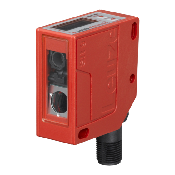
PC and the measurement values visualized. Stored parameter sets can be duplicated in other sensors. The connection is made via the IO-Link USB master, which is available as an accessory. Device housing Status LEDs Control buttons Display Transmitter Receiver Connection Fig. 3.1: Device construction Leuze electronic ODS 9... -
Page 11: Operating Principle
Special accessories are available for the laser distance sensor (see chapter 13 "Order guide and acces- sories"): • Mounting systems for mounting on rods • Connection cables • IO-Link USB master set for connecting to a PC • IO-Link master for cascading or integrating in a higher-level network Leuze electronic ODS 9... -
Page 12: Connection Technology
– Enter button: select function, confirm/enter value The and buttons have different functions depending on the operating situation. These functions are displayed via icons at the right edge of the display (see chapter 3.3.4 "Meaning of the display icons"). Leuze electronic ODS 9... - Page 13 (see chapter 3.4.6 "Settings menu"). The password is permanently set to 165. In ad- dition, a complete button lock can be activated using the lock function (device access locks, bit 2) (see the table "Status displays on the display"). Leuze electronic ODS 9...
- Page 14 The measurement value has an offset and/or the gradient is falling (-1) Lock function: Button lock activated via IO-Link (device access locks, bit 3) The button lock can also be enabled and set using the configu- ration software Sensor Studio: Configuration > Local operation Leuze electronic ODS 9...
-
Page 15: Meaning Of The Display Icons
Activate the desired selection with the enter button NOTICE The number of bars at the left edge of the display indicates the current menu level. For information on the meaning of the display icons, see chapter 3.3.4 "Meaning of the display icons". Leuze electronic ODS 9... -
Page 16: Input Menu
Hysteresis ODS9L1.8…: 10 mm SSC1_Logic Behavior of the switching output if an High active object is within the taught/configured switching distance. • High active: switching output ac- tive (high) • Low active: switching output in- active (low) Leuze electronic ODS 9... - Page 17 Hysteresis ODS9L1.8…: 10 mm SSC2_Logic Behavior of the switching output if an High active object is within the taught/configured switching distance. • High active: switching output ac- tive (high) • Low active: switching output in- active (low) Leuze electronic ODS 9...
-
Page 18: Analog Output Menu
It is also possible to invert the working range of the analog output, i.e., the lower limit of the measurement range is set to a larger value than the upper limit. This creates a descending characteristic output curve. Leuze electronic ODS 9... -
Page 19: Application Menu
Medium Averages approx. 50 % of the central mea- surement values Strong Averages approx. 25 % of the central mea- surement values Distance correction Distance calibration Offset Gradient Ascending Falling Preset position Preset calculation Inactive Execute Leuze electronic ODS 9... - Page 20 Due to physical reasons, the measurement results are not all the same. The measurement values have a scatter which corresponds to a normal distribution comprising a large number of similar measurement val- ues and a small number of excessively high or low measurement values (outliers, spikes). Leuze electronic ODS 9...
- Page 21 • Falling on one side: 12 % • Used center area, averaged: 76 % Fig. 3.3: Coarse filter depth • Medium • Falling on one side: 24 % • Used center area, averaged: 52 % Fig. 3.4: Medium filter depth Leuze electronic ODS 9...
- Page 22 Negative measurement values may occur if an offset is set. The offset/preset calculation is available as a teach function. The assignment of the teach time frame can be read out via IO-Link (see chapter 7 "Starting up the device"). Leuze electronic ODS 9...
- Page 23 Distance correction > Preset calculation > Execute An offset of +50 mm is automatically calculated and stored in the configuration. • Object distance: 300 mm Output to display and interface: 350 mm • Object distance: 400 mm Output to display and interface: 450 mm Leuze electronic ODS 9...
-
Page 24: Settings Menu
The DSUpload flag is set. The "Data Storage" (DS) parameter memory is updated. Only local The change is only temporary or local on the device or no changes data memory is used. (only local The DSUpload flag is cleared. changes) Leuze electronic ODS 9... -
Page 25: Ending Configuration
Ä In process mode, press a control button to activate the menu display. Input Output SSC1 Ä Press the navigation button ð The display shows "Output SSC1" in the upper menu line. Output SSC1 Output Ä Press the enter button to select Output SSC1. SSC1 SP1 (dist.) 00250 mm Leuze electronic ODS 9... - Page 26 The newly set value "00100 mm", which is stored in non-volatile memory, appears in the display. SSC1 SP2 (near) 00100 mm Ä Press the navigation button repeatedly until the ← icon appears in the upper menu line. ← SSC1 SP1 (dist.) Leuze electronic ODS 9...
- Page 27 IO-Link master. Ä Press and hold down the enter button for at least 5 s – until the "Exit menu" message appears on the display. Ä Confirm with the enter button Leuze electronic ODS 9...
-
Page 28: Applications
The laser distance sensor is designed for the following areas of application: • Distance measurement • Thickness measurement • Positioning • Diameter determination • Fill level indicator Wood width measurement Fig. 4.1: Application example: wood width measurement Leuze electronic ODS 9... -
Page 29: Assembly Inspection
Applications Assembly inspection Fig. 4.2: Application example: assembly inspection Leuze electronic ODS 9... -
Page 30: Mounting
"Other accessories". Ä Mount the mounting system on the rod (system-side). Ä Mount the sensor on the mounting system with M4 fastening screws (not included in delivery contents). Max. tightening torque of the fastening screws: 1.4 Nm Leuze electronic ODS 9... -
Page 31: Electrical Connection
ODS9L2.8/LAK-M12 pin assignment Fig. 6.1: Pin assignment Designation Assignment 18-30 V DC + Supply voltage 4-20 mA Configurable analog output • Current: 4 mA … 20 mA • Voltage: 1 V … 10 V, 0 V … 10 V Factory setting: Current Functional earth IO-Link / switching output 1, push-pull Function of the switching input Leuze electronic ODS 9... - Page 32 ODS9L2.8/LA6-M12 pin assignment Fig. 6.3: Pin assignment Designation Assignment 18-30 V DC + Supply voltage 4-20 mA Configurable analog output • Current: 4 mA … 20 mA • Voltage: 1 V … 10 V, 0 V … 10 V Factory setting: Current Functional earth IO-Link / switching output 1, push-pull Switching output 2, push-pull Leuze electronic ODS 9...
-
Page 33: Starting Up The Device
Sensor Studio configuration software (see chapter 8 "Connecting to a PC – Sensor Studio"). • Via the multifunction input with set Teach input function (see chapter 7.1.4 "Teaching the output functions via the multifunction input"). Leuze electronic ODS 9... -
Page 34: Setting The Switching Outputs
5 and via IO-Link system commands. NOTICE For sensor models with multifunction input, there is only one physically present switching output that can be taught in. Leuze electronic ODS 9... - Page 35 • Reserve and hysteresis run from the upper switching point into the distance, so that the switching out- put has reliably (i.e., with reserve) switched on after the teach event (provided it is light switching high active). Leuze electronic ODS 9...
- Page 36 Teach point is midway between the equidistantly shifted setpoints S2 (near) and SP1 (far) Setpoint SP1 (far) Setpoint SP2 (near) Hysteresis Teach point Sensor/SSC Signal response Window Fig. 7.4: Switching point mode window • Hysteresis runs to the outside. • Reserve is not used. Leuze electronic ODS 9...
- Page 37 If the output in the hysteresis area is permanently set to high active, a short detection failure (no signal, e.g., due to a target that is marginally dark) results in a change to permanently low active (dark switching). Leuze electronic ODS 9...
- Page 38 • Reserve and hysteresis run from the upper switching point into the near range, so that the switching output has reliably (i.e., with reserve) switched off after the teach event (provided it is light switching high active). Leuze electronic ODS 9...
-
Page 39: Teach-In / Teach
+24V Duration of the teach signal Fig. 7.7: Plot of the teach signal To teach, proceed as follows: Ä In the Configuration menu, activate the input function Teach (Default) Input > Input mode > Teach Leuze electronic ODS 9... - Page 40 Ä Alternatively, the assignment table assignments can also be changed or expanded for ap- plicative optimization. NOTICE A complete process data map of all function indices can be generated via the IODD file. You can find the IODD file on the Internet at www.leuze.com. Leuze electronic ODS 9...
-
Page 41: Teaching The Output Functions Via The Io-Link System Commands
If, for example, teaching is performed in Window mode, both setpoints (SP1 and SP2) are taught while re- taining the distance to one another. Leuze electronic ODS 9... - Page 42 Manufacturer-specific teaching of manufac- turer-specific setpoint SP1a. Setpoint SP1a is IOL_USERCMD_SSP_CUS- used instead of SP1 when resetting from TOMTEACH_SP1a Window teach mode to the two SinglePoint teach modes provided its content is not equal to 0. Leuze electronic ODS 9...
-
Page 43: Setting Measurement Value Processing And Filtering
Ä Unpack the ZIP archive to a separate directory. The supplementary HTML files contain a description in tabular form in German and English. • You can configure the sensor using the Sensor Studio configuration software (see chapter 8 "Connect- ing to a PC – Sensor Studio"). Leuze electronic ODS 9... - Page 44 ActivationDeactivation Std- The Transducer Disable bit in PDout takes effect Prio again after system command 208 or 209. If activate or deactivate was selected as the in- put function, the input has priority over all other requirements. Leuze electronic ODS 9...
-
Page 45: Io-Link Process Data
Special values: • No measurement values (No Measurement Data): 32764 • Upper limit of the measurement range exceeded (Out of Range (+)): 32760 • Lower limit of the measurement range exceeded (Out of Range (-)): -32760 Leuze electronic ODS 9... - Page 46 Starting up the device Control inputs Tab. 7.5: Control input bits Value Control signal Transducer Disable. 1: Deactivation of the laser Reserved Leuze electronic ODS 9...
-
Page 47: Connecting To A Pc - Sensor Studio
Ä Install the driver for the IO-Link USB master on the PC. Ä Connect the IO-Link USB master to the PC. Ä Connect the OSD 9 (IO-Link device) to the IO-Link USB master. Ä Install IO-Link device DTM with IODD file for ODS 9 in the Sensor Studio FDT frame. Leuze electronic ODS 9... -
Page 48: System Requirements
Ä The configuration software can be found on the product page for the device under the Downloads tab. NOTICE On delivery, the device is configured for HID operation (Human Interface Device). The device can thereby be operated directly via the Windows application. Leuze electronic ODS 9... -
Page 49: Installing The Sensor Studio Fdt Frame
PC to the IO-Link USB master as well as a plug-in power supply unit and a short description. The mains supply of the IO-Link USB master via the plug-in power supply unit is only activated if IO-Link USB master and PC are connected via the USB interconnection cable. Leuze electronic ODS 9... -
Page 50: Connecting Io-Link Usb Master To The Sensor
Ä Connect the IO-Link USB master to the M12 connection of the sensor via an interconnection cable. The interconnection cable is not included in the delivery contents and must be ordered separately if needed (see chapter 13.3.1 "Accessories – PC connection"). Leuze electronic ODS 9... -
Page 51: Installing The Dtm And Iodd
ð The installation wizard installs the DTM and the IO Device Description (IODD) for the sensor. NOTICE DTM and IODD for all IO-Link devices currently available from Leuze electronic are installed. 8.2.7 Importing device descriptions Proceed as follows to manually add device descriptions (DTM and IODD): Ä... - Page 52 In the Sensor Studio FDT frame, click on the [Online parameters] button ( ð The IO-Link USB master synchronizes with the connected sensor and the current configuration data and measurement data are displayed in the device manager (DTM). Leuze electronic ODS 9...
-
Page 53: Short Description Of The Sensor Studio Configuration Software
• PROCESS (see chapter 8.4.4 "PROCESS function") • DIAGNOSTICS (see chapter 8.4.5 "DIAGNOSIS function") NOTICE The online help system displays information on the menu items and adjustment parameters for each function. Select the Help menu item in the menu [?]. Leuze electronic ODS 9... -
Page 54: Fdt Frame Menu
• Assignment of the teach-in functions to the power levels defined by the duration of the teach signal Optional for devices with input (see chapter 7.1 "Teaching and configuring output functions", ) • Technical description of the connected sensor • Data sheet of the connected sensor Leuze electronic ODS 9... -
Page 55: Configuration Function
(if present) behave ac- cording to the output measurement value. • Frozen: The most recent measurement value to be output is frozen (default). Fig. 8.6: Display: Measurement value frozen in the case of deactivation Leuze electronic ODS 9... - Page 56 Local configuration lock This button is used to disable the sensor. Operation via the OLED display and keyboard is only possible af- ter deactivation of the lock via IO-Link or using the configuration software Sensor Studio. Leuze electronic ODS 9...
-
Page 57: Process Function
The figures show a similar sensor. Fig. 8.8: PROCESS function • Visualization of the distance value and the states of the digital output signals. Text-based display of the current values: Fig. 8.9: PROCESS function – distance value and status Leuze electronic ODS 9... - Page 58 Connecting to a PC – Sensor Studio • Graphical display of the recorded measurement values, including the history: Fig. 8.10: PROCESS function – display of the measurement values Fig. 8.11: PROCESS function – display of the measurement values Leuze electronic ODS 9...
-
Page 59: Diagnosis Function
Ä Exit the program via File > Exit. Ä Save the configuration settings as a configuration project on the PC. You can open the configuration project again at later time via File > Open or via the Sensor Studio project wizard ( Leuze electronic ODS 9... -
Page 60: Troubleshooting
• Hardware error vice (see chapter 11 "Service and sup- port") Tab. 9.2: Orange LED – causes and measures Error display Possible cause Measures No object detected in the switching Position object in the configured switching range range Leuze electronic ODS 9... -
Page 61: Indicators In The Display
Output menu") tance The current measurement Change the setting for the upper limit of the value is greater than the upper measurement range (see chapter 3.4.4 "Analog limit of the analog output dis- Output menu") tance Leuze electronic ODS 9... -
Page 62: Care, Maintenance And Disposal
Repairs to the device must only be carried out by the manufacturer. Ä For repairs, contact your responsible Leuze electronic subsidiary or Leuze electronic customer service (see chapter 11 "Service and support"). 10.3 Disposing Ä For disposal observe the applicable national regulations regarding electronic components. Leuze electronic ODS 9... -
Page 63: Service And Support
Customer data (please complete) Device type: Serial number: Firmware: Display messages: Status of LEDs: Error description: Company: Contact person/department: Phone (direct dial): Fax: Street/No: ZIP code/City: Country: Leuze Service fax number: +49 7021 573 - 199 Leuze electronic ODS 9... -
Page 64: Technical Data
Accuracy ODS9…-100… ±0.5 % (in % of measurement ODS9…-200… ±0.5 % of 50 mm … 100 mm value) ±1 % of 100 mm … 200 mm ODS9…-450… ±1 % ODS9…-650… ±1 % • Diffuse reflection: 6 % … 90 % • Measure mode: Standard • At 20 °C after warmup time of 20 minutes Leuze electronic ODS 9... -
Page 65: Optical Data
0.5 % of measurement value 1 % of measurement value Measurement distance Gray area Permissible measurement deviation Fig. 12.1: ODS 9 measurement accuracy Reproducibility • 3 sigma: 0.2 mm • Diffuse reflectance: 6 % ... 90 % • At 20 °C after warmup time of 20 minutes 12.2 Optical data Tab. 12.3:... -
Page 66: Electrical Data
Ambient temperature (operation) -20 °C … +50 °C Ambient temperature (storage) -30 °C … +70 °C Protective circuit Transient protection Polarity reversal protection Short circuit protection for all outputs VDE protection class Degree of protection with correctly IP67 screwed-on M12 connector Standards applied IEC 60947-5-2 Leuze electronic ODS 9... -
Page 67: Dimensioned Drawings
Transmitter Display Yellow LED – switching output state Green LED – operating state Control buttons Fig. 12.2: Dimensioned drawing ODS 9 with M12 connector 12.8 Dimensional drawings: Accessories all dimensions in mm Fig. 12.3: Dimensioned drawing mounting system BTU 300M-D10/D12/D14 Leuze electronic ODS 9... - Page 68 Technical data all dimensions in mm Fig. 12.4: Dimensioned drawing mounting bracket BT 300M.5 Leuze electronic ODS 9...
-
Page 69: Order Guide And Accessories
50137821 ODS9L2.8/L6X-650-M12 650 mm max. measurement distance, IO-Link inter- face, switching output 13.2 Accessories – cables and connectors NOTICE Ä To avoid electromagnetic interference, use shielded connection cables when using the ana- log output. Leuze electronic ODS 9... - Page 70 5-pin, M12, angled, length 2 m 50133841 KD U-M12-5A-P1-050 PUR connection cable with M12 connector on one end, 5-pin, M12, axial, length 5 m 50133860 KD S-M12-5W-P1-050 Shielded PUR connection cable with M12 connector on one end, 5-pin, M12, axial, length 5 m Leuze electronic ODS 9...
-
Page 71: Other Accessories
Interfaces: PROFINET 50131483 MD248i-12-8K/L4-2R2K IO-Link master for top-hat rail mounting in switch cabinet Interfaces: PROFINET 50131484 MD758i-11-42/L5-2222 IO-Link master Interfaces: EtherNet/IP, ModbusTCP 50131485 MD258i-12-8K/L4-2R2K IO-Link master for top-hat rail mounting in switch cabinet Interfaces: EtherNet/IP, Modbus/TCP Leuze electronic ODS 9... -
Page 72: Ec Declaration Of Conformity
The optical distance sensor systems of the ODS 9 series were developed and manufactured in accordance with the applicable European standards and directives. The manufacturer of the product, Leuze electronic GmbH + Co. KG in D-73277 Owen, possesses a certi- fied quality assurance system in accordance with ISO 9001. Leuze electronic ODS 9...
Need help?
Do you have a question about the ODS 9 and is the answer not in the manual?
Questions and answers