
Related Manuals for Leuze electronic DDLS 200 Series


Summary of Contents for Leuze electronic DDLS 200 Series
- Page 1 DDLS 200 Bus-capable optical data transmission O r i g i n a l o p e r a t i n g i n s t r u c t i o n s...
- Page 2 © 2020 Leuze electronic GmbH + Co. KG In der Braike 1 D-73277 Owen/Germany http://www.leuze.com...
-
Page 3: Table Of Contents
Device configuration INTERBUS 500kBit/s / RS 422 ............26 LED indicators INTERBUS 500kBit/s / RS 422 ..............27 INTERBUS 2MBit/s FOC ...................28 FOC connection INTERBUS 2MBit/s................. 28 Device configuration INTERBUS 2MBit/s FOC ..............30 LED indicators INTERBUS 2MBit/s FOC................30 Leuze electronic DDLS 200... - Page 4 Assignment of the RJ45 and M12 Ethernet cables ..............55 10.4.2 Installing cable with RJ45 connector ....................56 10.5 LED indicators Ethernet ..................... 57 10.6 Important information for system integrators ..............57 10.6.1 Typical bus configuration ......................58 10.6.2 Time behavior ..........................59 DDLS 200 Leuze electronic...
- Page 5 Order codes for M12 PROFIBUS connection cables KB PB… ........... 70 14.4.5 Contact assignment for M12 Ethernet connection cable KB ET… ..........71 14.4.6 Technical data for M12 Ethernet connection cable KB ET…............71 14.4.7 Order codes for M12 Ethernet connection cables KB ET… ............72 Leuze electronic DDLS 200...
-
Page 6: General Information
The optical data transmission system DDLS 200 was developed and manufactured in accordance with the applicable European standards and directives. The manufacturer of the product, Leuze electronic GmbH & Co. KG in D-73277 Owen, possesses a certified quality assurance system in accordance with ISO 9001. -
Page 7: Operating Principle
All work on the device (mounting, connecting, aligning, indicators and operational controls) is per- formed comfortably on the front of the device. Leuze electronic DDLS 200... -
Page 8: Safety Notices
The DDLS 200 optical data transmission system was developed, manufactured and tested in accor- dance with applicable safety standards. It corresponds to the state of the art. The DDLS 200 series is "UL LISTED" according to American and Canadian safety standards, and fulfills the requirements of Underwriter Laboratories Inc. -
Page 9: Organizing Measures
Mounting, commissioning and maintenance of the device must only be carried out by qualified per- sonnel. Electrical work must be carried out by a certified electrician. Repair Repairs must only be carried out by the manufacturer or an authorized representative. Leuze electronic DDLS 200... -
Page 10: Technical Data
Display of voltage supply, operating mode, data communica- tion (dependent on type) LED strip Bar graph indicator of the received signal level Mechanical data Housing Diecast aluminum; optical inlet/outlet, glass Weight Approx. 1200 g Degree of protection IP 65 acc. to EN 60529:2000 DDLS 200 Leuze electronic... - Page 11 Acc. to UL 60950 and CSA C22.2 No. 60950 Warning: This is a Class A product. In a domestic environment this product may cause radio interfer- ence, in which case the operator may be required to take adequate measures. Leuze electronic DDLS 200...
-
Page 12: Dimensioned Drawings
A Control panel round cable Ø 7 … 12 mm B Transmission optics • M25 x 1.5: C Receiver optics round cable Ø 4.5 … 9 mm D Optical axis Figure 3.1: Dimensioned drawing DDLS 200 DDLS 200 Leuze electronic... -
Page 13: Mounting / Installation (All Device Models)
Mount each device with four screws 5 mm using four of the five fastening holes in the mounting plate of the device (see chapter 3.2 "Dimensioned drawings"). DDLS 200/XXX. DDLS 200/XXX. ( frequency f ( frequency f Optical axis Figure 4.1: Mounting the devices Leuze electronic DDLS 200... -
Page 14: Arrangement Of Adjacent Transmission Systems
( frequency f Frequency-offset arrangement! DDLS 200/XXX. DDLS 200/XXX. ( frequency f ( frequency f Identical frequency arrange- ment DDLS 200/XXX. DDLS 200/XXX. ( frequency f ( frequency f Figure 4.2: Arrangement of adjacent transmission systems DDLS 200 Leuze electronic... - Page 15 300mm + tan (0.5°) • operating range (DDLS 200/120…) • 500mm + tan (0.5°) • operating range (DDLS 200/200…) • 700mm + tan (0.5°) • operating range (DDLS 200/300…) • 700mm + tan (0.5°) • operating range (DDLS 200/500…) Leuze electronic DDLS 200...
-
Page 16: Cascading (Series Connection) Of Several Ddls 200 Data Paths
7 (TN7), then five optical transmission paths are cascaded. This constellation can also occur if, e.g., a programming device that attempts to access participant 3 (TN3) is connected to participant 7 (TN7) for maintenance purposes or during commissioning of a master-slave-system. DDLS 200 Leuze electronic... - Page 17 NOTE The individual delay time of the optical transmission path is specified in the chapters of the individual bus systems and depends on the type, switch position, and transmission rate. Leuze electronic DDLS 200...
-
Page 18: Electrical Connection
Carefully pull off the housing top Loosen the 3 hous- ing screws Figure 4.4: Removing the housing top The connection compartment in the housing base with the screwed cable glands is now freely acces- sible. DDLS 200 Leuze electronic... - Page 19 M16 x 1.5 screwed cable gland and guide the continuing supply voltage cable through this gland. The housing seal is, in this way, ensured (degree of protection IP 65). The housing top can be removed and replaced while under voltage. Leuze electronic DDLS 200...
- Page 20 The DDLS 200 is still completely functional when the received signal level drops to the warning signal level. Checking the alignment, and, if applicable, a readjustment and/or cleaning of the glass pane leads to a significant improvement of the received signal level. DDLS 200 Leuze electronic...
-
Page 21: Electrical Connection - Devices With M12 Connectors
Switching input for transmitter/receiver switch-off: 0 … 2VDC: Transmitter/receiver switched off, no transmission 18 … 30VDC: transmitter/receiver active, normal function M12 connector (A-coded) Functional earth Thread Functional earth (housing) Figure 4.7: Assignment M12 connector PWR IN Leuze electronic DDLS 200... - Page 22 The DDLS 200 is still completely functional when the received signal level drops to the warning signal level. Checking the alignment, and, if applicable, a readjustment and/or cleaning of the glass pane leads to a significant improvement of the received signal level. DDLS 200 Leuze electronic...
-
Page 23: Profibus / Rs 485
S3-1 … S3-3 Setting the baud rate of the PROFIBUS segment S3-4 Changeover PROFIBUS (Off) / On = RS 485 (On) RS 485 Off = Profibus Figure 5.1: Connection board of the PROFIBUS model with terminals and screwed cable glands Leuze electronic DDLS 200... -
Page 24: Profibus Connection - Devices With M12 Connectors
A (N) Receive/transmit data A-line (N) GNDP Data reference potential GNDP 3 B (P) Receive/transmit data B-line (P) Not assigned B (P) Thread Functional earth (housing) M12 connector (B-coded) Figure 5.3: Assignment M12 connector BUS IN DDLS 200 Leuze electronic... -
Page 25: Device Configuration Profibus
Set the transmission rate in accordance with the table printed on the connection board (see figure 5.1). The default settings are: • 9.6kBit/s for DDLS 200 PROFIBUS device models with clamp connection • 1500kBit/s for DDLS 200 PROFIBUS device models with M12 connection Not for 500 m operating range! Leuze electronic DDLS 200... -
Page 26: Led Indicators Profibus
LEDs Tx and Rx flicker. At very high baud rates (> 50kBit/s), flashing LEDs Tx and Rx indicate faulty bus communication. = no data on the receiving line Figure 5.5: Indicators and operational controls of the PROFIBUS model DDLS 200 Leuze electronic... -
Page 27: Electrical Connection Interbus 500Kbit/S
Figure 6.1: Connection board of the INTERBUS model ATTENTION! Please be sure to observe the installation requirements (bus cables, cable lengths, shielding, etc.) defined in the INTERBUS standard EN 50254 Leuze electronic DDLS 200... -
Page 28: Interbus 500Kbit/S / Rs 422
PE. Position Out: outgoing bus, the shielding connection (clamp) is connected directly to 15 nF Incoming bus Outgoing bus Set S4 to In Set S4 to Out Figure 6.3: Shielding connection for incoming/outgoing bus DDLS 200 Leuze electronic... -
Page 29: Led Indicators Interbus 500Kbit/S / Rs 422
LEDs Tx and Rx flicker. At very high baud rates (> 50kBit/s), flashing LEDs Tx and Rx indicate faulty bus communication. = no data on the receiving line Figure 6.4: Indicators and operational controls of the INTERBUS model Leuze electronic DDLS 200... -
Page 30: Interbus 2Mbit/S Foc
The connection to the INTERBUS is by means of the FSMA connectors H1 and H2 as shown in Figure 7.1. Recommended fiber-optic cables: • PSM-LWL-KDHEAVY… (Phoenix Contact) • PSM-LWL-RUGGED… (Phoenix Contact) NOTE The maximum length of the fiber-optic cables is 50m. DDLS 200 Leuze electronic... - Page 31 Do not bend For the FOC guides, use only the large screwed cable gland M20x 1.5. beyond the specified minimum bending radius given for the FOC type used! Observe the maximum FOC length! Leuze electronic DDLS 200...
-
Page 32: Device Configuration Interbus 2Mbit/S Foc
LED indicators INTERBUS 2MBit/s FOC In addition to the indicators and operational controls present in all device models (bar graph, buttons, LEDs AUT, MAN, ADJ; see chapter 11.1 "Indicators and operational controls"), the INTERBUS model also has the following indicators: DDLS 200 Leuze electronic... - Page 33 INTERBUS. When this error message is transmitted, the usual cause is soiling of the glass optics (see chapter 12.1 "Cleaning"), an incorrectly adjusted data trans- mission path, or an interrupted light path. You can also use the diagnostic options available via the INTERBUS. Leuze electronic DDLS 200...
-
Page 34: Data Highway + (Dh+) / Remote I/O (Rio)
DDLS 200 is not the last device on the bus cable. The use of the DDLS 200 is limited to bus systems with 82 W termination. DDLS 200 Leuze electronic... -
Page 35: Device Configuration Dh+ / Rio
Path 1: On (1) Path 1: On (1) Path 1: On (1) Path 2: On (1) Path 2: On (1) 230.4kBit/s Path 3: On (1) Table 8.1: Filter settings when cascading multiple DDLS 200 transmission paths Leuze electronic DDLS 200... -
Page 36: Led Indicators Dh+ / Rio
LEDs Tx and Rx indicate faulty bus communication. = no data on the receiving line Figure 8.3: Indicators and operational controls of the DH+/RIO model NOTE You can also use the diagnostic options available via the bus system. DDLS 200 Leuze electronic... -
Page 37: Devicenet / Canopen
• Cascading of several DDLS 200 is possible (see Chapter 4.3) Electrical connection DeviceNet/CANopen - screwed cable glands/terminals The electrical connection to DeviceNet / CANopen is made at terminals V-, CAN_L, DRAIN, CAN_H, V+. The terminals are each available twice for wiring through the bus. Leuze electronic DDLS 200... - Page 38 Figure 9.1: Connection board of the DeviceNet / CANopen model ATTENTION! The maximum permissible current which may pass over terminals V+ / V- is 3 A; the maximum permissible voltage is 25 V (11 … 25 V)! DDLS 200 Leuze electronic...
-
Page 39: Bus Transceiver And Device Supplied Via Separate Power Connection
9.1.2 Bus transceiver supplied via bus cable, device supplied via separate power cable • Switch S2 = BUS. • Bus electrically isolated (isolated node). Power DeviceNet/CANopen outgoing bus DeviceNet/CANopen incoming bus Figure 9.3: Bus transceiver supplied via bus cable, device supplied via separate power cable Leuze electronic DDLS 200... -
Page 40: Bus Transceiver And Device Supplied Via Bus Cable
If the complete device is operated using the supply in the bus cable, it must be ensured that the voltage is at least 18 V. The total current of the device is the device current plus the current drawn at the switching output. DDLS 200 Leuze electronic... -
Page 41: Devicenet/Canopen Electrical Connection - M12 Connectors
(switch S2 = bus) Drain Negative supply bus transceiver (switch S2 = bus) CAN_L CAN_H Bus signal High CAN_H CAN_L Bus signal Low M12 connector (A-coded) Thread Functional earth (housing) Figure 9.6: Assignment M12 connector BUS IN Leuze electronic DDLS 200... - Page 42 BUS OUT connection must be terminated with the TS01-5-SA termi- nator plug (Part No. 50040099), which is available as an option. In this case, please also order the TS 01-5-SA terminator plug. DDLS 200 Leuze electronic...
-
Page 43: Device Configuration Devicenet / Canopen
500kBit 100m CANopen / DeviceNet 10kBit 5000m CANopen 20kBit 2500m CANopen 50kBit 1000m CANopen 800kBit CANopen 1000kBit CANopen NOTE The mechanical expansion of the bus system can be increased through the use of the DDLS 200. Leuze electronic DDLS 200... -
Page 44: Wiring
• The ground reference CAN_GND must only be connected to earth potential (PE) at one place on a physical bus segment (see Figure 9.8). Physical bus segment 1 Physical bus segment 2 Physical bus segment 3 TN = network device 1) Part of the data transmission Figure 9.8: DeviceNet / CANopen wiring DDLS 200 Leuze electronic... -
Page 45: Termination
A 120 resistor is connected standard between terminals CAN_L and CAN_H. If the device is not the last participant of the bus segment, the resistor must be removed and the outgoing bus cable connect- ed to the terminal strip. Leuze electronic DDLS 200... -
Page 46: Devicenet/Canopen Led Indicators
manual intervention necessary Measures: - check termination, wiring, baud rate - power OFF/ON of the device supply or bus supply Figure 9.10: Indicators and operational controls of the DeviceNet/CANopen model DDLS 200 Leuze electronic... -
Page 47: Interruption Of The Transmission Path
Node / Life Guarding (CANopen) The NMT Master (Network Management Master) cyclically queries all participants and expects an an- swer within a certain period of time. If this response is not received, a "Guarding Error" is detected. Leuze electronic DDLS 200... -
Page 48: Important Information For System Integrators
(abbreviated DT) is not possi- ble. One original segment is divided into two sub-segments. Because of the division into multiple segments, there are several points which must be observed when designing the system. DDLS 200 Leuze electronic... -
Page 49: Schematic Drawing Of The Inner Construction
• Data in receive buffer OP are sorted by priority or processed according to the FIFO principle (depending on the operating mode used) • Data in receive buffer OP are passed to segment 2 for arbitration. • The same process also occurs when transmitting data from segment 2 to segment 1. Leuze electronic DDLS 200... -
Page 50: Time Behavior
If multiple optical paths are used in a system, the delay times may be added (depending on the con- stellation in the bus). The increased delay times must be taken into consideration when parameterizing the system. DDLS 200 Leuze electronic... -
Page 51: Synchronous Messages
This results in an error in the tim- Time stamp Transmits time information. ing information: Min. T = number of bits in the telegram x (0.5 µs +T ) + 100 µs Leuze electronic DDLS 200... -
Page 52: Other Implementation Notes
Make certain that participants with large quantities of data or long response times are as high as possible in the scan list. If not, the order should be rearranged. Increase interscan delays until all responses are received within a single scanning cycle. DDLS 200 Leuze electronic... -
Page 53: Ethernet
If autonegotiation is active (S2.1 = ON), the position of switches S2.2 and S2.3 is irrele- vant. The operating mode is determined automatically. ATTENTION! Please observe the notes on cabling in chapter 10.4. Figure 10.1: Connection board of the Ethernet model Leuze electronic DDLS 200... -
Page 54: Ethernet Connection - Devices With M12 Connectors
BUS IN (4-pin M12 socket, D-coded) BUS IN Name Comment Transmit data + Receive data + Transmit Data – Receive data – Functional earth (housing) (thread) M12 socket (D-coded) Figure 10.3:Assignment M12 connector BUS IN for Ethernet DDLS 200 Leuze electronic... -
Page 55: Device Configuration Ethernet
End device / PLC 1 : 1 cable Crossover cable Up to 300m Max. 100m Max. 100m Figure 10.4: Network expansion NOTE The network expansion of the bus system can be increased through the use of the DDLS 200. Leuze electronic DDLS 200... -
Page 56: Wiring
Figure 10.6: DDLS 200 between switch/hub and switch/hub NOTE Make sure that the 1 : 1 cable or crossover cable are connected correctly. Do not plug the 1 : 1 cable to the switch/hub into the "Uplink" port. DDLS 200 Leuze electronic... -
Page 57: Assignment Of The Rj45 And M12 Ethernet Cables
Core color Pin M12 Core Transmit data + Yellow 1 / TD+ <–> Transmit Data – Orange 3 / TD- <–> Receive data + White 2 / RD+ <–> Receive data – Blue 4 / RD- <–> Leuze electronic DDLS 200... -
Page 58: Installing Cable With Rj45 Connector
6 / RD- Receive data + White 2 / RD+ <–> 1 / TD+ Receive data – Blue 4 / RD- <–> 2 / TD- 10.4.2 Installing cable with RJ45 connector Figure 10.8: Installing cable with RJ45 connector DDLS 200 Leuze electronic... -
Page 59: Led Indicators Ethernet
An external switch reduces the data flow along the optical transmission path by filtering the messages. Only messages for participants located downstream of the optical data transmission path are actually transmitted. The data throughput rate of the optical path is max. 2MBit/s. Leuze electronic DDLS 200... -
Page 60: Typical Bus Configuration
• Primary transmission protocol: The primary protocol (e.g., TCP/IP) ensures that messages are re-sent if they are lost or have remained unacknowledged. In addition, protocols such as TCP/IP automatically adapt to the avail- able bandwidth of the transmission medium. DDLS 200 Leuze electronic... -
Page 61: Time Behavior
3.3ns per meter of optical path DSP processing of data between optics and writing to Ethernet con- Approx. 30µs troller Data is sent to PLC Number of bits in the telegram • 0.1µs at 10MBit/s (0.01µs at 100MBit/s) Leuze electronic DDLS 200... - Page 62 Maximum telegram (64bytes) (500bytes) (1,518 bytes) Header 18bytes 18bytes 18bytes Data 46bytes 482bytes 1,500bytes 30µs 30µs 30µs 282µs 2,200µs 6,680µs Disregarded Disregarded Disregarded 30µs 30µs 30µs 5µs 40µs 121µs 347µs 2,300µs 6,861µs DDLS 200 Leuze electronic...
-
Page 63: Commissioning / Operation (All Device Models)
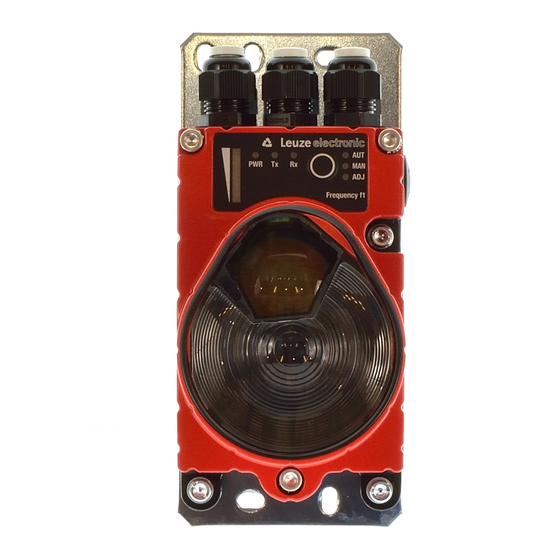
• AUT: operating mode "Automatic" • MAN: operating mode "Manual" • ADJ: operating mode "Adjust" Operating mode button With the operating mode button, you can switch between the three operating modes "Automatic", "Manual" and "Adjust" (see chapter 11.2 "Operating modes"). Leuze electronic DDLS 200... -
Page 64: Operating Modes
To switch to the "Adjust" (ADJ) operating mode, both devices belonging to a transmission path must first be in the "Manual" (MAN) operating mode. It is not possible to switch directly from the "Automatic" to the "Adjust" operating mode or vice versa. DDLS 200 Leuze electronic... -
Page 65: Initial Commissioning
If the data transmission and the alignment are OK through the end of the path of motion, switch both devices back to the "Automatic" (AUT) operating mode by pressing the button for a rela- tively long time (> 2s). The optical data transceiver is now ready for operation. Leuze electronic DDLS 200... -
Page 66: Operation
In the event of an interruption (light beam interruption or switched voltage-free), the DDLS 200 switches off the network to a non-interacting state. The system reactions in the event of an interruption are to be defined together with the supplier of the control system. DDLS 200 Leuze electronic... -
Page 67: Maintenance
The optical window of the DDLS 200 is to be cleaned monthly or as needed (warning output). To clean, use a soft cloth and a cleaning agent (standard glass cleaner). ATTENTION! Do not use solvents and cleaning agents containing acetone. Use of improper cleaning agents can damage the optical window. Leuze electronic DDLS 200... -
Page 68: Diagnostics And Troubleshooting
Each DDLS 200 must be set to diagnostic mode individually. This is in contrast to switching from MAN to ADJ mode, where both DDLS 200 change to ADJ state if the button on one side is pressed. DDLS 200 Leuze electronic... -
Page 69: Troubleshooting
• Operate optical data transceivers with alternating frequency assign- • Influenced by cascading data paths ments, check parallel distances • Intense, direct ambient light • Operate optical data transceivers with alternating frequency assign- ments • Remove ambient light source Leuze electronic DDLS 200... -
Page 70: Accessories
Type designation Comment M12 socket for PWR, axial plug outlet, open cable end, 50104557 K-D M12A-5P-5m-PVC cable length 5 m M12 socket for PWR, axial plug outlet, open cable end, 50104559 K-D M12A-5P-10m-PVC cable length 10 m DDLS 200 Leuze electronic... -
Page 71: Accessories - Ready-Made Cables For Interface Connection
Thread Bare A (N) N.C. N.C. N.C. B (P) M12 connector (B-coded) 1 Conductor with insulation red 2 Conductor with insulation green 3 Drain wire 4 Fibrous fleece Figure 14.1: Cable structure of PROFIBUS connection cable Leuze electronic DDLS 200... -
Page 72: Technical Data For Profibus Connection Cable Kb Pb
M12 connector + M12 socket for PROFIBUS, axial cable outlets, cable length 20 m 50104174 KB PB-25000-SBA M12 connector + M12 socket for PROFIBUS, axial cable outlets, cable length 25 m 50104173 KB PB-30000-SBA M12 connector + M12 socket for PROFIBUS, axial cable outlets, cable length 30 m DDLS 200 Leuze electronic... -
Page 73: Contact Assignment For M12 Ethernet Connection Cable Kb Et
In motion: -25°C ... +60°C (when used with drag chains) Material Cable sheath: PUR (green), wire insulation: foam-PE, Free of halogens, silicone and PVC Bending radius > 65mm, suitable for drag chains Bending cycles > 10 , perm. acceleration < 5m/s Leuze electronic DDLS 200... -
Page 74: Order Codes For M12 Ethernet Connection Cables Kb Et
KB ET - 25000 - SSA 2x M12 connector for BUS IN, axial cable outlets, cable length 25 m 50106905 KB ET - 30000 - SSA 2x M12 connector for BUS IN, axial cable outlets, cable length 30 m DDLS 200 Leuze electronic...
Need help?
Do you have a question about the DDLS 200 Series and is the answer not in the manual?
Questions and answers