Novatel SMART7 Installation And Operation Manual
High performance gnss receiver and antenna
Hide thumbs
Also See for SMART7:
- Installation and operation user manual (35 pages) ,
- Installation and operation user manual (146 pages)
Table of Contents
Advertisement
Quick Links
Advertisement
Table of Contents

Related Manuals for Novatel SMART7


Summary of Contents for Novatel SMART7
- Page 1 SMART7 Installation and Operation User Manual OM-20000181 0C October 2018...
- Page 2 Information in this document is subject to change without notice and does not represent a com- mitment on the part of NovAtel Inc. The software described in this document is furnished under a licence agreement or non-disclosure agreement. The software may be used or copied only in accordance with the terms of the agreement.
-
Page 3: Table Of Contents
2.1 Power Supply Requirements for the SMART7 2.2 Mounting and Orienting the SMART7 2.2.1 Mounting 2.2.2 Orienting 2.2.3 SMART7 and SMART6 Mounting Hole Locations 2.3 Connect the SMART7 to Data Communication Equipment 2.3.1 Serial Ports 2.3.2 Wi-Fi 2.3.3 Ethernet Port 2.3.4 CAN Bus Port 2.4 Connect I/O Signals to the SMART7... - Page 4 4.6.3 ALIGN Azimuth 4.7 Data Collection for Post Processing Chapter 5 Built-In Status Tests 5.1 RXSTATUSEVENT Log 5.2 RXSTATUS Log 5.2.1 Status Word 5.2.2 Error Word 5.2.3 Status Code Arrays 5.2.4 Receiver Status Code SMART7 Installation and Operation User Manual 0C...
- Page 5 5.5.5 Disable Wi-Fi 5.6 SMART7-I and SMART7-W ALIGN Over Wi-Fi Overview 5.6.1 SMART7-I and SMART7-W Automatic Wi-Fi ALIGN Corrections 5.6.2 SMART7-I and SMART7-W Manual Set Up for Wi-Fi Connection between Master and Rover via ICOM1 Chapter 6 Ethernet Configuration 6.1 Required Hardware 6.2 Static IP Address Configuration...
- Page 6 A.3 SMART7 Environmental and Electrical Specifications A.4 SMART7 Data Communication Specifications A.5 SMART7 Strobe Specifications A.6 SMART7 Interface Cable (Optional Accessory) A.0.1 SMART7 Custom Cable Recommendation A.7 SMART7 Mounting Plate Specifications APPENDIX B SMART7 Accessories and Replacement Parts SMART7 Installation and Operation User Manual 0C...
- Page 7 Figure 20: SMART7-S IMU Body Frame with Factory Configured Rotation Figure 21: SMART7-S Installed with Orientation Not Aligned with Vehicle Frame Figure 22: Rear view of SMART7 on a Vehicle – Roof Camber Figure 23: Side View of SMART7 on a Vehicle – Roof Tilt Figure 24: Top View of SMART7 on a Vehicle –...
- Page 8 Figures Figure 40: SMART7 Interface Cable Figure 41: SMART7 Mounting Plate Dimensions (Optional) SMART7 Installation and Operation User Manual 0C...
- Page 9 Table 4: Wi-Fi LED Table 5: Ethernet LED Table 6: Status LED Table 7: SMART7 Serial Port Protocol Table 8: SMART7 Recommended Fuse and Fuse Holders Table 9: Serial Ports Supported Table 10: Inertial Solution Status Table 11: NVM Seed Indication...
-
Page 10: Smart7 Notices
Re-orient or relocate the SMART7 Increase the separation between the equipment and the SMART7 Connect the equipment to an outlet on a circuit different from that to which the SMART7 is connected Consult the dealer or an experienced radio/TV technician for help The SMART7 has been authorized for use in Mobile applications. - Page 11 SMART7 Wi-Fi NovAtel Inc. declares that the SMART7 Wi-Fi transceiver is in compliance with Directive 2014/53/EU (Radio Equipment). The full text of the EU Declaration of Conformity may be obtained from the NovAtel web site at: www.novatel.com/products/compliance/eu-declaration-of-conformity Radio Information Description of Service: Wi-Fi (802.11b/g/n)
- Page 12 (TNV) circuits. WEEE Notice If you purchased your SMART7 product in Europe, please return it to your dealer or supplier at the end of its life. The objectives of the European Community's environment policy are, in par- ticular, to preserve, protect and improve the quality of the environment, protect human health and utilise natural resources prudently and rationally.
- Page 13 SMART7 Notices A warning that actions, operation or configuration may result in regulatory non- compliance, safety issues or equipment damage. SMART7 Installation and Operation User Manual 0C...
-
Page 14: Customer Support
If you are having a hardware problem, send a list of the troubleshooting steps taken and the res- ults. Contact Information Log a support request with NovAtel Customer Support using one of the following methods: Log a Case and Search Knowledge: SMART7 Installation and Operation User Manual 0C... - Page 15 Customer Support Website: www.novatel.com/support Log a Case, Search Knowledge and View Your Case History: (login access required) Web Portal: https://novatelsupport.force.com/community/login E-mail: support@novatel.com Telephone: U.S. and Canada: 1-800-NOVATEL (1-800-668-2835) International: +1-403-295-4900 SMART7 Installation and Operation User Manual 0C...
-
Page 16: Chapter 1 Smart7 Overview
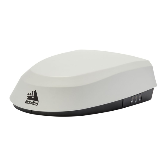
Chapter 1 SMART7 Overview The SMART7 is a high performance GNSS receiver and antenna, capable of receiving and track- ing all current GNSS signals on a maximum of 555 channels. Support for SBAS (Satellite Based Augmentation Systems) is standard and includes WAAS (North America), EGNOS (Europe) and MSAS (Japan). -
Page 17: Smart7 Connectors Overview
Figure 1: SMART7 with Ethernet Model (Back) 1.2 SMART7 Connectors Overview All SMART7 models use the same connector for power and communication. Refer to Table 27: SMART7 Connector Pin Out on page 136 for pin outs. Figure 2: SMART7 Interface Connector The SMART7 Ethernet model has a M12 D-code male connector. -
Page 18: Smart7 Leds
Shell Chassis GND 1.3 SMART7 LEDs The SMART7 has up to three LEDs (model dependent) to indicate receiver status. The following tables provide information about the SMART7 LEDs and their states. Figure 4: SMART7 LEDs Location Table 3: SMART7 Status Indicators... -
Page 19: Table 5: Ethernet Led
Link established Green Slow Flash Active (receiving or transmitting) Table 6: Status LED State Description Green Solid RTK/PPP Solution good or RTK/PPP/INS Solution good Green Slow Flash PPP or RTK Converging Yellow Solid WAAS/Single Point SMART7 Installation and Operation User Manual 0C... -
Page 20: Related Documents And Information
Refer to our web site docs.novatel.com/OEM7 for the latest documentation. This manual does not cover OEM7 service and repair. Contact a local NovAtel dealer for service or repair inquiries (refer to Customer Support on page 14 for contact details). 1.5 SMART7 Emulated Radar 1.5.1 Emulated Radar (ER) -
Page 21: Chapter 2 Smart7 Installation Overview
4. Connect the supplied interface cable to the interface connector on the receiver and then con- nect the power cable to the power supply. Ensure a 5 A slow blow fuse is incorporated in the power wiring. Refer to SMART7 Interface Cable (Optional Accessory) on page 136 and SMART7 Additional Equipment Required on... -
Page 22: Power Supply Requirements For The Smart7
Mount on a secure, stable structure capable of safe operation in the specific environment. If installing on a vehicle, mount the SMART7 on the vehicle roof, ideally close to the pivot point of the vehicle. The SMART7 must be mounted with the connector facing the rear of the vehicle. -
Page 23: Orienting
The SMART7 must be rigidly secured to the vehicle to avoid errors caused by vibration and motion. If installing in a stationary location, mount the SMART7 in a location that has a clear view of the sky so that each satellite above the horizon can be tracked without obstruction. For more... -
Page 24: Connect The Smart7 To Data Communication Equipment
2.3 Connect the SMART7 to Data Communication Equipment The SMART7 can communicate with other devices in the system, such as computers Wi-Fi or Eth- ernet ports. The SMART7 also has a CAN bus port for communication with other CAN bus com- patible devices. -
Page 25: Wi-Fi
2.3.2 Wi-Fi The SMART7 has a Wi-Fi Access Point that is enabled by default. This provides for easy con- nection to any laptop/tablet/smartphone with Wi-Fi capability and a web browser. 1. Once the receiver is installed and powered, use a Wi-Fi capable laptop/tablet/smartphone to locate the SMART7 in the list of detected Wi-Fi Networks and establish a connection. -
Page 26: Can Bus Port
2. Connect the CAN to the CAN Bus (J5) of the SMART7 interface cable, see SMART7 Interface Cable (Optional Accessory) on page 136. The SMART7 CAN bus port is unterminated. If the SMART7 is at the end of the bus, then the connecting cable must have 120 ohms integrated into the cable between CAN1+ and CAN1- in close proximity to the main 14-Pin interface connector. -
Page 27: Check That The Smart7 Is Working
Refer to SMART7 Additional Equipment Required on the next page for fuse recommendations. 2.6 Check that the SMART7 is Working After the SMART7 is installed and powered up, use the following procedure to ensure the receiver is operating. 1. Check that the Status LED Fast Flashes Yellow (ready state). -
Page 28: Smart7 Additional Equipment Required
A computer (user supplied) A cable harness for communicating with and powering the SMART7 (NovAtel SMART7 Inter- face cable is available with four DB-9 connectors, six bare cables and a SMART7 connector (refer to SMART7 Accessories and Replacement Parts on page 139... - Page 29 The Recommended Fuse and Fuse Holders table details the part numbers for recom- mended fuses and fuse holders. These numbers are provided for information only and are not available from NovAtel as separate parts. SMART7 Installation and Operation User Manual 0C...
-
Page 30: Smart7 Operation
SMART7 Operation Before operating the receiver for the first time, refer to SMART7 Installation Overview on page 21 for SMART7 installation instructions. Refer to Communications with the Receiver below to begin configuring the SMART7 for oper- ation. 3.1 Communications with the Receiver... -
Page 31: Table 9: Serial Ports Supported
One method of communicating with the receiver is through a remote terminal. To communicate with the terminal, the receiver requires only the RX, TX and GND lines be used. Ensure the ter- minal’s communications set up matches the receiver’s port settings. SMART7 Installation and Operation User Manual 0C... -
Page 32: Ethernet Communications
Use any standard communications software package that emulates a terminal to establish bidirectional communications with the receiver. Examples include NovAtel Connect and PuTTY. All data is sent as raw 8-bit binary or ASCII characters. -
Page 33: Can Bus Communications
RXSTATUSEVENTA log ONNEW on all ports. See RXSTATUSEVENT Log on page 77 for more details. 2. If NovAtel Connect is unable to locate the OEM7 receiver, use a different COM port to communicate with the receiver. When communication has been established, issue a FRESET STANDARD command. -
Page 34: Transmitting And Receiving Corrections
GNSS receiver that does not know its exact position and requires correction messages from a base station to calculate differential GNSS positions. An example of a dif- ferential setup is shown in Figure 9: Basic Differential Setup on the next page. SMART7 Installation and Operation User Manual 0C... -
Page 35: Figure 9: Basic Differential Setup
To receive corrections, a data link between the base station and the rover station is required. The base and rover stations can both be NovAtel receivers, however NovAtel receivers will work with some other brands. Contact Customer Support for further details (refer to Customer Sup- port on page 14 for details). -
Page 36: Defining Antenna And Base Antenna
(enter your own lat, lon, hgt) log com2 rtcm1004 ontime 1 log com2 rtcm1006 ontime 10 log com2 rtcm1019 ontime 120 saveconfig (optional) RTCM V3 with GLONASS serialconfig com2 19200 N 8 1 N on SMART7 Installation and Operation User Manual 0C... -
Page 37: Rover Station Configuration
RTCMV3 corrections shown in the base and rover examples in Transmitting and Receiv- ing Corrections on page 34. This requires using the INTERFACEMODE command to dedicate one direction of a serial port to one message type only. When the INTERFACEMODE command SMART7 Installation and Operation User Manual 0C... -
Page 38: Align Heading Master And Remote Configurations
51.11358042 -114.04358013 1059.4105 log com2 rtcm1004b ontime 2 1. Interface mode must be set to NOVATEL for the receiver to issue logs with an A or B suffix. 2. Using the receiver in NOVATEL mode consumes more CPU bandwidth than using the native differential messages as shown in Base Station Configuration on page 36. -
Page 39: Manual Set Up Via Com2
3.5.1 Dual-Frequency GLIDE NovAtel’s dual-frequency GLIDE technology adds to the superior pass-to-pass performance provided by single-frequency GLIDE. Dual-frequency GLIDE is ideal for agricultural and machine guidance applications where relative positioning is critical. Using GLIDE significantly reduces the variation in position errors to less than 1 cm from one epoch to the next. -
Page 40: Pdp And Glide Configurations
When the current positioning mode becomes unavailable, the receiver transitions to the next most accurate positioning mode. The setting in the STEADYLINE command determines how the receiver transitions to the next positioning mode. The following sections describe the STEADYLINE modes. SMART7 Installation and Operation User Manual 0C... -
Page 41: Maintain
Once the RTK position is achieved again the receiver will start using the RTK positions for position stability and will slowly transition back to the RTK positions at a default rate of 0.005 m/s or the time specified in the STEADYLINE command. SMART7 Installation and Operation User Manual 0C... -
Page 42: Ual
STEADYLINE operates in Maintain mode while the solution accuracy remains within the Operational limit. B The solution accuracy exceeds the operational limit. The position type changes to WARNING. The STEADYLINE mode changes from Maintain to Prefer Accuracy. SMART7 Installation and Operation User Manual 0C... -
Page 43: Enabling Sbas Positioning
To use the L-Band corrections, an L-Band-capable receiver model and antenna are required (refer to our web site www.nova- tel.com/products/gnss-antennas for information on NovAtel L-Band-capable antennas). For more information on L-Band positioning, refer to: SMART7 Installation and Operation User Manual 0C... -
Page 44: Terrastar Subscriptions
SMART7 Operation NovAtel Application Notes: APN-061: NovAtel CORRECT with PPP using TerraStar Corrections or APN-062 NovAtel CORRECT with Veripos (service dependent) available from www.nova- tel.com/support/search/items/Application%20Note Agriculture Commands and Logs Reference Manual for log/command details and/or visit www.novatel.com/support visit www.novatel.com/products/novatel-correct 3.8.1 TerraStar Subscriptions A subscription is required to use TerraStar service for land, airborne and near shore applic- ations. -
Page 45: Veripos Subscriptions
RTK ASSIST also requires a subscription to the RTK ASSIST service. To obtain a subscription, contact your local NovAtel sales representative or visit www.novatel.com/products/terrastar- gnss-corrections/. The NovAtel Product Serial Number (PSN) is needed to obtain a subscription. The PSN is available from the VERSION log. SMART7 Installation and Operation User Manual 0C... -
Page 46: Logging Using Novatel Connect
NovAtel Connect is a computer program used to configure and monitor NovAtel receivers. The Logging Control Window in NovAtel Connect provides an interface to configure logging and to collect logs from the receiver. The collected logs can be output to one of the receiver com- munication ports or stored on the computer running NovAtel Connect. -
Page 47: Selecting The Logs To Collect
Agriculture Commands and Logs Refer- ence Manual. Destination The destination determines where the log is sent. The log can be sent to any communication port on the receiver or a file on the computer running NovAtel Connect. SMART7 Installation and Operation User Manual 0C... -
Page 48: Start Collecting Logs
1. Click the Stop Recording button. 3.10.5 Change the Log File Settings When logging to a file on the NovAtel Connect computer, the file used is determined by the log file settings. To change the log file settings: 1. Click the button in the Logging Control Window. - Page 49 The file name used for the log file. You can enter a name or allow NovAtel Connect to generate a name. To enter a file name, clear the Auto check box and enter the name in the text box.
-
Page 50: Smart7 With Span Operation
(gyros) so that accelerations along specific axes and angular rotations can be measured. GNSS antenna In the SMART7-S, all of three of these components are included in the SMART7 enclosure. After the SMART7 is installed, the appropriate power supply is attached, and a few simple con- figuration commands are entered, the SPAN system will be ready to navigate. -
Page 51: Definition Of Reference Frames Within Span
The User Output Frame on page 53 4.2.1 The Local-Level Frame (ENU) The definition of the local level coordinate frame is as follows: z-axis – pointing up (aligned with gravity) y-axis – pointing north x-axis – pointing east SMART7 Installation and Operation User Manual 0C... -
Page 52: The Imu Body Frame
The definition of the IMU Body frame is given by the physical axes of the IMU and represents how the sensors are mounted inside the IMU. Refer to SMART7 Mechanical Specifications on page 131 for illustrations of the IMU Body frame axes. -
Page 53: The User Output Frame
IMU into the actual motion of the vehicle. If the SPAN system incorporates other devices, the SPAN system also needs to know the loc- ation and orientation of these additional devices relative to the IMU. SMART7 Installation and Operation User Manual 0C... -
Page 54: Translational Offsets
SMART7-S and a SMART7 in an ALIGN configuration. In this example, the SMART7-S is mounted at rear left corner of the tractor roof and the IMU Body Frame of the SMART7-S (indicated by the small arrows) has the Y axis pointing in the direction of the vehicle motion and the z axis pointing up. -
Page 55: Figure 18: Align Translation Offset
SPAN RBV Calibration procedure. See Body to Vehicle Frame Rotation Cal- ibration Routine on page 71 or Multi-Line Body to Vehicle Frame Rotation Calibration Routine on page 72 for information about this calibration procedure. SMART7 Installation and Operation User Manual 0C... -
Page 56: Rotational Offsets
Y forward through the direction of travel, and X to the right. If the SMART7 is installed with the front of the SMART7 facing the direction of forward motion for the vehicle (as shown in Figure 7: SMART7 Orientation on page 23), an IMU Body frame to Vehicle frame rotation is not required. -
Page 57: Figure 19: Smart7-S Imu Body Frame
At the factory, the following command is entered to configure rotations required to align the IMU Body frame so that the Z axis points up and the Y axis points out the front of the SMART7-S. See Figure 20: SMART7-S IMU Body Frame with Factory Configured Rotation on the next page. -
Page 58: Figure 20: Smart7-S Imu Body Frame With Factory Configured Rotation
Figure 20: SMART7-S IMU Body Frame with Factory Configured Rotation If SMART7-S is not installed with the front of the SMART7-S facing the direction of vehicle travel, a different set of rotations must be entered using the SETINSROTATION RBV command. -
Page 59: Figure 21: Smart7-S Installed With Orientation Not Aligned With Vehicle Frame
SMART7 with SPAN Operation Figure 21: SMART7-S Installed with Orientation Not Aligned with Vehicle Frame In this example, the Euler Angles to rotate from the IMU Body frame (Figure 19: SMART7-S IMU Body Frame on page 57) to the Vehicle frame (RBV) are:... - Page 60 The rotational offsets are entered using the SETINSROTATION command. For this example, the command to enter the rotations for the previous example is: SETINSROTATION RBV 0 180 0 SMART7 Installation and Operation User Manual 0C...
-
Page 61: Importance Of Rbv Calibration
SMART7 with SPAN Operation 4.3.3 Importance of RBV Calibration For the SMART7 to provide the best performance, the rotation offset of the IMU body to the Vehicle frame (RBV) should be known as accurately as possible. Since constraints happen at the vehicle level, any error in the offset will translate into worse performance. -
Page 62: Software Configuration
On a SPAN system, both the GNSS receiver and the IMU must be configured. 4.4.1 Minimum Recommended Configuration When configuring your SMART7 SPAN system for first time use, the following is the minimum amount of information required to ensure proper operation of a SPAN system. -
Page 63: Gnss Configuration
4.4.2 GNSS Configuration The GNSS configuration can be set up for different accuracy levels such as single point, SBAS, DGPS, PPP and RTK. Refer to the SMART7 Operation on page 30 for details on DGPS, RTK, L- Band or SBAS setup and operation. -
Page 64: Real-Time Operation
Routine on page 71. SPAN Configuration with NovAtel Connect NovAtel Connect provides a wizard that takes you through the steps required to configure a SPAN system. For information about using the SPAN Configuration wizard in NovAtel Connect, refer to the help file available within NovAtel Connect. -
Page 65: Table 10: Inertial Solution Status
DETERMINING_ INS is determining the IMU axis aligned with gravity. ORIENTATION WAITING_ The INS filter has determined the IMU orientation and is awaiting an INITIALPOS initial position estimate to begin the alignment process. SMART7 Installation and Operation User Manual 0C... -
Page 66: System Start-Up And Alignment Techniques
SPAN filter as the initial system heading. For the kinemtic alignment routine to work optimally, the course-over-ground azimuth must not include any bias from the defined Vehicle Frame. (For example, a plane being blown in the wind SMART7 Installation and Operation User Manual 0C... -
Page 67: Ins Seed / Fast Ins Initialization
The rotation from the IMU Body frame to the Vehicle frame (RBV) must be set to enable kin- ematic alignment. In order to simplify this configuration it is strongly suggested that you mount the IMU in parallel to the vehicle frame. The SMART7 should be oriented as shown in SMART7 Orientation on page 23. - Page 68 Apart from injecting the seed at startup without validation, this will also remove some requirements typically asserted to allow the filter to converge. This will allow the system to run without GNSS adequately at startup. Example Usage Enabling functionality after FRESET: SMART7 Installation and Operation User Manual 0C...
-
Page 69: Table 11: Nvm Seed Indication
NVM Seed is pending validation (awaiting GNSS) 0x04 NVM Seed Injected (includes error model data) NVM Seed data ignored due to a user-commanded filter reset or 0x05 configuration change 0x06 NVM Seed error model data injected SMART7 Installation and Operation User Manual 0C... -
Page 70: Navigation Mode
The inertial solution is available up to a rate of 200 Hz. Data can be requested at a specific syn- chronous time interval, asynchronously matching the IMU output rate, or can be triggered by the mark input trigger at rates up to 200 Hz. SMART7 Installation and Operation User Manual 0C... -
Page 71: Body To Vehicle Frame Rotation Calibration Routine
Specific logs need to be collected for post-processing. See Data Collection for Post Processing on page 76. To store data from an OEM7 receiver, connect the receiver to a computer running NovAtel Con- nect or other terminal program capable of recording data. -
Page 72: Multi-Line Body To Vehicle Frame Rotation Calibration Routine
For applications where vehicle roll must be well known, or pass-to-pass accuracy of a highly offset position is especially important, the Multi-Line IMU Body to Vehicle frame offset calibration routine offers higher SMART7 Installation and Operation User Manual 0C... -
Page 73: Figure 25: Multi-Line Imu Body To Vehicle Calibration
To monitor the calibration, log INSCALSTATUS using the ONCHANGED trigger. 7. When the end of the available distance is reached, stop the vehicle. Halt the ongoing cal- ibration by sending the INSCALIBRATE command again: SMART7 Installation and Operation User Manual 0C... -
Page 74: Azimuth Sources On A Span System
This effect is known as the crab angle. Course over ground azimuth is a great way to compute the offset if another means of computing the vehicle azimuth is available. SMART7 Installation and Operation User Manual 0C... -
Page 75: Inertial Azimuth
GNSS or INS HEADING2 NovAtel ALIGN INSATT / INSATTS / NovAtel Inertial INSATTX INSPVA / INSPVAS / NovAtel Inertial INSPVAX Course Over Ground INSSPD NovAtel Computed using the INS solution only PASHR NMEA Inertial SMART7 Installation and Operation User Manual 0C... -
Page 76: Data Collection For Post Processing
HEADING2B ONNEW (if using ALIGN dual antenna solution) ® Post processing is performed through the Waypoint Inertial Explorer software package avail- able from the NovAtel Waypoint Products Group. Visit our Web site at www.novatel.com details. The highest rate that you should request GNSS logs (RANGE, BESTPOS, RTKPOS, PSRPOS, and so on) while in INS operation is 5 Hz. -
Page 77: Chapter 5 Built-In Status Tests
5.2.1 Status Word The status word is the third field after the header, as shown in the example in Figure 26: Loca- tion of Receiver Status Word below. Figure 26: Location of Receiver Status Word SMART7 Installation and Operation User Manual 0C... -
Page 78: Error Word
Figure 28: Location of Receiver Error Word Figure 29: Reading the Bits in the Receiver Error Word below shows an example of a receiver error word. Figure 29: Reading the Bits in the Receiver Error Word SMART7 Installation and Operation User Manual 0C... -
Page 79: Status Code Arrays
Bit 31 of the receiver status word indicates the condition of all SMART7 Installation and Operation User Manual 0C... -
Page 80: Set And Clear Mask For All Status Code Arrays
Any bit set in the error word results in a RXSTATUSEVENT log broadcast (unless unlogged). Refer also to the RXSTATUS log in the Agriculture Commands and Logs Reference Manual for a more detailed description. SMART7 Installation and Operation User Manual 0C... -
Page 81: Smart7-I And Smart7-W Wi-Fi Configuration Overview
5.3 Wi-Fi Modes 5.3.1 Access Point (AP) AP is the Wi-Fi default mode at start up. This mode is used by the SMART7 to wirelessly connect to devices defined as clients or concurrent. Refer to Enable the Wi-Fi Client on page 83 for detailed instructions. -
Page 82: Smart7-I And Smart7-W Wi-Fi Modes
This ensures the changes are kept when the receiver is restarted. The SMART7 has the ability to override the Access Point SSID to the existing Access Point. By default, the SSID is the enclosure PSN prefixed by 'SM7-' (e.g. SM7-NMPX17500010L). Refer to Change the SSID on page 86 for detailed instructions. -
Page 83: Enable The Wi-Fi Client
The information for up to four Access Points can be stored in the SMART7 using the WIFINETCONFIG command. To configure the SMART7 as a client and connect it to an access point, follow these steps: 1. Start a command line interface (CLI) session with the receiver. -
Page 84: Enable The Wi-Fi Concurrent
Ethernet or through the Access Point to which it is con- nected. This can be problematic if none of the access points stored in the SMART7 receiver are in range. To ensure the receiver is accessible over a Wi-Fi connection, it is possible to configure it in Concurrent mode, which allows it to operate as both an access point (for con- figuration/monitoring purposes) and as a Client (for the transfer of corrections). -
Page 85: Smart7-I And Smart7-W Wi-Fi Changes
3. Use the WIFIMODE command to restart the Wi-Fi transceiver. WIFIMODE AP 4. Use the SAVECONFIG command to store the change in Non-Volative Memory. This ensures the new passkey is kept when the receiver is restarted. SMART7 Installation and Operation User Manual 0C... -
Page 86: Change The Ssid
5.5.2 Change the SSID Use the WIFIAPSSID command to change the default SSID if required. WIFIAPSSID <ssid> Issue the SAVECONFIG command and restart the SMART7 to change the SSID. 5.5.3 Change the Wi-Fi Channel 1. Start a CLI session with the receiver. -
Page 87: Smart7-I And Smart7-W Align Over Wi-Fi Overview
5.6.1 SMART7-I and SMART7-W Automatic Wi-Fi ALIGN Corrections The WIFIALIGNAUTOMATION command is provided to simplify configuration of a pair of NovAtel Wi-Fi enabled receivers, one acting as an ALIGN Master and one acting as an ALIGN Rover. The ALIGN Rover, acting as a Wi-Fi Client, connects to the specified Wi-Fi Access Point and con- figures it as the ALIGN Master. -
Page 88: Smart7-I And Smart7-W Manual Set Up For Wi-Fi Connection Between Master And Rover Via Icom1
INTERFACEMODE ICOM5 NOVATELX NOVATEL OFF LOG ICOM5 HEADINGEXTB ONNEW 5.6.2 SMART7-I and SMART7-W Manual Set Up for Wi-Fi Connection between Master and Rover via ICOM1 In this setup, the ALIGN Rover acts as a Wi-Fi Client to the ALIGN Master which, by default, is configured as a Wi-Fi Access Point. - Page 89 It can take several seconds for the IP parameters to be set. wifinetconfig 1 enable "PwrPak7-NMND17190003B" "12345678" dhcp wifimode client icomconfig icom1 tcp 192.168.19.1:3001 interfacemode icom1 novatelx novatel off log icom1 headingext2b onnew hdtoutthreshold 1.0 log headinga onnew saveconfig SMART7 Installation and Operation User Manual 0C...
- Page 90 DNS server. wifinetconfig 1 enable "PwrPak7-NMND17190003B" "12345678" static 192.168.19.42 255.255.255.0 192.168.19.1 192.168.19.1 wifimode client icomconfig icom1 tcp 192.168.19.1:3001 interfacemode icom1 novatelx novatel off log icom1 headingext2b onnew hdtoutthreshold 1.0 log headinga onnew saveconfig SMART7 Installation and Operation User Manual 0C...
-
Page 91: Chapter 6 Ethernet Configuration
The Ethernet port connections for a computer connected to the receiver are also described for Windows 7 operating systems. In this chapter, references to OEM7 receivers includes the SMART7-I. The SAVEETHERNETDATA command can be issued to retain the Ethernet configuration settings after a RESET/FRESET command. -
Page 92: Static Ip Address Configuration-Receiver
1. Connect a computer to the OEM7 receiver using a null modem serial cable. 2. Establish a connection to the receiver using either NovAtel Connect or another terminal pro- gram. This connection is used to send the commands in this procedure to the receiver. -
Page 93: Static Ip Address Configuration-Windows 7
See Figure 31: Cross-Over Ethernet Cable Configuration—OEM7 Receiver on the previous page. 2. Connect to the receiver using NovAtel Connect or any third party terminal program that sup- ports TCP/IP connections. Use the static IP address and port number assigned to the OEM7 receiver in Static IP Address Configuration—Receiver on the previous page. -
Page 94: Dynamic Ip Address Configuration
1. Connect a computer to the OEM7 receiver using a null modem serial cable or USB cable (model dependent). 2. Establish a connection to the receiver using either NovAtel Connect or another terminal pro- gram. This connection is used to send the commands in this procedure to the receiver. -
Page 95: Figure 33: Base/Rover Ethernet Setup-Oem7 Receiver
1. Connect your computer to both OEM7 receivers using null modem serial cables or USB cables. 2. Establish a connection to the receiver using either NovAtel Connect or another terminal pro- gram. This connection is used to send the commands in this procedure to the receivers. -
Page 96: Large Ethernet Port Data Throughput
If done incorrectly, changing the Windows Registry may impair the operation of the computer. Editing the Windows Registry is for advanced Microsoft Windows users only. NovAtel Inc. is not able to provide any technical support for any actions taken regarding information found in Microsoft’s Knowledge Base. -
Page 97: Figure 34: Ntrip System
NTRIP servers and NTRIP clients. The NTRIP caster is provided by third party sources. For a full list of NTRIP casters, refer to the following link: http://www.rtcm-ntrip.org/home. The following procedure describes how to configure a NovAtel base and a NovAtel rover through a third party NTRIP caster. This configuration is recommended for optimal RTK performance. - Page 98 INTERFACEMODE NCOM1 RTCA NONE OFF RTKSOURCE AUTO ANY PSRDIFFSOURCE AUTO ANY LOG BESTPOS ONTIME 1 (optional) SAVECONFIG Refer to the NTRIPCONFIG command in the Agriculture Commands and Logs Reference Manual for further command details. SMART7 Installation and Operation User Manual 0C...
-
Page 99: Chapter 7 Can Bus
The SMART7 has internal CAN transceivers, however they still require proper bus terminations. Refer to Table 27: SMART7 Connector Pin Out on page 136 for pin-out information. OEM7 receivers support the following NMEA2000 Parameter Group Messages (PGN) over the CAN bus:... -
Page 100: Default Configuration
3. Optionally, use the J1939STATUS log to monitor CAN status on the receiver. 7.2.1 Configuration Notes The J1939CONFIG and CANCONFIG commands can be entered in any order. After the CANCONFIG command is used to place the receiver on the CAN bus, J1939CONFIG SMART7 Installation and Operation User Manual 0C... -
Page 101: Example Of Enabling The Can Bus
7.2.4 Example of Detecting an Address Claim Failure and Reconfiguring 1. LOG J1939STATUS ONCHANGED 2. J1939CONFIG NODE1 CAN1 <addresses> 3. CANCONFIG CAN1 ON < J1939STATUS NODE1 DISABLED 0 0xFE < J1939STATUS NODE1 CLAIMING 1 <address> SMART7 Installation and Operation User Manual 0C... -
Page 102: Address Claim Procedure
J1939CONFIG command. 7.3 NMEA2000 Logging OEM7 receivers support both a subset of the standard NMEA2000 PGNs, as well as NovAtel pro- prietary PGNs. All NMEA2000 logs are configured using the LOG command, where the COM port is a CAN port (CCOM). -
Page 103: Example Of Nmea2000 Log Configuration
It is strongly recommended to RESET the receiver after using the PGNCONFIG com- mand. This prevents PGN ambiguities and conflicts. 7.4 Corrections Over CAN All NovAtel supported correction types are supported over CAN ports (CCOM). To send or receive corrections: 1. Configure the CAN Bus. See Configuring the CAN Bus on page 100. -
Page 104: Example For Receiving Corrections From Any Source
The CCOM port requires special configuration and has the following limitations: A single CCOM port cannot be used for both Binary and ASCII / NovAtel ASCII messages. A single CCOM port cannot be used for both Binary messages and corrections. -
Page 105: Configuration On Oem6
The J1939CONFIG command can be used to modify the default address claim parameters including the ManufacturingCode (set to 603 in the SETCANNAME example above, now defaults to 305 in the new J1939CONFIG) but it's not necessary. SMART7 Installation and Operation User Manual 0C... -
Page 106: Chapter 8 Troubleshooting
Try to resolve the problem using the troubleshooting guide in Table 16: Troubleshooting Based on Symptoms below, then try our Knowledge Base at www.novatel.com/support/. If you are still not able to resolve the problem, see Customer Support on page 14 for troubleshooting logs and contact information. -
Page 107: Examining The Rxstatus Log
The receiver is being affected by Move the receiver away from any possible jamming sources jamming Go to the Interference Toolkit section in the NovAtel Documentation portal: docs.novatel.com/OEM7. Move the GNSS antenna away from the source of the The receiver is being affected by interference signal. -
Page 108: Table 17: Resolving A Receiver Error Word
Check the VERSION log. The VERSION log will indicate "Invalid authcode". Upgrade the auth-code as described in Upgrading Using the AUTH Command on page 125 Issue a FRESET command Power Supply Requirements for the SMART7 on page 22 Reserved Check the temperature ranges in: The operating temperatures are ambient air temperatures. -
Page 109: Table 18: Resolving An Error In The Receiver Status Word
Check the temperature ranges in SMART7 Environmental and Electrical Specifications on page 133 Power Supply Requirements for the SMART7 on page 22 For SMART7, contact Customer Support on page 14 Check the CPU idle time. Check for unnecessary logging. Check for simultaneous use of functionality. -
Page 110: Examining The Aux1 Status Word
AUX1 status word. Table 19: Resolving an Error in the AUX1 Status Word Bit Set Action to Resolve Jammer detected None. This bit indicates that Position Averaging is ON Jammer detected SMART7 Installation and Operation User Manual 0C... -
Page 111: High Temperature Environments
Action to Resolve Connect the receiver via USB (not applicable to SMART7) 8-10 Reduce the amount of logging on the USB ports (not applicable to SMART7) (Reserved bit) None. This bit indicates a Profile set using the PROFILE command is activated. -
Page 112: Recovering From A Temperature Status Error
3. Log the HWMONITOR log and check the two temperature status fields (0x01 and 0x16). LOG HWMONITOR ontime 30 <HWMONITOR USB1 0 77.5 FINESTEERING 1990 326851.000 0a104020 52db 14434 < 10 (Temperature 0x01) < 58.424915314 100 < 0.000122100 200 < 3.296703339 600 < 5.169230938 700 < 1.192307711 800 SMART7 Installation and Operation User Manual 0C... -
Page 113: Safe Mode
GNSS satellites. 8.4.2 Recovery Steps If the Safe Mode error bit or the Reset Loop Detected warning bit are set in the RXSTATUS log, take the following steps to diagnose and recover the system: SMART7 Installation and Operation User Manual 0C... - Page 114 2. Reference Table: Safe Mode States in the Agriculture Commands and Logs Reference Manual and find the suggested actions for the current Safe Mode State. 3. If the suggested actions do not resolve the issue, contact NovAtel Customer Support. SMART7 Installation and Operation User Manual 0C...
-
Page 115: Chapter 9 Novatel Firmware And Software
(support@novatel.com) for details on custom loader requirements. 9.1.2 Model Upgrades Model upgrades enable purchased receiver features. Contact a local NovAtel dealer to assist in selecting the upgrade options that best suit your GNSS needs at www.novatel.com/where-to-buy. Contact NovAtel Customer Support www.nova-... -
Page 116: Authorization Code
The date is the last day that the auth-code is valid and expires at the end of day, UTC time. Once the trial period has expired, a new auth-code will need to be obtained from NovAtel Cus- tomer Support (support@novatel.com). -
Page 117: Updating Or Upgrading Using The Winload Utility
All of the firmware available on the downloads website are packaged in .zip files with the fol- lowing name: OEM7XXX.zip for firmware to be installed on OEM7 receivers NovAtel Customer Service may generate and provide the required authorization code. Author- ization codes are obtained by contacting support@novatel.com or at www.novatel.com/support/. -
Page 118: Figure 35: Winload's Open Window
Figure 35: WinLoad’s Open Window When a file is selected, the filename appears in the main WinLoad display area and in the title bar (Figure 36: Open File in WinLoad below). Figure 36: Open File in WinLoad SMART7 Installation and Operation User Manual 0C... -
Page 119: Updating Using Softload Commands
The receiver stops tracking GNSS satellites during the SoftLoad process. Do not attempt to SoftLoad when GNSS satellite tracking on the unit is required. If the unit is connected to the NovAtel Connect utility, only the Console and ASCII Message windows may remain open in the Connect Utility. -
Page 120: Working With S-Records
S70000 S70500000000FA Records beginning with S3 contain the actual firmware image data. Aside from the header, each pair of characters forms the ASCII representation of a binary byte. The format is as follows: SMART7 Installation and Operation User Manual 0C... -
Page 121: Sending Firmware Data
Agriculture Commands and Logs Reference Manual for command details. The *.shex file data may contain many gaps and jumps. For example, in many NovAtel *.shex files, data for address 0x000_00000 is stored near the very end of the file. Example Packaging Multiple S3 Records In A SOFTLOADDATA Command... -
Page 122: Softload Update Method
Previous Address + Previous Num Bytes = 0x00000000 + 0x1C = 0x0000001C Add data to existing SOFTLOADDATA command The SOFTLOADDATA command must be sent as a NovAtel binary format command. 9.4.4 SoftLoad Update Method This section describes the sequence of commands that are issued to the receiver when updating using a *.shex file. - Page 123 The SoftLoad process can be safely canceled at any time using the SOFTLOADRESET command or by otherwise resetting the receiver. Once the COMPLETE status is reported by SOFTLOADSTATUS, the new firmware image will be run after the receiver is reset. SMART7 Installation and Operation User Manual 0C...
- Page 124 Chapter 9 NovAtel Firmware and Software SMART7 Installation and Operation User Manual 0C...
-
Page 125: Softload Errors
NovAtel Customer Support. The upgrade can be performed directly through the NovAtel Connect command line or from any other communications program. Refer to Format of Firmware Files on page 117 for details on updating versus upgrading. 9.5.1 Upgrade Procedure 1. - Page 126 Chapter 9 NovAtel Firmware and Software If communicating using NovAtel Connect, the communication path must be closed and reopened using the Device menu. SMART7 Installation and Operation User Manual 0C...
-
Page 127: Appendix A Smart7 Technical Specifications
SMART7 Environmental and Electrical Specifications on page 133 SMART7 Data Communication Specifications on page 134 SMART7 Strobe Specifications on page 134 For information about the cable available for the SMART7, see the following: SMART7 Interface Cable (Optional Accessory) on page 136 SMART7 Installation and Operation User Manual 0C... -
Page 128: Smart7 Performance Specifications
A.1 SMART7 Performance Specifications All specifications subject to GNSS system characteristics. These specifications apply to the SMART7 and SMART7-S. Table 21: SMART7 Receiver Performance 2.4 m L1 only 1.5 m Single Point 2.0 m L1/L2 1.2 m 0.6 m SBAS 0.4 m... - Page 129 These specifications refer to the processing power of the GNSS receiver. The receiver shall have the processing power to track at least 44 satellites (if visible) and be able to use the observations from 52 satellites to compute the position. SMART7 Installation and Operation User Manual 0C...
-
Page 130: Table 22: Smart7-S Imu Performance
Signal Reacquisition <1.0 s typical Time Accuracy 20 ns RMS Velocity Accuracy <0.03 m/s RMS The IMU performance specifications apply to the SMART7-S only. Table 22: SMART7-S IMU Performance Gyroscope Performance Input Rate (max) ±150 °/second Bias Repeatability 0.5 °/second Bias Instability 3.5 °/hour... -
Page 131: Smart7 Mechanical Specifications
APPENDIX A SMART7 Technical Specifications A.2 SMART7 Mechanical Specifications Figure 38: SMART7 Dimensions below Figure 39: SMART7-S Center of Navigation on the next page Figure 38: SMART7 Dimensions Dimensions are in millimetres. SMART7 Installation and Operation User Manual 0C... -
Page 132: Figure 39: Smart7-S Center Of Navigation
APPENDIX A SMART7 Technical Specifications Figure 39: SMART7-S Center of Navigation SMART7 Installation and Operation User Manual 0C... -
Page 133: Smart7 Environmental And Electrical Specifications
APPENDIX A SMART7 Technical Specifications A.3 SMART7 Environmental and Electrical Specifications These specifications apply to the SMART7, SMART7-I, SMART7-W and SMART7-S. Table 23: SMART7 Environmental Specifications Operating Temperature -40°C to +70°C Storage Temperature -45°C to +80°C Humidity MIL-STD-810G(CH1), Method 507.6 Immersion MIL-STD-810G(CH1), Method 512.6... -
Page 134: Smart7 Data Communication Specifications
TKIP, AES CCMP A.5 SMART7 Strobe Specifications All of the SMART7 strobe signals are available on the 14-Pin Interface connector. Pulse Per Second (PPS) strobes provide synchronization signal. Refer to SMART7 Interface Cable (Optional Accessory) on page 136 for pin out details. -
Page 135: Table 26: Smart7 Strobes Description
Table 26: SMART7 Strobes Description Strobes Input/Output Comment Emulated 0VDC to VBATT+ (also refer to SMART7 Interface Cable (Optional Output Radar (ER) Accessory) on the next page) 3.3V CMOS A time synchronization output. This is a pulse where the leading Output edge is synchronized to receiver calculated GNSS Time. -
Page 136: Smart7 Interface Cable (Optional Accessory)
The NovAtel part number for the SMART7 interface cable is 01019944. This cable provides access to all of the signals available on the SMART7 14-pin Tyco Ampseal connector. The exposed wires (BATT+ and BATT-) can then be connected to a vehicular power circuit (or equi- valent) protected by a 5 A slow blow fuse (user supplied). -
Page 137: Smart7 Custom Cable Recommendation
Load= 3K Ohm Minimum A.0.1 SMART7 Custom Cable Recommendation To create a custom cable for the J1 port, a specific connector is required on the SMART7 end of the cable. See the following table for information about this connector. Table 29: I/O Connector... -
Page 138: Smart7 Mounting Plate Specifications
The optional SMART7 mounting plate is NovAtel part number 1020089. The optimal screw pen- etration into the SMART7 mounting holes is 6 mm (±1 mm) deep. When selecting screws for mounting the SMART7, ensure the screw penetration does not exceed this specification. Using excessively long screws can damage the SMART7 enclosure. -
Page 139: Appendix B Smart7 Accessories And Replacement Parts
APPENDIX B SMART7 Accessories and Replacement Parts The following tables list the replacement parts available for your NovAtel SMART7 receiver. For assistance or to order additional components, contact your local NovAtel dealer or NovAtel Cus- tomer Support. Table 30: SMART7 Products... - Page 140 SMART7 Installation and Operation User Manual 0C...
Need help?
Do you have a question about the SMART7 and is the answer not in the manual?
Questions and answers