Novatel SMART7 Installation And Operation User Manual
Hide thumbs
Also See for SMART7:
- Installation and operation manual (140 pages) ,
- Installation and operation user manual (146 pages)

Related Manuals for Novatel SMART7


Summary of Contents for Novatel SMART7
- Page 1 SMART7 Installation and Operation User Manual Preliminary 3 OM-20000181 0A June 2018...
- Page 2 Information in this document is subject to change without notice and does not represent a com- mitment on the part of NovAtel Inc. The software described in this document is furnished under a licence agreement or non-disclosure agreement. The software may be used or copied only in accordance with the terms of the agreement.
-
Page 3: Table Of Contents
2.1 Power Supply Requirements for the SMART7 2.2 Mounting and Orienting the SMART7 2.2.1 Mounting 2.2.2 Orienting 2.3 Connect the SMART7 to Data Communication Equipment 2.3.1 Wi-Fi 2.3.2 Ethernet Port 2.3.3 CAN Bus Port 2.4 Connect I/O Signals to the SMART7 2.5 Connect Power to the SMART7... - Page 4 Figures Figures Figure 1: SMART7 with Ethernet Model Figure 2: SMART7 Interface Connector Figure 3: SMART7 Ethernet Connector (model dependent) Figure 4: SMART7 LEDs Location Figure 5: SMART7 Installation Figure 6: SMART7 Magnetic Mounting Plate Figure 7: SMART7 Orientation Figure 8: SMART7 Dimensions...
- Page 5 Table 10: SMART7 Environmental Specifications Table 11: SMART7 Power Requirements Table 12: Data Communications Interfaces Table 13: SMART7 Strobes Description Table 14: SMART7 Connector Pin Out Table 15: 14-Pin Interface Connector Preliminary 3 SMART7 Installation and Operation User Manual 0A...
-
Page 6: Smart7 Notices
Re-orient or relocate the SMART7 Increase the separation between the equipment and the SMART7 Connect the equipment to an outlet on a circuit different from that to which the SMART7 is connected Consult the dealer or an experienced radio/TV technician for help The SMART7 has been authorized for use in Mobile applications. - Page 7 SMART7 Wi-Fi NovAtel Inc. declares that the SMART7 Wi-Fi transceiver is in compliance with Directive 2014/53/EU (Radio Equipment). The full text of the EU Declaration of Conformity may be obtained from the NovAtel web site at: www.novatel.com/products/compliance/eu-declaration-of-conformity Radio Information Description of Service: Wi-Fi (802.11b/g/n)
- Page 8 RoHS The SMART7 is in conformity with Directive 2011/65/EU of the European Parliament and of the council of 8 June 2011 on the restriction of the use of certain hazardous substances in electrical and electronic equipment.
-
Page 9: Customer Support
If you are having a hardware problem, send a list of the troubleshooting steps taken and the res- ults. Contact Information Log a support request with NovAtel Customer Support using one of the following methods: Log a Case and Search Knowledge: Preliminary 3... - Page 10 Customer Support Website: www.novatel.com/support Log a Case, Search Knowledge and View Your Case History: (login access required) Web Portal: https://novatelsupport.force.com/community/login E-mail: support@novatel.com Telephone: U.S. and Canada: 1-800-NOVATEL (1-800-668-2835) International: +1-403-295-4900 Preliminary 3 SMART7 Installation and Operation User Manual 0A...
-
Page 11: Chapter 1 Smart7 Overview
Chapter 1 SMART7 Overview The SMART7 is a high performance GNSS receiver and antenna, capable of receiving and track- ing all current GNSS signals on a maximum of 555 channels. SBAS (Satellite Based Aug- mentation Systems) includes WAAS (North America), EGNOS (Europe) and MSAS (Japan). SBAS support is standard. -
Page 12: Smart7 Connectors Overview
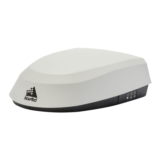
Figure 1: SMART7 with Ethernet Model 1.2 SMART7 Connectors Overview All SMART7 models use the same connector for power and communication. Refer to Table 14: SMART7 Connector Pin Out on page 33 for cable dimensions and pin outs. Figure 2: SMART7 Interface Connector The SMART7 Ethernet model has a M12 D-code female. -
Page 13: Smart7 Leds
Shell Chassis GND 1.3 SMART7 LEDs The SMART7 has up to three LEDs (model dependent) to indicate receiver status. The following tables provide information about the SMART7 LEDs and their states. Figure 4: SMART7 LEDs Location Table 3: SMART7 Status Indicators... -
Page 14: Table 4: Wi-Fi Led
Yellow Slow Flash (1 Hz) Tracking Yellow Fast Flash (3 Hz) Initialized (ME_READY) Red Solid Power On/Error/Reset Red Slow Flash (1 Hz) Position Error Red Fash Flash (3 Hz) Solution Error Preliminary 3 SMART7 Installation and Operation User Manual 0A... -
Page 15: Smart7 Emulated Radar
This is often used in agricultural applications such as planting and spraying. The SMART7 eliminates the need for separate ground-sensing radar equipment by converting the GPS-derived velocity to proportional frequency output. -
Page 16: Example Of Enabling The Can Bus
1.5.5 Address Claim Procedure To become operational on the CAN bus, an OEM7 receiver must claim a J1939 address. The pre- ferred address and a range of alternative addresses are specified using the J1939CONFIG Preliminary 3 SMART7 Installation and Operation User Manual 0A... - Page 17 CLAIMING followed by CLAIMED. Restarting CAN using the J1939CONFIG command or CANCONFIG command clears the commanded address; the Address Claim procedure will be executed again based on parameters specified in the J1939CONFIG command. Preliminary 3 SMART7 Installation and Operation User Manual 0A...
-
Page 18: Chapter 2 Smart7 Installation Overview
4. Connect the supplied interface cable to the interface connector on the receiver and then con- nect the power cable to the power supply. Ensure a 5 A slow blow fuse is incorporated in the power wiring. Refer to SMART7 Interface Preliminary 3... -
Page 19: Power Supply Requirements For The Smart7
Mount on a secure, stable structure capable of safe operation in the specific environment. If installing on a vehicle, mount the SMART7 on the vehicle roof, ideally close to the pivot point of the vehicle. The SMART7 must be mounted with the connector facing the rear of the vehicle. -
Page 20: Orienting
The SMART7 must be rigidly secured to the vehicle to avoid errors caused by vibration and motion. If installing in a stationary location, mount the SMART7 in a location that has a clear view of the sky so that each satellite above the horizon can be tracked without obstruction. For more... -
Page 21: Connect The Smart7 To Data Communication Equipment
1. Once the receiver is installed and powered, use a Wi-Fi capable laptop/tablet/smartphone to locate the SMART7 in the list of detected Wi-Fi Networks and establish a connection. The SMART7 SSID is printed on a label on the bottom of the receiver. The format of the SSID is SMART7-<Receiver PSN>, e.g. "SMART7-ABCDEF1234567". -
Page 22: Can Bus Port
2. Connect the CAN leads to the CAN Bus. The SMART7 CAN bus port is unterminated. If the SMART7 is at the end of the bus, then the connecting cable must have 120 ohms integrated into the cable between CANH and CANL in close proximity to the main 14-Pin interface connector. -
Page 23: Check That The Smart7 Is Working
Refer to SMART7 Additional Equipment Required for fuse recommendations. 2.6 Check that the SMART7 is Working After the SMART7 is installed, powered up and use the following procedure to ensure the receiver is operating. 1. Check that the Status LED Fast Flashes Yellow (in the ME_READY state). - Page 24 4. Check the Receiver Status word (02004020 in this example). If the lowest bit (bit 0) is set, the receiver has errors. For information about the other digits in Receiver Status word, refer to the RXSTATUS log in the OEM7 Commands and Logs Reference Manual. Preliminary 3 SMART7 Installation and Operation User Manual 0A...
-
Page 25: Appendix A Smart7 Technical Specifications
SMART7 Environmental and Electrical Specifications on page 30 SMART7 Data Communication Specifications on page 31 OEM7700 Strobe Specifications For information about the cable available for the SMART7, see the following: SMART7 Interface Cable on page 33 Preliminary 3 SMART7 Installation and Operation User Manual 0A... -
Page 26: Smart7 Performance Specifications
A.1 SMART7 Performance Specifications All specifications subject to GNSS system characteristics. These specifications apply to the SMART7 and SMART7-SPAN. Table 8: SMART7 Receiver Performance 2.4 m L1 only 1.5 m Single Point 2.0 m L1/L2 1.2 m 0.6 m SBAS 0.4 m... - Page 27 E1, E5 AltBOC, E5a, E5b (optional) NavIC (IRNSS) SBAS QZSS L1, L2 L-Band Up to 5 channels L2 P for GLONASS L2 C/A for GLONASS. Currently the receiver can track up to 3 L-Band channels. Preliminary 3 SMART7 Installation and Operation User Manual 0A...
-
Page 28: Table 9: Smart7 Imu Performance
Signal Reacquisition <1.0 s typical Time Accuracy 20 ns RMS Velocity Accuracy <0.03 m/s RMS The IMU performance specifications apply to the SMART7 only. Table 9: SMART7 IMU Performance Gyroscope Performance Input Rate (max) ±150 °/second Bias Repeatability 0.5 °/second Bias Instability 3.5 °/hour... -
Page 29: Smart7 Mechanical Specifications
APPENDIX A SMART7 Technical Specifications A.2 SMART7 Mechanical Specifications Figure 8: SMART7 Dimensions below Figure 9: SMART7-SPAN Center of Navigation below Figure 8: SMART7 Dimensions Dimensions are in millimetres. Figure 9: SMART7-SPAN Center of Navigation Preliminary 3 SMART7 Installation and Operation User Manual 0A... -
Page 30: Smart7 Environmental And Electrical Specifications
These values can change with the number of satellites in view, firmware version, data logging rates and features in use. Use them as a guide for what you might expect but not as absolute values Preliminary 3 SMART7 Installation and Operation User Manual 0A... -
Page 31: Smart7 Data Communication Specifications
Security Encryption A.5 SMART7 Strobe Specifications All of the SMART7 strobe signals are available on the 14-Pin Interface connector. Pulse Per Second (PPS) strobes provide status and synchronization signal. Refer to SMART7 Interface Cable on page 33 for pin out details. -
Page 32: Table 13: Smart7 Strobes Description
APPENDIX A SMART7 Technical Specifications Table 13: SMART7 Strobes Description Strobes Input/Output Comment Emulated 0VDC to VBATT+ (also refer to SMART7 Interface Cable on the Output Radar (ER) next page) 3.3V CMOS A time synchronization output. This is a pulse where the leading Output edge is synchronized to receiver calculated GNSS Time. -
Page 33: Smart7 Interface Cable
APPENDIX A SMART7 Technical Specifications A.6 SMART7 Interface Cable The SMART7 interface cable is 01019944. This cable provides access to all of the signals avail- able on the SMART7 14 pin Tyco Ampseal connector. The exposed wires (red for positive and black for negative) can then be connected to a vehicular power circuit (or equivalent) protected by a 5 A fast blow fuse (user supplied). -
Page 34: Table 15: 14-Pin Interface Connector
SAE J1939/ ISO 11783/ ISO 11898 Compatible PPS Output 3.3 V CMOS Logic Compatible High= Supply Voltage Maximum Emulated Radar Output Low= 1.5 V Maximum Load= 3K Ohm Minimum Also refer to OEM7700 Strobe Specifications. Preliminary 3 SMART7 Installation and Operation User Manual 0A... -
Page 35: Smart7 Mounting Plate Specifications
APPENDIX A SMART7 Technical Specifications A.7 SMART7 Mounting Plate Specifications The optimal screw penetration into the SMART7 mounting holes is 6 mm (±1 mm) deep. When selecting screws for mounting the SMART7, ensure the screw penetration does not exceed this specification.
Need help?
Do you have a question about the SMART7 and is the answer not in the manual?
Questions and answers