Table of Contents
Advertisement
MA Remote Controller
[PAR-33MAA]
1. Product Features ······················································································ D-2
2. Safety precautions ···················································································· D-4
3. Names and functions of controller components ··········································· D-5
4. Read before operating the controller ··························································· D-7
1. Menu structure ························································································ D-7
2. Main menu list ························································································ D-8
3. Remote controller function ········································································ D-9
4. Icon explanations ···················································································· D-10
5. Restrictions for the sub remote controller ····················································· D-10
5. Controller operation - Basic operations ······················································· D-11
1. Power ON / OFF ····················································································· D-11
2. Operation mode, temperature, and fan speed settings ···································· D-12
3. Navigating through the Main menu ····························································· D-15
4. Vane · Louver · Vent. (Lossnay) ······························································· D-17
5. Timer ···································································································· D-19
5.1. ON / OFF timer ················································································· D-19
5.2. Auto-OFF timer ················································································· D-21
6. Filter information ····················································································· D-23
7. Error information ····················································································· D-25
8. High power ···························································································· D-26
6. Controller operation - Function settings ······················································ D-27
1. Weekly timer ·························································································· D-27
2. OU silent mode ······················································································· D-29
3. Energy saving ························································································· D-31
3.1. Automatic return to the preset temperature ············································· D-31
3.2. Setting the energy-saving operation schedule ········································· D-33
4. Night setback ························································································· D-35
5. Restriction ····························································································· D-37
5.1. Setting the temperature range restriction ················································ D-37
5.2. Operation lock function ······································································· D-39
7. Maintenance ····························································································· D-40
1. Auto descending panel ············································································· D-40
2. Manual vane angle ·················································································· D-41
3. 3D i-see Sensor setting ············································································ D-43
3.1. 3D i-see Sensor setting ········································································ D-43
3.2. Air distribution ······················································································ D-44
3.3. Energy saving option ············································································ D-46
3.4. Seasonal airflow function ······································································· D-48
8. Initial setting ···························································································· D-49
1. Main / Sub ····························································································· D-49
2. Clock ···································································································· D-50
3. Main display ··························································································· D-51
4. Contrast ································································································ D-52
5. Display detail setting ················································································ D-53
5.1. Clock ······························································································ D-53
5.2. Temperature Unit, Room temp, Auto mode ············································· D-54
6. Auto mode setting ··················································································· D-55
7. Administrator password setting ··································································· D-56
8. Language selection ·················································································· D-57
9. Daylight saving time ················································································· D-58
9. Service ···································································································· D-60
1. Service menu ························································································· D-60
2. Test run ································································································· D-61
3. Drain pump test run ················································································· D-62
4. Input maintenance Info. ············································································ D-63
5. Function Setting ······················································································ D-67
5.1. Mr.Slim ···························································································· D-67
5.2. City Multi ························································································· D-69
6. LOSSNAY setting (City Multi) ····································································· D-70
7. Check ··································································································· D-72
7.1. Error history ····················································································· D-72
7.2. Refrigerant leak check ········································································ D-73
7.3. Smooth maintenance ········································································· D-74
7.4. Request code ··················································································· D-75
8. Self check ······························································································ D-77
9. Maintenance password ············································································· D-78
10. Remote controller check ········································································· D-79
0. Specifications ∙ Outline Dimensions ··························································· D-80
1. Specifications ························································································· D-80
2. Outline Dimensions ·················································································· D-80
Advertisement
Chapters
Table of Contents

Related Manuals for Mitsubishi Electric PAR-33MAA


Summary of Contents for Mitsubishi Electric PAR-33MAA
-
Page 1: Table Of Contents
MA Remote Controller [PAR-33MAA] 1. Product Features ······················································································ D-2 2. Safety precautions ···················································································· D-4 3. Names and functions of controller components ··········································· D-5 4. Read before operating the controller ··························································· D-7 1. Menu structure ························································································ D-7 2. Main menu list ························································································ D-8 3. -
Page 2: Product Features
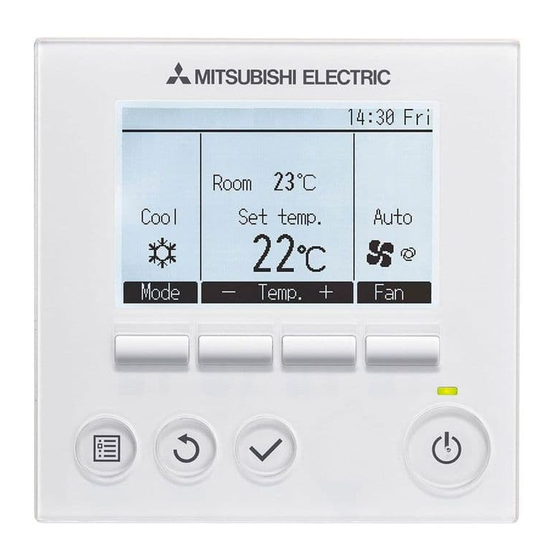
MA REMOTE CONTROLLER 1 . Product Features Feature Ideal remote controller in pur- Cool Set temp. Auto suit of easy operation, conveni- ence, and energy saving. Feature Mode Temp. EASY OPERATION Backlit LCD (Liquid Crystal Display) Full dot backlit LCD makes it easy to see and control units. Large, easy-to-see display Feature Full-dot LCD display with large characters for easy viewing Contrast also adjustable. - Page 3 MA REMOTE CONTROLLER Functions Basic Functions ▪ ON/OFF ▪ Operation mode switching ▪ Room temperature setting/display ▪ Fan speed setting ▪ Vane setting ▪ Louver setting ▪ Clock setting/display ▪ Filter information display Advanced Functions Display mode switching The main display can be displayed in two different modes: "Full" and "Basic". Error code, error unit, unit address, unit model, serial number, contact information (dealer's phone number) can be displayed.
-
Page 4: Safety Precautions
This controller is designed for exclusive use with the Building cloth. Management System by Mitsubishi Electric. The use of this controller for with other systems or for other purposes may To avoid damage to the controller, provide protection against cause malfunctions. -
Page 5: Names And Functions Of Controller Components
MA REMOTE CONTROLLER 3 . Names and functions of controller components Display The main display can be displayed in two different modes: "Full" and "Basic". The factory setting is "Full". To switch to the "Basic" mode, change the setting on the Main display setting. (Refer to D-51) <Full mode>... - Page 6 MA REMOTE CONTROLLER Controller interface The functions of the function buttons change depend- ing on the screen. Refer to the button function guide that appears at the bottom of the LCD for the functions they serve on a given screen. When the system is centrally controlled, the button function guide that corresponds to the locked button will not appear.
-
Page 7: Read Before Operating The Controller
MA REMOTE CONTROLLER 4 . Read before operating the controller 1. Menu structure Press the button. MENU Main menu Move the cursor to the desired item with the buttons, and press the button. SELECT Vane · Louver · Vent. (Lossnay) High power Timer On / Off timer... -
Page 8: Main Menu List
MA REMOTE CONTROLLER 2. Main menu list Setting and display items Setting details Vane · Louver · Vent. Use to set the vane angle. (Lossnay) • Select a desired vane setting from five different settings. Use to turn ON / OFF the louver. •... -
Page 9: Remote Controller Function
3. Remote controller function * The functions which can be used are restricted according to the model. : Supported : Unsupported PAR-33MAA Function Slim City multi Body Product size H × W × D (mm) 120 ×... -
Page 10: Icon Explanations
MA REMOTE CONTROLLER PAR-33MAA Function Slim City multi Maintenance Auto descending panel operation Clock Language selection Night setback Smooth maintenance Refrigerant leak check Support Contact information (Manual entry) Model name Serial No (Manual entry) 4. Icon explanations Controller operation The table below summarizes the square Timer icons used in this manual. -
Page 11: Controller Operation - Basic Operations
MA REMOTE CONTROLLER 5 . Controller operation - Basic operations 1. Power ON / OFF Button operation [ ON ] [ OFF ] Press the ON/OFF button. Press the ON/OFF button again. The ON / OFF lamp will light up in The ON / OFF lamp will come off, green, and the operation will start. -
Page 12: Operation Mode, Temperature, And Fan Speed Settings
MA REMOTE CONTROLLER 2. Operation mode, temperature, and fan speed settings Button operation [ Operation mode ] Press the F1 button to go through the operation modes in the order of "Cool, Dry, Fan, Auto, and Heat." Select the desired operation mode. Room Cool Set temp. - Page 13 MA REMOTE CONTROLLER [ Preset temperature ] <Cool, Dry, Heat, and Auto (single set point)> Press the F2 button to decrease the preset temperature, and press the F3 button to Room increase. Cool Set temp. Auto •Refer to the table on page D-11 for the settable temperature range for different operation modes.
- Page 14 MA REMOTE CONTROLLER Press the F1 or F2 button to move the cursor Set Temp. to the desired temperature setting (cooling or heating). Preset temperature Press the F3 button to decrease the selected for cooling temperature, and F4 to increase. Main display: Preset Cursor...
-
Page 15: Navigating Through The Main Menu
MA REMOTE CONTROLLER 3. Navigating through the Main menu Button operation [ Accessing the Main menu ] Press the button. Main Main menu Vane·Louver·Vent. (Lossnay) High power The Main menu will appear. Timer Weekly timer OU silent mode Main display: Cursor Page [ Item selection ]... - Page 16 MA REMOTE CONTROLLER [ Saving the settings ] Select the desired item, and press the button. OU silent mode Tue Wed Thu Fri Sat Sun The screen to set the selected item will appear. Start Stop Silent Setting display: [ Exiting the Main menu screen ] Press the button to exit the Main menu and return to the Main display.
-
Page 17: Vane · Louver · Vent. (Lossnay
MA REMOTE CONTROLLER 4. Vane · Louver · Vent. (Lossnay) Button operation [ Accessing the menu ] Select "Vane · Louver · Vent. (Lossnay)" from the Main menu (refer to D-15), Main Main menu and press the button. Vane·Louver·Vent. (Lossnay) High power Timer Weekly timer... -
Page 18: Vane · Louver · Vent. (Lossnay) ·······························································
MA REMOTE CONTROLLER [ Louver setting ] Press the F4 button to turn the louver swing ON and OFF. Vane Vent. Louver (Sample screen on City Multi) [ Vent. setting ] Press the F3 button to go through the ventilation setting options in the or- der of "Off,"... -
Page 19: Timer
MA REMOTE CONTROLLER 5. Timer Main 5.1. ON / OFF timer The unit automatically turns on or off at the preset time. (ex. Operation start time PM 2:30/ Operation stop time AM 12:50/ only one) Button operation [ 1 ] Select "Timer"... - Page 20 MA REMOTE CONTROLLER [ 4 ] Change the setting with the F3 or F4 button. Timer On/Off timer / Yes • On / Off timer: No (disable) / Yes (enable) Repeat No / • On: Operation start time (settable in 5-minute increments) Select: * Press and hold the button to rapidly advance the numbers.
-
Page 21: Auto-Off Timer
MA REMOTE CONTROLLER 5. Timer Main 5.2. Auto-OFF timer Button operation [ 1 ] Bring up the Timer setting screen. (Refer to D-19) Timer On/Off timer Select "Auto-Off", and press the button. Repeat Auto-Off Stop in --- min Setting display: Cursor The Auto-Off timer will not work in the following cases: when Auto-Off timer is disabled, during an error, during check (in the service... - Page 22 MA REMOTE CONTROLLER [ 4 ] Press the button to save the settings. Auto-Off timer Auto-Off Stop in Select: Cursor Time A confirmation screen will appear. Auto-Off timer Auto-Off Stop in Navigating through the screens Changes saved Main menu: • To go back to the Main menu ....button •...
-
Page 23: Filter Information
MA REMOTE CONTROLLER 6. Filter information will appear on the Main display in the Full mode when Room it is time to clean the filters. Wash, clean, or replace the filters when this sign ap- Cool Set temp. Auto pears. Refer to the indoor unit Instructions Manual for de- tails. - Page 24 MA REMOTE CONTROLLER When the is displayed on the Main display in the Full Room mode, the system is centrally controlled and the filter sign Cool Set temp. Auto cannot be reset. Mode Temp. If two or more indoor units are connected, filter cleaning timing for each unit may be different, depending on the filter type. The icon will appear when the filter on the main unit is due for cleaning.
-
Page 25: Error Information
MA REMOTE CONTROLLER 7. Error information When an error occurs, the following screen will appear. Check the error status, stop the operation, and consult your dealer. Button operation [ 1 ] Error code, error unit, refrigerant address, unit model name, and serial number Error information will appear. -
Page 26: High Power
MA REMOTE CONTROLLER Checking the error information While no errors are occurring, page 2/2 of the error information (refer to D-25) Main Main menu can be viewed by selecting "Error information" from the Main menu (refer to Restriction D-15). Energy saving Night setback Errors cannot be reset from this screen. -
Page 27: Controller Operation - Function Settings
MA REMOTE CONTROLLER 6 . Controller operation - Function settings Main 1. Weekly timer • ON / OFF and temperature setting can be scheduled for each day. • "Weekly timer" is not executed when the On / Off timer is enabled. Button operation [ 1 ] Select "Weekly timer"... - Page 28 MA REMOTE CONTROLLER [ 4 ] The weekly timer setting screen will appear and the current settings will be dis- Weekly timer played. Mon Tue Wed Thu Fri Sat Sun Up to eight operation patterns can be set for each day. Move the cursor to the desired day of the week with the F1 or F2 button, and press the F3 button to select it.
-
Page 29: Ou Silent Mode
MA REMOTE CONTROLLER Administrator Main 2. OU silent mode This function allows the user to set the time periods in which priority is given to quiet operation of outdoor units over temperature control. Set the start and stop times each day of the week for the quiet operation. Select the desired silent level from "Middle"... - Page 30 MA REMOTE CONTROLLER [ 4 ] The OU silent mode setting screen will appear. OU silent mode Mon Tue Wed Thu Fri Sat Sun To make or change the setting, move the cursor to the desired day of the Start Stop Silent week with the F1 or F2 button, and press the F3 button to select it.
-
Page 31: Energy Saving
MA REMOTE CONTROLLER 3. Energy saving Main 3.1. Automatic return to the preset temperature After the Auto return function is enabled, when the operation mode change or ON/OFF operation is performed from this re- mote controller, the set temperature automatically returns to the required temperature regardless of the set time. Button operation [ 1 ] Select "Energy saving"... - Page 32 MA REMOTE CONTROLLER [ 4 ] Change the settings with the F3 or F4 button. Auto return Auto return No / Cool: After • Auto return: No (disable) / Yes (enable) back to Heat: After • Cool: Timer setting range is 30 to 120 minutes in 10-minute increments. back to Temperature setting range is 19 to 30°C (67 to 87°F).
-
Page 33: Setting The Energy-Saving Operation Schedule
MA REMOTE CONTROLLER 3. Energy saving Main 3.2. Setting the energy-saving operation schedule Set the Energy-saving operation start time, end time and performance save value for one week. Button operation [ 1 ] Bring up the "Energy saving" screen. (refer to D-31) Energy saving Auto return Move the cursor to the "Schedule,"... - Page 34 MA REMOTE CONTROLLER [ 5 ] The pattern setting screen will appear. Energy saving Press the F1 button to move the cursor to the desired pattern number. Move the cursor to the desired item with the F2 button out of the start Select: Cursor Content...
- Page 35 MA REMOTE CONTROLLER 4. Night setback Main This control starts heating operation when the control object group is stopped and the room temperature drops below the pre- set lower limit temperature. Also, this control starts cooling operation when the control object group is stopped and the room temperature rises above the preset upper limit temperature.
- Page 36 MA REMOTE CONTROLLER will appear on the Main display in the Full mode when the Night setback function is enabled. Room Cool Set temp. Auto appears when the timer is disabled by the centralized control system. Mode Temp. The Night setback will not work in the following cases: when the unit is in operation, when the Night setback function is disabled, during an error, during check (in the service menu), during test run, during remote controller di-...
-
Page 37: Night Setback
MA REMOTE CONTROLLER 5. Restriction 5.1. Setting the temperature range restriction Use to restrict the preset temprature range. Button operation [ 1 ] Select "Restriction" from the Main menu (refer to D-15), and press the Main Main menu Restriction button. Energy saving Night setback Filter information... - Page 38 MA REMOTE CONTROLLER [ 4 ] Change the settings with the F3 or F4 button. Temp. range Temp. range No / Cool·Dry • Temp. range: No (unrestricted) or Yes (restricted) Heat Auto • Cool · Dry: Upper and lower limit temperature (1°C increments) •...
-
Page 39: Operation Lock Function
MA REMOTE CONTROLLER 5. Restriction 5.2. Operation lock function • To enable the operation lock function, set the item "Operation locked" to "Yes". • The On / Off operation, Operation mode setting, Preset temp, Setting and Vane Setting operations can all be restricted. Button operation [ 1 ] Bring up the Restriction setting screen. -
Page 40: Maintenance
MA REMOTE CONTROLLER 7 . Maintenance 1. Auto descending panel Main Button operation [ 1 ] Select "Maintenance" from the Main menu (refer to D-15), and press Maintenance menu button. Auto descending panel Manual vane angle Select "Auto descending panel" with the F1 or F2 button, and press Main menu: button. -
Page 41: Manual Vane Angle
MA REMOTE CONTROLLER 2. Manual vane angle Main Applies to the of Ceiling cassette type. Use to set the vane angle for each vane to a fixed position. Button operation [ 1 ] Select "Maintenance" from the Main menu (refer to D-15), and press Main Main menu button. - Page 42 MA REMOTE CONTROLLER [ 4 ] The current vane setting will appear. Manual vane angle Select the desired outlets from 1 through 4 with the F1 or F2 button. • Outlet: "1," "2," "3," "4," and "1, 2, 3, 4, (all outlets)" Select: Outlet Angle...
-
Page 43: D I-See Sensor Setting
MA REMOTE CONTROLLER 3. 3D i-see Sensor setting Main 3.1. 3D i-see Sensor setting Button operation [ 1 ] Select "Maintenance" from the Main menu (refer to D-15), and press Main Main menu button. Maintenance Initial setting Service Main display: Cursor Page [ 2 ]... -
Page 44: Air Distribution
MA REMOTE CONTROLLER 3.2. Air distribution Button operation [ 1 ] Select "Maintenance" from the Main menu (refer to D-15), and press 3D i-See sensor button. Air distribution Energy saving option Seasonal airflow Select "3D i-See sensor" with the F1 or F2 button, and press the but- Setting display: ton. - Page 45 MA REMOTE CONTROLLER [ 3 ] Select the menu with the F4 button. Air distribution Default → Area → Direct/Indirect → Default… Ref. address Unit No. Auto vane Direct/Indirect Direct/Indirect setting Default: The vanes move the same as during normal operation. Select: During cooling mode, all of the vanes move to the horizontal airflow direc- Cur.
-
Page 46: Energy Saving Option
MA REMOTE CONTROLLER 3.3. Energy saving option Button operation [ 1 ] Select "Maintenance" from the Main menu (refer to D-15), and press Energy saving option button. No occupancy energy save Room occupancy energy save No occupancy Auto-OFF Select "3D i-See sensor" with the F1 or F2 button, and press the but- Setting display: ton. - Page 47 MA REMOTE CONTROLLER [ 3 ] OFF: The function is disabled. Energy saving option Cooling only: The function is enabled only during cooling mode. No occupancy energy save Heating only: The function is enabled only during heating mode. Cooling/Heating Cooling/Heating: The function is enabled during both cooling mode and heating mode.
-
Page 48: Seasonal Airflow Function
MA REMOTE CONTROLLER 3.4. Seasonal airflow function Button operation [ 1 ] Select "Maintenance" from the Main menu (refer to D-15), and press Seasonal airflow button. Seasonal airflow Cooling/Heating Select "3D i-See sensor" with the F1 or F2 button, and press the but- Select: ton. -
Page 49: Initial Setting
MA REMOTE CONTROLLER 8 . Initial setting 1. Main / Sub When connecting two remote controllers, one of them needs to designated as a sub controller. Button operation [ 1 ] Select "Initial setting" from the Main menu (refer to D-15), and press Main Main menu button. -
Page 50: Clock
MA REMOTE CONTROLLER 2. Clock Button operation [ 1 ] Select "Initial setting" from the Main menu (refer to D-15), and press Main Main menu button. Maintenance Initial setting Service Main display: Clock setting is required before making the following settings. Cursor Page •... -
Page 51: Main Display
MA REMOTE CONTROLLER 3. Main display Button operation [ 1 ] Select "Initial setting" from the Main menu (refer to D-15), and press Initial setting menu button. Main/Sub Clock Main display Contrast Display details Move the cursor to the "Main display" with the F1 or F2 button, and Main menu: press the button. -
Page 52: Contrast
MA REMOTE CONTROLLER Main 4. Contrast Button operation [ 1 ] Select "Initial setting" from the Main menu (refer to D-15), and press Initial setting menu button. Main/Sub Clock Main display Contrast Display details Move the cursor to the "Contrast" with the F1 or F2 button, and press Main menu: button. - Page 53 MA REMOTE CONTROLLER 5. Display detail setting 5.1. Clock Button operation [ 1 ] Select "Initial setting" from the Main menu (refer to D-15), and press Initial setting menu button. Main/Sub Clock Main display Contrast Display details Move the cursor to the "Display details" with the F1 or F2 button, and Main menu: Cursor Page...
-
Page 54: Display Detail Setting
MA REMOTE CONTROLLER 5. Display detail setting 5.2. Temperature Unit, Room temp, Auto mode Button operation [ 1 ] Select "Initial setting" from the Main menu (refer to D-15), and press Display details button. Clock No 24h Temperature Room temp. / No Auto mode / No... -
Page 55: Auto Mode Setting
MA REMOTE CONTROLLER 6. Auto mode setting Whether or not to use the Auto (single set point) or Auto (dual set points) mode can be selected by using the F3 or F4 but- ton. Button operation [ 1 ] Select "Initial setting" from the Main menu (refer to D-15), and press Initial setting menu button. -
Page 56: Administrator Password Setting
MA REMOTE CONTROLLER 7. Administrator password setting The administrator password is required to make the settings for the following items. • Timer setting • Energy-save setting • Weekly timer setting • Restriction setting • Outdoor unit silent mode setting Button operation [ 1 ] Select "Initial setting"... - Page 57 MA REMOTE CONTROLLER 8. Language selection The desired language can be set. The language options are English, French, German, Spanish, Italian, Portuguese, Swedish, and Russian. Button operation [ 1 ] Select "Initial setting" from the Main menu (refer to D-15), and press Initial setting menu button.
- Page 58 MA REMOTE CONTROLLER Main 9. Daylight saving time The start/end time for daylight saving time can be set. The daylight saving time function will be activated based on the setting contents. • If a given system has a system controller, disable this setting to keep the correct time. •...
- Page 59 MA REMOTE CONTROLLER [ 2 ] Move the cursor to the following items with the F1 button to make the settings. Daylight saving time / Yes • DST Day / Week / Month Select "No" (disable) or "Yes" (enable) with the F2 button. The default setting Date(Start) Sun / 5th / Mar Start time...
-
Page 60: Service
MA REMOTE CONTROLLER 9 . Service 1. Service menu Maintenance password is required Button operation [ 1 ] Select "Service" from the Main menu (refer to D-15), and press the but- Main Main menu Maintenance ton. Initial setting Service *At the main display, the menu button and select "Service" to make the maintenance setting. -
Page 61: Test Run
MA REMOTE CONTROLLER 2. Test run Refer to the indoor unit Installation Manual for how to make the settings. Button operation [ 1 ] Select "Service" from the Main menu (refer to D-15), and press the but- Test run ton. Input maintenance info. -
Page 62: Drain Pump Test Run
MA REMOTE CONTROLLER 3. Drain pump test run It is possible to run just the drain pump without running the indoor unit’s fan. Carry this out after completing the indoor and outdoor electrical work. * Refer to the indoor unit’s installation manual, and confirm that the water is accurately drained, and that no water is leaking from the pipe connections. -
Page 63: Input Maintenance Info
MA REMOTE CONTROLLER 4. Input maintenance Info. Select "Input maintenance Info." from the Service menu to bring up the Maintenance information screen. Refer to the indoor unit Installation Manual for how to make the settings. Button operation [ 1 ] Select "Service"... - Page 64 MA REMOTE CONTROLLER [ 4 ] <For Mr.Slim> Model name input. Model infomation Add. PUHZ - RP VHA Select the unit to be registered with the F1 and F2 buttons. PLA - RP BA <For Mr.Slim> ■ Setting the "Registered unit" [OU] / [IU1] to [IU4] Select: Letter •...
- Page 65 MA REMOTE CONTROLLER Dealer information input [ 6 ] Select "Dealer information input" on the Maintenance information, and Dealer information press the button. Dealer The current settings will appear. Then press the button again. Input: Move the input cursor to the left and right with the buttons, Dealer information and select the letters with...
- Page 66 MA REMOTE CONTROLLER [ 8 ] Dealer information reset. Reset maintenance info. Model/Serial No. information Dealer information Select "Initialize maintenance info." on the Maintenance information, and press the button. Reset: Cursor Select "Dealer information" and press the button. Reset maintenance info. Model/Serial No.
-
Page 67: Function Setting
MA REMOTE CONTROLLER 5. Function Setting 5.1. Mr.Slim Button operation [ 1 ] Select "Service" from the Main menu (refer to D-15), and press the but- ton. Test run Input maintenance info. Function setting Check Self check Select "Function setting" with the F1 or F2 button, and press the button. - Page 68 MA REMOTE CONTROLLER [ 5 ] When the settings are completed, press the button to send the setting Function setting data from the remote controller to the indoor units. Ref. address When the transmission is successfully completed, the screen will return to the Sending data Function setting screen.
-
Page 69: City Multi
MA REMOTE CONTROLLER 5.2. City Multi Button operation [ 1 ] Select "Service" from the Main menu (refer to D-15), and press the but- ton. Test run Input maintenance info. Function setting Select "Function setting" with the F1 or F2 button, and press the button. -
Page 70: Lossnay Setting (City Multi
MA REMOTE CONTROLLER 6. LOSSNAY setting (City Multi) This setting is required only when the operation of City Multi units is interlocked with LOSSNAY units. This setting is not avail- able for the Mr. Slim units. Interlock settings can be made for the indoor unit to which the remote controller is connected. (They can also be confirmed or deleted.) note: •... - Page 71 MA REMOTE CONTROLLER [ 4 ] To make LOSSNAY interlock setting Lossnay IU address Enter the addresses of the indoor unit and the LOSSNAY unit to be inter- Lossnay address locked, with the F1 through F4 buttons, select "Set" in the "Function", Sending data and press the button to save the settings.
-
Page 72: Check
MA REMOTE CONTROLLER 7. Check 7.1. Error history Button operation [ 1 ] Select "Service" from the Main menu (refer to D-15), and press the but- Test run ton. Input maintenance info. Function setting Check Self check Select "Check" with the F1 or F2 button, and press the button. -
Page 73: Refrigerant Leak Check
MA REMOTE CONTROLLER Main 7. Check 7.2. Refrigerant leak check Refrigerant leakage is detected after a long time. To enable this function, the refrigerant volume must be saved (initial learning) after installation. Always operate this function in the following manner after installation. •... -
Page 74: Smooth Maintenance
MA REMOTE CONTROLLER Main 7. Check 7.3. Smooth maintenance Maintenance data, such as the indoor/outdoor unit’s heat exchanger temperature and compressor operation current can be displayed with “Smooth maintenance”. * This cannot be executed during test operation. * Depending on the combination with the outdoor unit, this may not be supported by some models. Button operation [ 1 ] Select "Service"... - Page 75 MA REMOTE CONTROLLER Main 7. Check 7.4. Request code Details on the operation data including each thermistor temperature and error history can be confirmed with the remote con- troller. Button operation [ 1 ] Select "Service" from the Main menu (refer to D-15), and press the but- Check menu ton.
-
Page 76: Request Code
MA REMOTE CONTROLLER <Request Cord list> * The Request code 150 – 152 data is the information for the indoor unit to which the remote controller is connected. Request Request content Description (Display range) Unit Remarks code Operation state Refer to "Operation mode" –... -
Page 77: Self Check
MA REMOTE CONTROLLER 8. Self check Button operation [ 1 ] Select "Service" from the Main menu (refer to D-15), and press the but- Test run ton. Input maintenance info. Function setting Check Select "Self check" with the F1 or F2 button, and press the button. -
Page 78: Maintenance Password
MA REMOTE CONTROLLER 9. Maintenance password Button operation [ 1 ] Select "Service" from the Main menu (refer to D-15), and press the but- Maintenance password ton. Remote controller check Select "maintenance password" with the F1 or F2 button, and press button. -
Page 79: Remote Controller Check
MA REMOTE CONTROLLER 10. Remote controller check If operations cannot be completed with the remote controller, diagnose the remote controller with this function. Button operation [ 1 ] Select "Service" from the Main menu (refer to D-15), and press the but- Maintenance password ton. -
Page 80: Specifications ∙ Outline Dimensions
MA REMOTE CONTROLLER . Specifications ∙ Outline Dimensions 1. Specifications <Specifications> Product size 120(W) × 120(H) × 19(D) mm (4 3/4 × 4 3/4 × 3/4 [in] ( not including the protruding part ) Net weight 0.25kg (9/16lb.) Rated power supply voltage 12V DC (supplied from indoor units) Power consumption 0.3W Usage environment... - Page 81 MA Remote Controller Simple MA remote controller [PAC-YT52CRA] 1. Product Feature ··························································································································· D-82 2. Functions ··································································································································· D-83 1. Operations/Display ····················································································································· D-83 2. Restriction settings ··················································································································· D-83 3. Miscellaneous ·························································································································· D-83 3. Names and functions of controller components ·············································································· D-84 1. Controller interface ····················································································································· D-84 2.
-
Page 82: Product Feature
MA REMOTE CONTROLLER 1 . Product Feature New Design • Backlit LCD Backlight for operation in dark place • LCD size up 20 x 31(mm) [0.78 x 1.22(in)] →22 x 37(mm) [0.9 x 1.5(in)] • Flat back Install without hole on wall Slim and flat type : Thickness is less than 14.5mm [0.6(in)] •... -
Page 83: Functions
MA REMOTE CONTROLLER 2 . Functions 1. Operations/Display Setting Display Description Item Operation mode Select from COOL, DRYING, FAN, AUTO, and HEAT. switching Sets a room temperature. * The preset temperature range varies depending on the indoor unit model to be connected. Room temp. -
Page 84: Names And Functions Of Controller Components
MA REMOTE CONTROLLER 3 . Names and functions of controller components 1.Controller interface ON/OFF lamp The lamp will light up in green when turned on, and blink during startup and when an error occurs. Backlit LCD button Pressing this button starts and stops the operation. -
Page 85: Basic Operations
MA REMOTE CONTROLLER 4 . Basic operations 1.Operation mode Pressing the button will change the operation mode in the following order. COOL DRYING AUTO HEAT VENTI. *1: Not all functions are available on all models of indoor units. Functions that are not available will not appear on the display. -
Page 86: Preset Temperature
MA REMOTE CONTROLLER 2.Preset temperature In COOL, DRYING, HEAT, and AUTO (single set point) modes Pressing the button increases the preset temperature. Pressing the button decreases the preset temperature. In AUTO (dual set point) mode Cooling preset temperature Current preset temperature (cooling/heating) appears. When the button is pressed, the preset temperature (cooling/heating) display blinks. -
Page 87: Fan Speed
MA REMOTE CONTROLLER 3.Fan speed Pressing the button will change the fan speed in the following order. AUTO * The settable fan speed varies depending on the indoor unit model to be connected. * If the unit has no fan setting function, the fan speed cannot be set. In this case, the fan icon blinks when the button is pressed. -
Page 88: Controller Operation-Function Settings
MA REMOTE CONTROLLER 5 . Controller operation-Function settings 1.Temperature range restriction The preset temperature range for each operation mode can be restricted. The air conditioning unit stops. (1 ) (6 ) (Press the button for three seconds or longer.) (Press the button for three (2 ) seconds or longer.) B. -
Page 89: Operation Lock Setting
MA REMOTE CONTROLLER Press the button to set upper/lower limit value. • Pressing the buttons simultaneously can bring up the previous temperature range of COOL/DRYING, HEAT, and AUTO modes. • The temperature can be adjusted within the preset temperature range of the indoor unit. Refer to the Indoor unit Instruction Book for details. -
Page 90: Specifications
MA REMOTE CONTROLLER Press the button to stop the air conditioning unit. Press the buttons simultaneously for three seconds or longer to bring up the Mode skip settings display. (The current setting will appear.) Press the button to select ON or OFF. ON: AUTO mode can be selected by pressing the button during operation. - Page 91 Wireless Remote Controller [PAR-SL100A-E] 1. Safety Precautions ······················································································································· D-92 2. Names and functions of controller components ·············································································· D-93 3. Before Operation ························································································································· D-94 3.1. Replacing the batteries and how to set the current time ····························································· D-94 3.2. Initial setting ························································································································· D-95 4.
-
Page 92: Safety Precautions
WIRELESS REMOTE CONTROLLER 1 . Safety Precautions • Be sure to read these Safety precautions thoroughly and install the remote controller correctly. • The following two symbols are used to denote dangers that may be caused by incorrect use. They are classified according to the degree of danger. -
Page 93: Names And Functions Of Controller Components
WIRELESS REMOTE CONTROLLER 2 . Names and functions of controller components Controller interface Transmission area Remote controller display Set Temperature buttons OFF/ON button Mode button (Changes operation mode) Fan Speed button (Changes fan speed) Airflow button (Changes up/ i-see button* down airflow direction) Timer ON button Menu button... -
Page 94: Before Operation
WIRELESS REMOTE CONTROLLER 3 . Before Operation 3.1. Replacing the batteries and how to set the current time Battery installation/replacement 1. Remove the top cover, insert two LR6 AA batteries, 2. Press the Reset button. and then install the top cover. Top cover Press the Reset button with an object that has a narrow end. -
Page 95: Initial Setting
WIRELESS REMOTE CONTROLLER 3.2. Initial setting The following settings can be made in the initial setting mode. Item Setting Fig. 3-1, 3-2 Temperature unit ºC/ºF Time display 12-hour format/24-hour format AUTO mode Single set point/Dual set point Pair No. 0–3 Backlight On/Off 1) Switching to the initial setting mode... - Page 96 WIRELESS REMOTE CONTROLLER 8) Operation mode setting 1. Press the button 1 to stop the air conditioner. 2. Press the button 8 in 5 seconds. Model setting screen will be displayed. 3. Press the button 2. Operation mode A blinks. (Fig. 3-3) 4.
-
Page 97: Operation
WIRELESS REMOTE CONTROLLER $ . Operation 4.1. Switching the unit on/off 1. Press the button 1. • The remote controller display turns on. 2. Press the button 2. • Each time the button is pressed, the setting changes. Auto Heat Cool * If the automatic operation is selected, cooling operation starts if the room temperature is higher than the set temperature and heating operation... -
Page 98: Selecting A Fan Speed (Fan
WIRELESS REMOTE CONTROLLER 4.3. Selecting a fan speed (FAN) Press the button 4. • Each time the button is pressed, the setting changes. Auto • The available fan speeds depend on the model of the indoor unit. Note: In the following cases, the actual fan speed generated by the unit may be different from the speed shown on the remote controller display. •... -
Page 99: Using The On/Off Timer
WIRELESS REMOTE CONTROLLER 4.5. Using the on/off timer • When setting the timer operation, point the transmission area of the wireless remote controller towards the receiver on the indoor unit and confirm that the indoor unit beeps when it receives signals from the On time remote controller. -
Page 100: Using The Weekly Timer
WIRELESS REMOTE CONTROLLER 4.6. Using the weekly timer • This function cannot be operated depending on the model of the indoor unit. • The weekly timer can be set to 4 operation patterns for each day of the week. • The settings include the on and off times and the set temperature. •... -
Page 101: I-See Sensor
WIRELESS REMOTE CONTROLLER 4.7. i-see Sensor • This function cannot be operated depending on the model of the indoor unit. 1 Each time is pressed during operation, the setting changes in the following order: OFF → Direct → Indirect. Display Setting Direct Indirect... -
Page 102: Special Operation
WIRELESS REMOTE CONTROLLER 5 . Special Operation Some functions cannot be operated depending on the air conditioner. Confirm whether the air conditioner supports each function, and then op- erate the air conditioner. <Switching to the special operation mode> 1. Press the button 1 to stop the air conditioner. -
Page 103: Operating The Ascending/Descending Panel
WIRELESS REMOTE CONTROLLER 5.2. Operating the ascending/descending panel 1. In the Function setting screen, press the button 4 and select function No. “3”. 2 Press the button 3. • The ascending/descending mark G blinks. (Fig. 5-2) 3. Press the button 4 or the button 5.
Need help?
Do you have a question about the PAR-33MAA and is the answer not in the manual?
Questions and answers