Siemens Simatic S7-200 System Manual
Programmable controller
Hide thumbs
Also See for Simatic S7-200:
- System manual (607 pages) ,
- Getting started (65 pages) ,
- Manual (55 pages)
Table of Contents
Advertisement
Quick Links
SIMATIC
S7-200 Programmable Controller
System Manual
This manual has the order number:
6ES7298-8FA01-8BH0
Preface, Contents
Introducing the
S7-200 Micro PLC
Installing an S7-200
Micro PLC
Installing and Using the
STEP 7-Micro/WIN Software
Getting Started with a
Sample Program
Additional Features of
STEP 7-Micro/WIN
Basic Concepts for
Programming an S7-200
CPU
CPU Memory: Data Types
and Addressing Modes
Input/Output Control
Network Communications
and the S7-200 CPU
Instruction Set
Appendix
S7-200 Data Sheets
Power Calculation Table
Error Codes
Special Memory (SM) Bits
How STEP 7-Micro/WIN
Works with Other STEP 7
Programming Products
Execution Times for STL
Instructions
S7-200 Order Numbers
S7-200 Troubleshooting
Guide
Index
1
2
3
4
5
6
7
8
9
10
A
B
C
D
E
F
G
H
Advertisement
Table of Contents

Related Manuals for Siemens Simatic S7-200


Summary of Contents for Siemens Simatic S7-200
- Page 1 Preface, Contents Introducing the S7-200 Micro PLC Installing an S7-200 Micro PLC Installing and Using the STEP 7-Micro/WIN Software Getting Started with a Sample Program SIMATIC Additional Features of STEP 7-Micro/WIN Basic Concepts for S7-200 Programmable Controller Programming an S7-200 CPU Memory: Data Types and Addressing Modes System Manual...
- Page 2 Trademarks SIMATIC , SIMATIC NET and SIMATIC HMI are registered trademarks of Siemens AG. STEP 7 and S7 are trademarks of Siemens AG. Microsoft , Windows , Windows 95, and Windows NT are registered trademarks of Microsoft Corporation.
-
Page 3: S7-200 Micro Plc
– STEP 7-Micro/WIN 32 for the 32-bit Windows 95 and Windows NT Agency Approvals The SIMATIC S7-200 series meets the standards and regulations of the following agencies: European Community (CE) Low Voltage Directive 73/23/EEC European Community (CE) EMC Directive 89/336/EEC Underwriters Laboratories, Inc.: UL 508 Listed (Industrial Control Equipment) - Page 4 For assistance in answering technical questions, for training on this product, or for ordering, contact your Siemens distributor or sales office. For Internet information about Siemens products and services, technical support, or FAQs (frequently asked questions) and application tips, use this Internet address: http://www.ad.siemens.de...
-
Page 5: Table Of Contents
Contents Introducing the S7-200 Micro PLC ........Comparing the Features of the S7-200 Micro PLCs . - Page 6 Contents Using Find/Replace ........... . . 5-19 Documenting Your Program .
- Page 7 Contents 10.5 Timer, Counter, High-Speed Counter, High-Speed Output, Clock, and Pulse Instructions ........... 10-13 10.6 Math and PID Loop Control Instructions...
- Page 8 Contents A.26 Expansion Module EM223 Digital Combination 4 x 24 VDC Input/4 x 24 VDC Output ........A-48 A.27 Expansion Module EM223 Digital Combination...
-
Page 9: Introducing The S7-200 Micro Plc
Introducing the S7-200 Micro PLC The S7-200 series is a line of micro-programmable logic controllers (Micro PLCs) that can control a variety of automation applications. Figure 1-1 shows an S7-200 Micro PLC. The compact design, expandability, low cost, and powerful instruction set of the S7-200 Micro PLC make a perfect solution for controlling small applications. -
Page 10: Comparing The Features Of The S7-200 Micro Plcs
Introducing the S7-200 Micro PLC Comparing the Features of the S7-200 Micro PLCs Equipment Requirements Figure 1-2 shows the basic S7-200 Micro PLC system, which includes an S7-200 CPU module, a personal computer, STEP 7-Micro/WIN programming software, and a communications cable. In order to use a personal computer (PC), you must have one of the following sets of equipment: A PC/PPI cable... - Page 11 Introducing the S7-200 Micro PLC Table 1-1 Summary of the S7-200 CPUs Feature CPU 212 CPU 214 CPU 215 CPU 216 Physical Size of Unit 160 mm x 80 mm 197 mm x 80 mm 218 mm x 80 mm 218 mm x 80 mm x 62 mm x 62 mm...
-
Page 12: Major Components Of The S7-200 Micro Plc
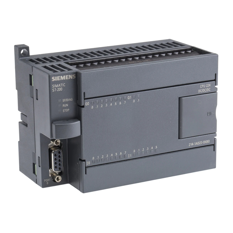
Introducing the S7-200 Micro PLC Major Components of the S7-200 Micro PLC An S7-200 Micro PLC consists of an S7-200 CPU module alone or with a variety of optional expansion modules. S7-200 CPU Module The S7-200 CPU module combines a central processing unit (CPU), power supply, and discrete I/O points into a compact, stand-alone device. - Page 13 Introducing the S7-200 Micro PLC I0.0 Q0.0 I0.1 Q0.1 Q0.2 STOP I0.2 Q0.3 I0.3 I0.4 Q0.4 Q0.5 I0.5 I0.6 SIMATIC I0.7 S7-200 Figure 1-3 S7-212 CPU Module I0.0 I1.0 Q0.0 Q1.0 I0.1 I1.1 Q0.1 Q1.1 I0.2 I1.2 Q0.2 STOP Q0.3 I0.3 I1.3 Q0.4...
- Page 14 Introducing the S7-200 Micro PLC Expansion Modules The S7-200 CPU module provides a certain number of local I/O. Adding an expansion module provides additional input or output points. As shown in Figure 1-6, the expansion module comes with a bus connector for connecting to the base unit. S7-200 CPU Module Expansion Module I0.0...
-
Page 15: Installing An S7-200 Micro Plc
Installing an S7-200 Micro PLC The installation of the S7-200 family is designed to be easy. You can use the mounting holes to attach the modules to a panel, or you can use the built-in clips to mount the modules onto a standard (DIN) rail. -
Page 16: Panel Layout Considerations
Installing an S7-200 Micro PLC Panel Layout Considerations Installation Configuration You can install an S7-200 either on a panel or on a standard rail. You can mount the S7-200 either horizontally or vertically. An I/O expansion cable is also available to add flexibility to your mounting configuration. - Page 17 Installing an S7-200 Micro PLC Standard Rail Requirements The S7-200 CPU and expansion modules can be installed on a standard (DIN) rail (DIN EN 50 022). Figure 2-3 shows the dimensions for this rail. 1.0 mm 35 mm (0.039 in.) (1.38 in.) 7.5 mm (0.29 in.)
- Page 18 Installing an S7-200 Micro PLC 217.3 mm 26.7 mm (8.56 in.) (1.05 in.) 184.3 mm 6.4 mm (7.26 in.) (0.25 in.) S7-215 or 80 mm S7-216 67.3 mm (3.15 in.) (2.65 in.) Mounting holes (M4 or no. 8) Figure 2-6 Mounting Dimensions for an S7-215 or S7-216 CPU Module 90 mm (3.54 in.)
-
Page 19: Installing And Removing An S7-200 Micro Plc
Installing an S7-200 Micro PLC Installing and Removing an S7-200 Micro PLC Mounting an S7-200 Micro PLC on a Panel Warning Attempts to install or remove S7-200 modules or related equipment when they are powered up could cause electric shock. Failure to disable all power to the S7-200 modules and related equipment during installation or removal procedures may result in death or serious personal injury, and/or damage to equipment. - Page 20 Installing an S7-200 Micro PLC Installing an S7-200 Micro PLC onto a Standard Rail Warning Attempts to install or remove S7-200 modules or related equipment when they are powered up could cause electric shock. Failure to disable all power to the S7-200 modules and related equipment during installation or removal procedures may result in death or serious personal injury, and/or damage to equipment.
- Page 21 Installing an S7-200 Micro PLC Removing the S7-200 Modules Warning Attempts to install or remove S7-200 modules or related equipment when they are powered up could cause electric shock. Failure to disable all power to the S7-200 modules and related equipment during installation or removal procedures may result in death or serious personal injury, and/or damage to equipment.
-
Page 22: Installing The Field Wiring
Installing an S7-200 Micro PLC Installing the Field Wiring Warning Attempts to install or remove S7-200 modules or related equipment when they are powered up could cause electric shock. Failure to disable all power to the S7-200 modules and related equipment during installation or removal procedures may result in death or serious personal injury, and/or damage to equipment. - Page 23 Installing an S7-200 Micro PLC Grounding and Circuit Reference Point Guidelines for Using Isolated Circuits The following items are grounding and circuit guidelines for using isolated circuits: You should identify the reference point (0 voltage reference) for each circuit in the installation, and the points at which circuits with possible different references can connect together.
- Page 24 Installing an S7-200 Micro PLC Using the Optional Field Wiring Connector The optional field wiring fan-out connector (Figure 2-11) allows for field wiring connections to remain fixed when you remove and re-install the S7-200. Refer to Appendix G for the order number.
- Page 25 Installing an S7-200 Micro PLC Guidelines for DC Installation The following items are general wiring guidelines for isolated DC installations. Refer to Figure 2-13. Provide a single disconnect switch (1) that removes power from the CPU, all input circuits, and all output (load) circuits. Provide overcurrent devices to protect the CPU power supply (2), the output points (3), and the input points (4).
- Page 26 Installing an S7-200 Micro PLC Guidelines for North American Installation The following items are general wiring guidelines for installations in North America where multiple AC voltages are present. Refer to Figure 2-14 as you read these guidelines. Provide a single disconnect switch (1) that removes power from the CPU, all input circuits, and all output (load) circuits.
-
Page 27: Using Suppression Circuits
Installing an S7-200 Micro PLC Using Suppression Circuits General Guidelines Equip inductive loads with suppression circuits that limit voltage rise on loss of power. Use the following guidelines to design adequate suppression. The effectiveness of a given design depends on the application, and you must verify it for a particular use. Be sure all components are rated for use in the application. - Page 28 Installing an S7-200 Micro PLC Protecting Relays That Control DC Power Resistor/capacitor networks, as shown in Figure 2-17, can be used for low voltage (30 V) DC relay applications. Connect the network across the load. where minimum R = 12 Ω +VDC Inductor where K is 0.5 µF/A to 1 µF/A...
-
Page 29: Power Considerations
Installing an S7-200 Micro PLC Power Considerations The S7-200 base units have an internal power supply that provides power for the base unit, the expansion modules, and other 24 VDC user power requirements. Use the following information as a guide for determining how much power (or current) the base unit can provide for your configuration. - Page 30 Installing an S7-200 Micro PLC Calculating a Sample Power Requirement Table 2-1 shows a sample calculation of the power requirements for an S7-200 Micro PLC that includes the following modules: CPU 214 DC/DC/DC Three EM 221 Digital Input 8 x DC 24 V expansion modules Two EM 222 Digital Output 8 x Relay expansion modules The CPU in this example provides sufficient 5 VDC current for the expansion modules;...
-
Page 31: Installing And Using The Step 7-Micro/Win Software
Recommended: a personal computer (PC) with an 80586 or greater processor and 16 Mbytes of RAM, or a Siemens programming device (such as a PG 740); minimum computer requirement: 80486 processor with 8 Mbytes One of the following sets of equipment: –... -
Page 32: Installing The Step 7-Micro/Win Software
Installing and Using the STEP 7-Micro/WIN Software Installing the STEP 7-Micro/WIN Software Pre-Installation Instructions Before running the setup procedure, do the following: If a previous version of STEP 7-Micro/WIN is installed, back up all STEP 7-Micro/WIN projects to diskette. Make sure all applications are closed, including the Microsoft Office toolbar. Installation may require that you restart your computer. - Page 33 Installing and Using the STEP 7-Micro/WIN Software Install/Remove Modules Selection: Installed: CPU5411 MPI-ISA Card CPU5511 (Plug & Play) PC/PPI cable Install --> CPU5611 (Plug & Play) MPI-ISA on board <-- Remove PC Adapter (PC/MPI-Cable) This button appears if you are using a Resources...
-
Page 34: Using Step 7-Micro/Win To Set Up The Communications Hardware
Installing and Using the STEP 7-Micro/WIN Software Using STEP 7-Micro/WIN to Set Up the Communications Hardware General Information for Installing or Removing the Communications Hardware If you are using Windows 95 or Windows NT 4.0, the Install/Remove Modules dialog box appears automatically at the end of your software installation. - Page 35 Installing and Using the STEP 7-Micro/WIN Software Note STEP 7-Micro/WIN 16 does not support the multi-master parameter set under the Windows 95 or Windows NT 4.0 operating system. The following hardware configurations are possible: CPU 212, CPU 214, CPU 216, CPU 215 (port 0) –...
- Page 36 Installing and Using the STEP 7-Micro/WIN Software Special Hardware Installation Information for Windows NT Users Installing hardware modules under the Windows NT operating system is slightly different from installing hardware modules under Windows 95. Although the hardware modules are the same for either operating system, installation under Windows NT requires more knowledge of the hardware that you want to install.
-
Page 37: Establishing Communication With The S7-200 Cpu
Installing and Using the STEP 7-Micro/WIN Software Establishing Communication with the S7-200 CPU You can arrange the S7-200 CPUs in a variety of configurations to support network communications. You can install the STEP 7-Micro/WIN software on a personal computer (PC) that has a Windows 3.1x, Windows 95, or Windows NT operating system, or you can install it on a SIMATIC programming device (such as a PG 740). - Page 38 Installing and Using the STEP 7-Micro/WIN Software Figure 3-4 shows a configuration with a personal computer connected to several S7-200 CPU modules. STEP 7-Micro/WIN is designed to communicate with one S7-200 CPU at a time; however, you can access any CPU on the network. The CPU modules in Figure 3-4 could be either slave or master devices.
- Page 39 Installing and Using the STEP 7-Micro/WIN Software Master devices TD 200 OP15 CPU 214 MPI or CP card MPI cable (RS-485) CPU 212 CPU 214 CPU 212 CPU 214 Slave devices Figure 3-5 Example of an MPI or CP Card with Master and Slave Devices From What Point Do I Set Up Communications? Depending on the operating system that you are using, you can set up communications from any of the following points:...
- Page 40 Installing and Using the STEP 7-Micro/WIN Software Setting Up Communications within STEP 7-Micro/WIN Within STEP 7-Micro/WIN there is a Communications dialog box that you can use to configure your communications setup. See Figure 3-6. You can use one of the following ways to find this dialog box: Select the menu command Setup Communications..
- Page 41 Installing and Using the STEP 7-Micro/WIN Software STEP 7-Micro/WIN Project View CPU Setup Help Setup Setting the PG/PC Interface Access Path Access Point of Application: Micro/WIN (Standard for Micro/WIN) Module Parameter Set Used: Properties... MPI-ISA Card(PPI) <None> MPI-ISA Card(MPI) MPI-ISA Card(PPI) Copy...
- Page 42 Installing and Using the STEP 7-Micro/WIN Software Setting Up Communications during Installation Under the Windows 95 or Windows NT 4.0 operating system, at the end of the STEP 7-Micro/WIN installation, the Communications dialog box appears automatically. You can set up your configuration at that time, or later. Selecting the Correct Module Parameter Set and Setting It Up When you have reached the Setting the PG/PC Interface dialog box (see Figure 3-7), you must select “Micro/WIN”...
- Page 43 Installing and Using the STEP 7-Micro/WIN Software From the Setting the PG/PC Interface dialog box, if you are using the PC/PPI cable and you click the “Properties...” button, the properties sheet appears for PC/PPI cable (PPI). See Figure 3-9. Follow these steps: In the PPI Network tab, select a number in the Local Station Address box.
- Page 44 Installing and Using the STEP 7-Micro/WIN Software Click the Local Connection tab. See Figure 3-10. In the Local Connection tab, select the COM port to which your PC/PPI cable is connected. If you are using a modem, select the COM port to which the modem is connected and select the Use Modem check box.
- Page 45 Installing and Using the STEP 7-Micro/WIN Software From the Setting the PG/PC Interface dialog box, if you are using any of the MPI or CP cards listed above along with the PPI protocol, and you click the “Properties...” button, the properties sheet appears for XXX Card(PPI), where “XXX”...
- Page 46 Installing and Using the STEP 7-Micro/WIN Software Setting Up the MPI Card (MPI) Parameters This section explains how to set up the MPI parameters for the following operating systems and hardware: Windows 3.1: MPI-ISA card (including those found in SIMATIC programming devices) Windows 95 or Windows NT 4.0: –...
- Page 47 Installing and Using the STEP 7-Micro/WIN Software Follow these steps: In the MPI Network tab, select a number in the Local Station Address box. This number indicates where you want STEP 7-Micro/WIN to reside on the programmable controller network. Make sure that the Not the Only Master Active check box is cleared, regardless of the number of masters you have on your network.
- Page 48 Installing and Using the STEP 7-Micro/WIN Software Troubleshooting the MPI Communications Setup for Windows NT 4.0 Setting up the MPI card correctly under Windows NT 4.0 is somewhat difficult. If you have problems with your setup (assuming that you have the MPI card installed in the communications setup screens), follow these steps: Make sure you have a working MPI card.
- Page 49 Installing and Using the STEP 7-Micro/WIN Software Connecting a CPU 215 as a Remote I/O Module You can connect the CPU 215 to a PROFIBUS network, where it can function as a remote I/O module owned by an S7-300 or S7-400 programmable logic controller or by another PROFIBUS master.
- Page 50 A PC/PPI cable to connect the null modem adapter to either of the following ports: – The communications port of the S7-200 CPU (see Figure 3-14) – A Siemens programming port connector on a PROFIBUS network (see Figure 9-3) RS-232...
- Page 51 Installing and Using the STEP 7-Micro/WIN Software Null Modem Adapter 25-Pin to 9-Pin Adapter Modem PC/PPI cable 25-pin 25-pin 25-pin 9-pin Figure 3-15 Pin Assignments for a Null Modem Adapter Setting Up the Communications Parameters When Using Modems To set up communications parameters between your programming device or PC and the CPU when using modems, you must use the module parameter set for the PC/PPI cable.
- Page 52 Installing and Using the STEP 7-Micro/WIN Software Click the “Configure Modems...” button. The Configure Modems dialog box appears. (You can also access the “Configure Modems...” button by selecting the menu command Setup Connect Modem..The button appears in the Connect dialog box.) The General Information tab of the Configure Modems dialog box provides the 11-bit data string requirements for the modems and lists the hardware components that you need.
- Page 53 Installing and Using the STEP 7-Micro/WIN Software 13. Click the Remote Modem Configuration tab. See Figure 3-17. 14. In the Remote Modem Configuration tab, in the Selected Modem list box, choose Multi Tech MultiModemZDX MT1932ZDX. 15. Click the “Program Modem” button. This action transfers the parameters into a memory chip in the remote modem.
- Page 54 Installing and Using the STEP 7-Micro/WIN Software 18. Disconnect your remote modem from your local machine (your programming device or PC). 19. Connect the remote modem to your S7-200 programmable controller. 20. Connect your local modem to your programming device or PC. 21.
-
Page 55: Configuring The Preferences For Step 7-Micro/Win
Installing and Using the STEP 7-Micro/WIN Software Configuring the Preferences for STEP 7-Micro/WIN Before creating a new project, specify the preferences for your programming environment. To select your preferences, follow these steps: Select the menu command Setup Preferences... as shown in Figure 3-19. Select your programming preferences in the dialog box that appears. -
Page 56: Creating And Saving A Project
Installing and Using the STEP 7-Micro/WIN Software Creating and Saving a Project Before you create a program, you must create or open a project. When you create a new project, STEP 7-Micro/WIN opens the following editors: Ladder Editor or Statement List Editor (depending on your selected preference) Data Block Editor Status Chart Symbol Table... -
Page 57: Creating A Program
Installing and Using the STEP 7-Micro/WIN Software Creating a Program STEP 7-Micro/WIN allows you to create the user program (OB1) with either the Ladder Editor or the Statement List Editor. Entering Your Program in Ladder Logic The Ladder Editor window allows you to write a program using graphical symbols (see Figure 3-21). - Page 58 Installing and Using the STEP 7-Micro/WIN Software Project Edit View CPU Debug Tools Setup Window Help Ladder Editor - c:\microwin\project1.ob1 Contacts Normally Open Network 1 NETWORK TITLE (single line) I0.0 Double click here to access the network title and comment editor. Select the instruction from the drop down list or the Instruction Toolbar, and...
- Page 59 Installing and Using the STEP 7-Micro/WIN Software Entering Your Program in Statement List The Statement List (STL) Editor is a free-form text editor which allows a certain degree of flexibility in the way you choose to enter program instructions. Figure 3-22 shows an example of a statement list program.
- Page 60 Installing and Using the STEP 7-Micro/WIN Software Downloading Your Program After completing your program, you can download the project to the CPU. To download your program, select the menu command Project Download... or click the Download button in the main window. The Download dialog box that appears allows you to specify the project components that you want to download, as shown in Figure 3-23.
- Page 61 Installing and Using the STEP 7-Micro/WIN Software Viewing a Program in Ladder Logic or Statement List You can view a program in either ladder or STL by selecting the menu command View or View Ladder, as shown in Figure 3-24. When you change the view from STL to ladder and back again to STL, you may notice changes in the presentation of the STL program, such as: Instructions and addresses are changed from lower case to upper case.
-
Page 62: Creating A Data Block
Installing and Using the STEP 7-Micro/WIN Software Creating a Data Block You can use the Data Block Editor to pre-define or initialize variables to be used in your program. Usage of the data block is optional. The Data Block Editor appears by default as a minimized window icon at the bottom of the main window (if selected in Setup Preferences... - Page 63 Real (floating point): use a period (“.”) and not a comma (“,”) 10.57 Text (ASCII): string text, contained within apostrophes ’Siemens’ (Note: “$” is a special character for designating that the following character is an ’That$’s it’ apostrophe or a dollar sign within a string.) ’Only $$25’...
-
Page 64: Using The Status Chart
Installing and Using the STEP 7-Micro/WIN Software Using the Status Chart You can use the Status Chart to read, write, or force variables in your program. The Status Chart editor appears by default as a minimized window icon at the bottom of the main window (if selected in Setup Preferences... - Page 65 Installing and Using the STEP 7-Micro/WIN Software Forcing Variables Using the Status Chart To force a variable in the Status Chart to a specific value, follow these steps: For a cell in the Address column, enter the address or symbol name of the variable that you want to force.
-
Page 66: Using Symbolic Addressing
Installing and Using the STEP 7-Micro/WIN Software Using Symbolic Addressing The Symbol Table allows you to give symbolic names to inputs, outputs, and internal memory locations. See Figure 3-27. You can use the symbols that you have assigned to these addresses in the Ladder Editor, STL Editor, and Status Chart of STEP 7-Micro/WIN. The Data Block Editor does not support the use of symbolic names. - Page 67 Installing and Using the STEP 7-Micro/WIN Software Editing Functions within the Symbol Table The Symbol Table provides the following editing functions: Edit Cut / Copy / Paste within a cell or from one cell to another. Edit Cut / Copy / Paste one or several adjacent rows. Edit Insert Row above the row containing the cursor.
- Page 68 Installing and Using the STEP 7-Micro/WIN Software S7-200 Programmable Controller System Manual 3-38 C79000-G7076-C230-02...
-
Page 69: Getting Started With A Sample Program
Getting Started with a Sample Program The examples and descriptions in this manual support Version 2.1 of STEP 7-Micro/WIN programming software. Previous versions of the programming software may operate differently. This chapter describes how to use the STEP 7-Micro/WIN software to perform the following tasks: Entering a sample program for a mixing tank with two supply pumps Creating a Symbol Table, Status Chart, and Data Block... -
Page 70: Creating A Program For A Sample Application
Getting Started with a Sample Program Creating a Program for a Sample Application System Requirements for the Sample Program After you create and download the sample program provided in this chapter, you can run this program on an S7-200 CPU. Figure 4-1 shows the components that are required to run and monitor the sample program: PC/PPI programming cable, or MPI card installed in your computer and RS-485 cable to connect to the S7-200 CPU... - Page 71 Getting Started with a Sample Program Tasks for a Sample Mixing Tank Application Figure 4-2 shows the diagram for a mixing tank. This mixing tank can be used for different applications, such as for making different colors of paint. In this application, two pipelines enter the top of the tank;...
- Page 72 Getting Started with a Sample Program Sample Program in Statement List (STL) and Ladder Logic You can enter the sample program in either statement list (STL) or ladder representation. Table 4-1 provides the STL version of the sample program, and Figure 4-3 shows the same sample program in ladder.
- Page 73 Getting Started with a Sample Program Network 1 Fill the tank with Ingredient 1. “Start_1” “Stop_1” “High_Level” “Pump_1” “Pump_1” Network 2 Fill the tank with Ingredient 2. “Start_2” “Stop_2” “High_Level” “Pump_2” “Pump_2” Network 3 Set memory bit if high level is reached. “High_Level”...
-
Page 74: Task: Create A Project
Getting Started with a Sample Program Task: Create a Project Creating a New Project When you create or open a project, STEP 7-Micro/WIN starts the Ladder or STL Editor (OB1), and depending on your selected preference, the Data Block Editor (DB1), the Status Chart, and the Symbol Table. - Page 75 Getting Started with a Sample Program Naming the Sample Project You can name your project at any time; for this example, refer to Figure 4-5 and follow these steps to name the project: Select the menu command Project Save As..In the File Name field, type the following: project1.prj Click the “Save”...
-
Page 76: Task: Create A Symbol Table
Getting Started with a Sample Program Task: Create a Symbol Table Opening the Symbol Table Editor To define the set of symbol names used to represent absolute addresses in the sample program, open the Symbol Table editor. Double-click the icon, or click the Restore or Maximize button on the icon (in Windows 95). - Page 77 Getting Started with a Sample Program Programming with Symbolic Addresses Before you start entering your program, make sure the ladder view is set for symbolic addressing. Use the menu command View Symbolic Addressing and look for a check mark next to the menu item, which indicates that symbolic addressing is enabled. Note Symbol names are case-sensitive.
-
Page 78: Task: Enter The Program In Ladder Logic
Getting Started with a Sample Program Task: Enter the Program in Ladder Logic Opening the Ladder Editor To access the Ladder Editor, double-click the icon at the bottom of the main window. Figure 4-7 shows some of the basic tools in the Ladder Editor. Ladder Editor - c:\microwin\project1.ob1 Contacts Normally Open... - Page 79 Getting Started with a Sample Program Entering the First Network Element Follow these steps to enter the first network of the sample program: Double click on or near the numbered network label to access the Title field in the Comment Editor. Type the comment shown in Figure 4-9, and click “OK.” Press the down arrow key.
- Page 80 Getting Started with a Sample Program The ladder cursor is now positioned to the right of the normally closed “High_Level” input. Refer to Figure 4-11 and follow these steps to complete the first network: Click the coil button (“F6”) and move the mouse cursor inside the ladder cursor and click. A coil appears with the name “Pump_1”...
- Page 81 Getting Started with a Sample Program Entering the Second Network Follow these steps to enter the second network of the sample program: Use the mouse or press the down arrow key to move the cursor to Network 2. In the network comment field, type the comment shown in Figure 4-12. (Since the comment for Network 2 is nearly identical to the one for Network 1, you can also select and copy the text from Network 1 and paste it into the comment field for Network 2, then change the paint ingredient number to 2.)
-
Page 82: Task: Create A Status Chart
Getting Started with a Sample Program Task: Create a Status Chart Building Your Status Chart To monitor the status of selected elements in the sample program, you create a Status Chart that contains the elements that you want to monitor while running the program. To access the Status Chart editor, double-click the icon at the bottom of the main window. -
Page 83: Task: Download And Monitor The Sample Program
Getting Started with a Sample Program Task: Download and Monitor the Sample Program Next you must download your program to the CPU and place the CPU in RUN mode. You can then use the Debug features to monitor or debug the operation of your program. Downloading the Project to the CPU Before you can download the program to the CPU, the CPU must be in STOP mode. - Page 84 Getting Started with a Sample Program Monitoring Ladder Status Ladder status shows the current state of events in your program. Reopen the Ladder Editor window, if necessary, and select the menu command Debug Ladder Status On. If you have an input simulator connected to the input terminals on your CPU, you can turn on switches to see power flow and logic execution.
- Page 85 Getting Started with a Sample Program Viewing the Current Status of Program Elements You can use the Status Chart to monitor or modify the current values of any I/O points or memory locations. Reopen the Chart window, if necessary, and select the menu command Debug Chart Status On, as shown in Figure 4-16.
- Page 86 Getting Started with a Sample Program S7-200 Programmable Controller System Manual 4-18 C79000-G7076-C230-02...
-
Page 87: Additional Features Of Step 7-Micro/Win
Additional Features of STEP 7-Micro/WIN This chapter describes how to use the TD 200 Wizard to configure the TD 200 Operator Interface. It also tells how to use the S7-200 Instruction Wizard to configure complex operations, and describes other new features of version 2.1 of STEP 7-Micro/WIN. Chapter Overview Section Description... -
Page 88: Using The Td 200 Wizard To Configure The Td 200 Operator Interface
TD 200 is stored in a TD 200 parameter block located in the V memory (data memory) of the CPU. The operating parameters of the TD 200, such as language, update rate, messages, and message-enabled bits, are stored in a program in the CPU. SIEMENS TD 200 SHIFT... - Page 89 Additional Features of STEP 7-Micro/WIN Using the TD 200 Wizard Configuration Tool STEP 7-Micro/WIN provides a “wizard” that makes it easy to configure the parameter block and the messages in the data memory area of the S7-200 CPU. The TD 200 Configuration Wizard automatically writes the parameter block and the message text to the Data Block Editor after you finish choosing the options and creating the messages.
- Page 90 Additional Features of STEP 7-Micro/WIN Selecting Language and Bar Graph Character Set The first dialog box in the TD 200 Wizard allows you to select the menu language and character set. Use the drop-down list box shown in Figure 5-4 to select the language in which the TD 200 menus display.
- Page 91 Additional Features of STEP 7-Micro/WIN Specifying Function Key Memory Bits and the Display Update Rate You must specify a byte address in M memory to reserve eight bits that correspond to the function keys on the TD 200. Valid address values are 0 to 15 in the CPU 212 and 0 to 31 in the CPU 214, CPU 215, and CPU 216.
- Page 92 Additional Features of STEP 7-Micro/WIN Selecting Message Size and Number of Messages Use the option buttons to select the message size (bit 0 of byte 3 in the parameter block). Enter a number from 1 to 80 in the text field to specify the number of messages you want to create.
- Page 93 Additional Features of STEP 7-Micro/WIN Specifying the Parameter Block Address, Message Enable Flags, and Message Location In the dialog box shown in Figure 5-8, you specify addresses for the parameter block itself, the message enable flags, and the messages. The TD 200 always looks for a parameter block identifier at the offset configured in the CPU.
- Page 94 Additional Features of STEP 7-Micro/WIN Creating TD 200 Messages The dialog box shown in Figure 5-9 allows you to create each of the 20- or 40-character messages you specified in Figure 5-8. The messages are stored in V memory, beginning at the address that you specified in Figure 5-8, as shown in Figure 5-9.
- Page 95 Additional Features of STEP 7-Micro/WIN Typing International and Special Characters When you enter certain international and special characters in the TD 200 Configuration Wizard, they may not appear correctly on the TD 200 display. If the characters do not display correctly, use the key and number combinations shown in Table 5-1 to enter the characters in the TD 200 Wizard.
- Page 96 Additional Features of STEP 7-Micro/WIN Formatting the Embedded Data Value Figure 5-10 shows the dialog box where you define the parameters of the value to be displayed. The format and options you specify are written to a format word (two bytes) that precedes each embedded value.
- Page 97 Additional Features of STEP 7-Micro/WIN Finishing the TD 200 Parameter Block Click on the “Next Message >” button to enter text for each subsequent message. After entering all of your TD 200 messages, click on “Finish” to save your configured parameter block and messages to the data block.
-
Page 98: Using The S7-200 Instruction Wizard
Additional Features of STEP 7-Micro/WIN Using the S7-200 Instruction Wizard STEP 7-Micro/WIN provides the S7-200 Instruction Wizard, which lets you configure the following complex operations quickly and easily. Configure the operation of a PID instruction Configure the operation of a Network Read or Network Write instruction Configure a sampling and averaging algorithm (Analog Input Filtering) Configure the operations of a High-Speed Counter In Section 5.3, an example of the Analog Input Filtering Wizard is shown. - Page 99 Additional Features of STEP 7-Micro/WIN After you have answered all the queries for the chosen formula, you are shown the final screen of the S7-200 Wizard, as shown in Figure 5-14. This screen explains the program segments to be generated for the configuration you have chosen. It also allows you to specify where the code should be placed within the main program.
-
Page 100: Using The Analog Input Filtering Instruction Wizard
Additional Features of STEP 7-Micro/WIN Using the Analog Input Filtering Instruction Wizard You can use the Analog Input Filtering Wizard to add an averaging routine to your program. The S7-200 analog module is a high-speed module. It can follow rapid changes in the analog input signal (including internal and external noise). - Page 101 Additional Features of STEP 7-Micro/WIN Choosing the Address for the 12-Byte Scratchpad Choose the area to begin the 12-byte scratchpad, as shown in Figure 5-16. You must also choose the subroutine number for code generation and the sample size. S7-200 Instruction Wizard (Analog Input Filtering) 12 bytes of V memory are required for calculations.
- Page 102 Additional Features of STEP 7-Micro/WIN Module Error Checking You can select the option of adding module error-checking code to your configuration.You must specify the position of the analog module you are using in order to generate the code that checks the correct SM locations.You must also specify a bit to contain the module error status.
-
Page 103: Using Cross Reference
Additional Features of STEP 7-Micro/WIN Using Cross Reference Use Cross Reference to generate a list of addresses used in your program. Cross Reference lets you monitor the addresses as you write your program. When you select Cross Reference, your program is compiled and the Cross Reference table is generated. The Cross Reference table shows the element name, the network number, and the instruction. -
Page 104: Using Element Usage
Additional Features of STEP 7-Micro/WIN Using Element Usage You can use Element Usage to show the addresses and ranges that you have assigned in your program. Element Usage shows this information in a more compact form than the Cross Reference table. The range shown begins with the first used address, and ends with the last used address. -
Page 105: Using Find/Replace
Additional Features of STEP 7-Micro/WIN Using Find/Replace You can use Find to search for a specific parameter and Replace to replace that parameter with another one. See Figure 5-21. Using Find to Search for a Parameter To use Find to search for a specific parameter, follow these steps: Select Edit Find.. - Page 106 Additional Features of STEP 7-Micro/WIN Replacing a Parameter To replace a specific parameter, follow these steps: Select Edit Replace.. Figure 5-22 shows the Replace dialog box. You must define the network to replace. Press the ‘‘Replace’’ button to replace an occurrence. When you press the ‘‘Replace’’ button, the first occurrence is found.
-
Page 107: Documenting Your Program
Additional Features of STEP 7-Micro/WIN Documenting Your Program You can document your ladder program using program titles, network titles, and network comments. You can document your STL program with descriptive comments. Guidelines for Documenting LAD Programs The ladder program title is used to provide a brief description of your project. To edit the program title, select Edit Program Title.. - Page 108 Additional Features of STEP 7-Micro/WIN Viewing an STL Program in Ladder If you plan to view your STL program in ladder, you should follow these conventions when writing your STL program. See Figure 5-23. You must divide the segments of STL code into separate networks by entering the keyword, ‘‘Network’’.
-
Page 109: Printing Your Program
Additional Features of STEP 7-Micro/WIN Printing Your Program You can use the Print function to print your entire program or portions of the program. Select Project Print... to print your program. Select what you want to print, then click the ‘‘OK’’ button. See Figure 5-24. Use Page Setup to select additional printing options: margins, absolute/symbolic addresses, network comments, and headers/footers. - Page 110 Additional Features of STEP 7-Micro/WIN S7-200 Programmable Controller System Manual 5-24 C79000-G7076-C230-02...
-
Page 111: Basic Concepts For Programming An S7-200 Cpu
Basic Concepts for Programming an S7-200 CPU Before you start to program your application using the S7-200 CPU, you should become familiar with some of the basic operational features of the CPU. Chapter Overview Section Description Page Guidelines for Designing a Micro PLC System Concepts of an S7-200 Program Concepts of the S7-200 Programming Languages Basic Elements for Constructing a Program... -
Page 112: Guidelines For Designing A Micro Plc System
Basic Concepts for Programming an S7-200 CPU Guidelines for Designing a Micro PLC System There are many methods for designing a Micro PLC system. This section provides some general guidelines that can apply to many design projects. Of course, you must follow the directives of your own company’s procedures and of the accepted practices of your own training and location. - Page 113 Basic Concepts for Programming an S7-200 CPU Designing the Safety Circuits Identify equipment requiring hard-wired logic for safety. Control devices can fail in an unsafe manner, producing unexpected startup or change in the operation of machinery. Where unexpected or incorrect operation of the machinery could result in physical injury to people or significant property damage, consideration should be given to to the use of electro-mechanical overrides which operate independently of the CPU to prevent unsafe operations.
-
Page 114: Concepts Of An S7-200 Program
Basic Concepts for Programming an S7-200 CPU Concepts of an S7-200 Program Relating the Program to Inputs and Outputs The basic operation of the S7-200 CPU is very simple: The CPU reads the status of the inputs. The program that is stored in the CPU uses these inputs to evaluate the control logic. As the program runs, the CPU updates the data. -
Page 115: Concepts Of The S7-200 Programming Languages
Basic Concepts for Programming an S7-200 CPU Concepts of the S7-200 Programming Languages The S7-200 CPU (and STEP 7-Micro/WIN) supports the following programming languages: Statement list (STL) is a set of mnemonic instructions that represent functions of the CPU. Ladder logic (LAD) is a graphical language that resembles the electrical relay diagrams for the equipment. - Page 116 Basic Concepts for Programming an S7-200 CPU Understanding the Statement List Instructions Statement list (STL) is a programming language in which each statement in your program includes an instruction that uses a mnemonic abbreviation to represent a function of the CPU.
- Page 117 Basic Concepts for Programming an S7-200 CPU Bits of the Logic Stack Stack 0 - First stack level, or top of the stack Stack 1 - Second stack level Stack 2 - Third stack level Stack 3 - Fourth stack level Stack 4 - Fifth stack level Stack 5...
-
Page 118: Basic Elements For Constructing A Program
Basic Concepts for Programming an S7-200 CPU Basic Elements for Constructing a Program The S7-200 CPU continuously executes your program to control a task or process. You create this program with STEP 7-Micro/WIN and download it to the CPU. From the main program, you can call different subroutines or interrupt routines. - Page 119 Basic Concepts for Programming an S7-200 CPU Example Program Using Subroutines and Interrupts Figure 6-7 shows a sample program for a timed interrupt, which can be used for applications such as reading the value of an analog input. In this example, the sample rate of the analog input is set to 100 ms.
-
Page 120: Understanding The Scan Cycle Of The Cpu
Basic Concepts for Programming an S7-200 CPU Understanding the Scan Cycle of the CPU The S7-200 CPU is designed to execute a series of tasks, including your program, repetitively. This cyclical execution of tasks is called the scan cycle. During the scan cycle shown in Figure 6-8, the CPU performs most or all of the following tasks: Reading the inputs Executing the program... - Page 121 Basic Concepts for Programming an S7-200 CPU Executing the Program During the execution phase of the scan cycle, the CPU executes your program, starting with the first instruction and proceeding to the end instruction. The immediate I/O instructions give you immediate access to inputs and outputs during the execution of either the program or an interrupt routine.
- Page 122 Basic Concepts for Programming an S7-200 CPU Process-Image Input and Output Registers It is usually advantageous to use the process-image register rather than to directly access inputs or outputs during the execution of your program. There are three reasons for using the image registers: The sampling of all inputs at the top of the scan synchronizes and freezes the values of the inputs for the program execution phase of the scan cycle.
-
Page 123: Selecting The Mode Of Operation For The Cpu
Basic Concepts for Programming an S7-200 CPU Selecting the Mode of Operation for the CPU The S7-200 CPU has two modes of operation: STOP: The CPU is not executing the program. You can download a program or configure the CPU when the CPU is in STOP mode. RUN: The CPU is running the program. -
Page 124: Creating A Password For The Cpu
Basic Concepts for Programming an S7-200 CPU Creating a Password for the CPU All models of the S7-200 CPU provide password protection for restricting access to specific CPU functions. A password authorizes access to the CPU functions and memory: without a password, the CPU provides unrestricted access. - Page 125 Basic Concepts for Programming an S7-200 CPU CPU Configure Output Table Port 1 Input Filters Port 0 Retentive Ranges Password Full Privileges (Level 1) Partial Privileges (Level 2) Minimum Privileges (Level 3) Password: Verify: Configuration parameters must be downloaded before they take effect. Cancel Figure 6-10 Configuring a Password for the CPU...
-
Page 126: Debugging And Monitoring Your Program
Basic Concepts for Programming an S7-200 CPU Debugging and Monitoring Your Program STEP 7-Micro/WIN provides a variety of tools for debugging and monitoring your program. Using Single/Multiple Scans to Monitor Your Program You can specify that the CPU execute your program for a limited number of scans (from 1 scan to 65,535 scans). - Page 127 Basic Concepts for Programming an S7-200 CPU Displaying the Status of the Program in Ladder Logic As shown in Figure 6-13, the program editor of STEP 7-Micro/WIN allows you to monitor the status of the online program. (The program must be displaying ladder logic.) This allows you to monitor the status of the instructions in the program as they are executed by the CPU.
- Page 128 Basic Concepts for Programming an S7-200 CPU Read the inputs Write the outputs Force values are applied to the inputs as they are read. Force values are applied to the outputs as they are written. Execute the program One Scan Cycle Force values are applied to all immediate I/O accesses.
-
Page 129: Error Handling For The S7-200 Cpu
Basic Concepts for Programming an S7-200 CPU Error Handling for the S7-200 CPU The S7-200 CPU classifies errors as either fatal errors or non-fatal errors. You can use STEP 7-Micro/WIN to view the error codes that were generated by the error. Figure 6-16 shows the dialog box that displays the error code and the description of the error. - Page 130 Basic Concepts for Programming an S7-200 CPU Responding to Non-Fatal Errors Non-fatal errors can degrade some aspect of the CPU performance, but they do not render the CPU incapable of executing your program or from updating the I/O. As shown in Figure 6-16, you can use STEP 7-Micro/WIN to view the error codes that were generated by the non-fatal error.
-
Page 131: Cpu Memory: Data Types And Addressing Modes
CPU Memory: Data Types and Addressing Modes The S7-200 CPU provides specialized areas of memory to make the processing of the control data faster and more efficient. Chapter Overview Section Description Page Direct Addressing of the CPU Memory Areas Indirect Addressing of the CPU Memory Areas Memory Retention for the S7-200 CPU 7-11 Using Your Program to Store Data Permanently... -
Page 132: Direct Addressing Of The Cpu Memory Areas
CPU Memory: Data Types and Addressing Modes Direct Addressing of the CPU Memory Areas The S7-200 CPU stores information in different memory locations that have unique addresses. You can explicitly identify the memory address that you want to access. This allows your program to have direct access to the information. - Page 133 CPU Memory: Data Types and Addressing Modes Representation of Numbers Table 7-1 shows the range of integer values that can be represented by the different sizes of data. Real (or floating-point) numbers are represented as 32-bit, single-precision numbers, whose format is described in the ANSI/IEEE 754-1985 standard. Real number values are accessed in double-word lengths.
- Page 134 CPU Memory: Data Types and Addressing Modes Addressing the Sequence Control Relay (S) Memory Area Sequence Control Relay bits (S) are used to organize machine operations or steps into equivalent program segments. SCRs allow logical segmentation of the control program. You can access the S bits as bits, bytes, words, or double words.
- Page 135 CPU Memory: Data Types and Addressing Modes Current Value Timer Bits (Read/Write) Timer number (bit address) Area identifier (timer) Current Value of the Timer I2.1 MOV_W (Read/Write) Timer Bits VW200 Timer number (current value address) Area identifier (timer) Figure 7-3 Accessing the Timer Data Addressing the Counter (C) Memory Area In the S7-200 CPU, counters are devices that count each low-to-high transition event on the...
- Page 136 CPU Memory: Data Types and Addressing Modes Addressing the Analog Inputs (AI) The S7-200 converts a real-world, analog value (such as temperature or voltage) into a word-length (16-bit) digital value. You access these values by the area identifier (AI), size of the data (W), and the starting byte address.
- Page 137 CPU Memory: Data Types and Addressing Modes MOV_B AC2 (accessed as a byte) VB200 Accumulator number Area identifier (Accumulator) DEC_W Most significant Least significant Byte 1 Byte 0 VW100 AC1 (accessed as a word) Accumulator number Area identifier (Accumulator) INV_D Most significant Least significant Byte 3...
- Page 138 CPU Memory: Data Types and Addressing Modes Using Constant Values You can use a constant value in many of the S7-200 instructions. Constants can be bytes, words, or double words. The CPU stores all constants as binary numbers, which can then be represented in decimal, hexadecimal, or ASCII formats.
-
Page 139: Indirect Addressing Of The Cpu Memory Areas
CPU Memory: Data Types and Addressing Modes Indirect Addressing of the CPU Memory Areas Indirect addressing uses a pointer to access the data in memory. The S7-200 CPU allows you to use pointers to address the following memory areas indirectly: I, Q, V, M, S, T (current value only), and C (current value only). - Page 140 CPU Memory: Data Types and Addressing Modes Creates the pointer by V199 address of VW200 MOVD &VB200, AC1 moving the address of VB200 (address of V200 VW200’s initial byte) to V201 AC1. V202 MOVW *AC1, AC0 Moves the word 1 2 3 4 V203 value pointed to by AC1 to AC0.
-
Page 141: Memory Retention For The S7-200 Cpu
CPU Memory: Data Types and Addressing Modes Memory Retention for the S7-200 CPU The S7-200 CPU provides several methods to ensure that your program, the program data, and the configuration data for your CPU are properly retained: The CPU provides an EEPROM to store permanently all of your program, selected data areas, and the configuration data for your CPU. - Page 142 CPU Memory: Data Types and Addressing Modes User program CPU configuration Data block (DB1): up to the maximum V memory range S7-200 CPU User Program User Program User program CPU configuration CPU configuration CPU configuration DB1 (up to the maximum size of the V memory V memory permanent V memory area)
- Page 143 CPU Memory: Data Types and Addressing Modes Automatically Saving the Data from the Bit Memory (M) Area When the CPU Loses Power The first 14 bytes of M memory (MB0 to MB13), if configured to be retentive, are permanently saved to the EEPROM when the CPU module loses power. As shown in Figure 7-14, the CPU moves these retentive areas of M memory to the EEPROM.
- Page 144 CPU Memory: Data Types and Addressing Modes At power on, the CPU checks the RAM to verify that the super capacitor successfully maintained the data stored in RAM memory. If the RAM was successfully maintained, the retentive areas of RAM are left unchanged. As shown in Figure 7-16, the non-retentive areas of V memory are restored from the corresponding permanent area of V memory in the EEPROM.
- Page 145 CPU Memory: Data Types and Addressing Modes Defining Retentive Ranges of Memory As shown in Figure 7-18, you can define up to six retentive ranges to select the areas of memory you want to retain through power cycles. You can define ranges of addresses in the following memory areas to be retentive: V, M, C, and T.
-
Page 146: Using Your Program To Store Data Permanently
CPU Memory: Data Types and Addressing Modes Using Your Program to Store Data Permanently You can save a value (byte, word, or double word) stored in V memory to EEPROM. This feature can be used to store a value in any location of the permanent V memory area. A save-to-EEPROM operation typically affects the scan time by 15 ms to 20 ms. -
Page 147: Using A Memory Cartridge To Store Your Program
CPU Memory: Data Types and Addressing Modes Using a Memory Cartridge to Store Your Program Some CPUs support an optional memory cartridge that provides a portable EEPROM storage for your program.You can use the memory cartridge like a diskette. The CPU stores the following elements on the memory cartridge: User program Data stored in the permanent V memory area of the EEPROM... - Page 148 CPU Memory: Data Types and Addressing Modes Restoring the Program and Memory with a Memory Cartridge To transfer the program from a memory cartridge to the CPU, you must cycle the power to the CPU with the memory cartridge installed. As shown in Figure 7-21, the CPU performs the following tasks after a power cycle (when a memory cartridge is installed): The RAM is cleared.
-
Page 149: Input/Output Control
Input/Output Control The inputs and outputs are the system control points: the inputs monitor the signals from the field devices (such as sensors and switches), and the outputs control pumps, motors, or other devices in your process. You can have local I/O (provided by the CPU module) or expansion I/O (provided by an expansion I/O module). -
Page 150: Local I/O And Expansion I/O
Input/Output Control Local I/O and Expansion I/O The inputs and outputs are the system control points: the inputs monitor the signals from the field devices (such as sensors and switches), and the outputs control pumps, motors, or other devices in your process. You can have local I/O (provided by the CPU) or expansion I/O (provided by an expansion I/O module): The S7-200 CPU module provides a certain number of digital local I/O points. - Page 151 Input/Output Control Module 0 Module 1 CPU 212 Process-image I/O register assigned to physical I/O: I0.0 Q0.0 I1.0 Q1.0 I0.1 Q0.1 I1.1 Q1.1 I0.2 Q0.2 I1.2 Q1.2 I0.3 Q0.3 I1.3 Q1.3 I0.4 Q0.4 I1.4 Q1.4 I0.5 Q0.5 I1.5 Q1.5 I0.6 I1.6 Q1.6 I0.7...
- Page 152 Input/Output Control Module 0 Module 1 Module 2 8 In / 16 In / 16 In / CPU 216 8 Out 16 Out 16 Out Process-image I/O register assigned to physical I/O: I6.0 Q5.0 I0.0 Q0.0 I3.0 Q2.0 I4.0 Q3.0 I6.1 Q5.1 I0.1...
-
Page 153: Using The Selectable Input Filter To Provide Noise Rejection
Input/Output Control Using the Selectable Input Filter to Provide Noise Rejection Some S7-200 CPUs allow you to select an input filter that defines a delay time (selectable from 0.2 ms to 8.7 ms) for some or all of the local digital input points.(See Appendix A for information about your particular CPU.) As shown in Figure 8-4, this delay time is added to the standard response time for groups of four input points. -
Page 154: Using The Output Table To Configure The States Of The Outputs
Input/Output Control Using the Output Table to Configure the States of the Outputs The S7-200 CPU provides the capability either to set the state of the digital output points to known values upon a transition to the STOP mode, or to leave the outputs in the state they were in prior to the transition to the STOP mode. -
Page 155: High-Speed I/O
Input/Output Control High-Speed I/O Your S7-200 CPU module provides high-speed I/O for controlling high-speed events. For more information about the high-speed I/O provided by each CPU module, refer to the data sheets in Appendix A. High-Speed Counters High-speed counters count high-speed events that cannot be controlled at the scan rates of the S7-200 CPU modules. -
Page 156: Analog Adjustments
Input/Output Control Analog Adjustments Your S7-200 CPU module provides one or two analog adjustments (potentiometers located under the access cover of the module). You can adjust these potentiometers to increase or decrease values that are stored in bytes of Special Memory (SMB28 and SMB29). These read-only values can be used by the program for a variety of functions, such as updating the current value for a timer or a counter, entering or changing the preset values, or setting limits. -
Page 157: Network Communications And The S7-200 Cpu
Network Communications and the S7-200 CPU The S7-200 CPUs support a variety of data communication methods, including the following: Communication from point to point (PPI) Communication over a multiple-master network Communication over a network of distributed peripherals (remote I/O) Chapter Overview Section Description Page... -
Page 158: Communication Capabilities Of The S7-200 Cpu
Network Communications and the S7-200 CPU Communication Capabilities of the S7-200 CPU Network Communication Protocols The S7-200 CPUs support a variety of communication capabilities. Depending on the S7-200 CPU that you use, your network can support one or more of the following communication protocols: Point-to-Point Interface (PPI) Multipoint Interface (MPI) - Page 159 Network Communications and the S7-200 CPU The protocols support 127 addresses (0 through 126) on a network. There can be up to 32 master devices on a network. All devices on a network must have different addresses in order to be able to communicate. SIMATIC programming devices and PCs running STEP 7-Micro/WIN have the default address of 0.
- Page 160 Network Communications and the S7-200 CPU Table 9-2 Number and Type of MPI Logical Connections for S7-200 CPUs Port Total Number of Number and Type of Reserved Logical Connections Connections Two: Four One for programming device One for operator panel Two: One for programming device One for operator panel...
- Page 161 Network Communications and the S7-200 CPU User-Defined Protocols (Freeport) Freeport communications is a mode of operation through which the user program can control the communication port of the S7-200 CPU. Using Freeport mode, you can implement user-defined communication protocols to interface to many types of intelligent devices. The user program controls the operation of the communication port through the use of the receive interrupts, transmit interrupts, the transmit instruction (XMT) and the receive instruction (RCV).
-
Page 162: Communication Network Components
Network Communications and the S7-200 CPU Communication Network Components The communication port on each S7-200 enables you to connect it to a network bus. The information below describes this port, the connectors for the network bus, the network cable, and repeaters used to extend the network. Communication Port The communication ports on the S7-200 CPUs are RS-485 compatible on a nine-pin subminiature D connector in accordance with the PROFIBUS standard as defined in the... - Page 163 Network Communications and the S7-200 CPU Network Connectors Siemens offers two types of networking connectors that you can use to connect multiple devices to a network easily. Both connectors have two sets of terminal screws to allow you to attach the incoming and outgoing network cables. Both connectors also have switches to bias and terminate the network selectively.
- Page 164 Network Communications and the S7-200 CPU Cable for a PROFIBUS Network Table 9-4 lists the general specifications for a PROFIBUS network cable. See Appendix G for the Siemens order number for PROFIBUS cable meeting these requirements. Table 9-4 General Specifications for a PROFIBUS Network Cable...
-
Page 165: Data Communications Using The Pc/Ppi Cable
Network Communications and the S7-200 CPU Data Communications Using the PC/PPI Cable PC/PPI Cable The communication ports of a personal computer are generally ports that are compatible with the RS-232 standard. The S7-200 CPU communication ports use RS-485 to allow multiple devices to be attached to the same network. - Page 166 Network Communications and the S7-200 CPU STEP 7-Micro/WIN defaults to multiple-master PPI protocol when communicating to S7-200 CPUs. This protocol allows STEP 7-Micro/WIN to coexist with other master devices (TD 200s and operator panels) on a network. This mode is enabled by checking the “Multiple Master Network”...
- Page 167 Network Communications and the S7-200 CPU The PC/PPI cable is in the transmit mode when data is transmitted from the RS-232 port to the RS-485 port. The cable is in receive mode when it is idle or is transmitting data from the RS-485 port to the RS-232 port.
- Page 168 Network Communications and the S7-200 CPU Using a Modem with a PC/PPI Cable You can use the PC/PPI cable to connect the RS-232 communication port of a modem to an S7-200 CPU. Modems normally use the RS-232 control signals (such as RTS, CTS, and DTR) to allow a PC to control the modem.
-
Page 169: Data Communications Using The Mpi Or Cp Card
Network Communications and the S7-200 CPU Data Communications Using the MPI or CP Card Siemens offers several network interface cards that you can put into a personal computer or SIMATIC programming device. These cards allow the PC or SIMATIC programming device to act as a network master. - Page 170 Network Communications and the S7-200 CPU Configurations Using a PC with an MPI or CP Card: Multiple-Master Network Many configurations are possible when you use a multipoint interface card or communications processor card. You can have a station running the STEP 7-Micro/WIN programming software (PC with MPI or CP card, or a SIMATIC programming device) connected to a network that includes several master devices.
-
Page 171: Distributed Peripheral (Dp) Standard Communications
Network Communications and the S7-200 CPU Distributed Peripheral (DP) Standard Communications The PROFIBUS-DP Standard PROFIBUS-DP (or DP Standard) is a remote I/O communication protocol defined by the European Standard EN 50170. Devices that adhere to this standard are compatible even though they are manufactured by different companies. - Page 172 Network Communications and the S7-200 CPU The DP port of the CPU 215 can be attached to a DP master on the network and still communicate as an MPI slave with other master devices such as SIMATIC programming devices or S7-300/S7-400 CPUs on the same network. Figure 9-9 shows a PROFIBUS network with a CPU 215.
- Page 173 Network Communications and the S7-200 CPU Configuration The only setting you must make on the CPU 215 to use it as a DP slave is the station address of the DP port of the CPU. This address must match the address in the configuration of the master.
-
Page 174: S7-200 Programmable Controller System Manual C79000-G7076-C230-02
Network Communications and the S7-200 CPU Figure 9-10 shows a memory model of the V memory in a CPU 215 and the I/O address areas of a DP master CPU. In this example, the DP master has defined an I/O configuration of 16 output bytes and 16 input bytes, and a V memory offset of 5000. - Page 175 Network Communications and the S7-200 CPU Table 9-10 lists the configurations that are supported by the CPU 215. Table 9-10 I/O Configurations Supported by the CPU 215 Configuration Input Buffer Size Output Buffer Size Data Consistency (Data to the Master) (Data from the Master) 1 word 1 word...
- Page 176 Network Communications and the S7-200 CPU Data Consistency PROFIBUS supports three types of data consistency: Byte consistency ensures that bytes are transferred as whole units. Word consistency ensures that word transfers cannot be interrupted by other processes in the CPU. This means that the two bytes composing the word are always moved together and cannot be split.
- Page 177 Network Communications and the S7-200 CPU User Program Considerations Once the CPU 215 has been successfully configured by a DP master, the CPU 215 and the DP master enter data exchange mode. In data exchange mode, the master writes output data to the CPU 215 and the CPU 215 responds with input data.
- Page 178 Network Communications and the S7-200 CPU DP LED Status Indicator The CPU 215 has a status LED on the front panel to indicate the operational state of the DP port: After the CPU is turned on, the DP LED remains off as long as DP communication is not attempted.
- Page 179 You can also use the Internet to get the latest GSD file (device database file). The address is: www.profibus.com If you are using a non-Siemens master device, refer to the documentation provided by the manufacturer on how to configure the master device by using the GSD file.
- Page 180 : 6ES7 215-2.D00-0XB0 ; Date : 05-Oct-1996/release 14-March-97/09/29/97 (45,45) ; Version: 1.2 GSD ; Model-Name, Freeze_Mode_supp, Sync_mode_supp, 45,45k ; File : SIE_2150 ;====================================================== #Profibus_DP ; Unit-Definition-List: GSD_Revision=1 Vendor_Name=”Siemens” Model_Name=”CPU 215-2 DP” Revision=”REV 1.00” Ident_Number=0x2150 Protocol_Ident=0 Station_Type=0 Hardware_Release=”A1.0” Software_Release=”Z1.0” 9.6_supp=1 19.2_supp=1 45.45_supp=1 93.75_supp=1...
- Page 181 Network Communications and the S7-200 CPU Table 9-13 Sample Device Database File for Non-SIMATIC Master Devices, continued Max_Diag_Data_Len=6 Slave_Family=3@TdF@SIMATIC ; UserPrmData-Definition ExtUserPrmData=1 ”I/O Offset in the V-memory” Unsigned16 0 0-5119 EndExtUserPrmData ; UserPrmData: Length and Preset: User_Prm_Data_Len=3 User_Prm_Data= 0,0,0 Ext_User_Prm_Data_Ref(1)=1 Modular_Station=1 Max_Module=1 Max_Input_Len=64...
- Page 182 Network Communications and the S7-200 CPU Sample Program for DP Communication to a CPU 215 Slave Table 9-14 provides a listing for a sample program in statement list for a CPU 215 that uses the DP port information in SM memory. Figure 9-12 shows the same program in ladder logic. This program determines the location of the DP buffers from SMW112 and the sizes of the buffers from SMB114 and SMB115.
- Page 183 Network Communications and the S7-200 CPU Network 1 Network 3 SM0.0 SMB115 MOV_DW MOV_B >=B &VB0 VD1000 VB1009 MOV_W MOV_B SMW112 VW1002 SMB115 VB1009 MOV_DW Network 4 &VB0 VD1004 BLKMOV_B SM0.0 MOV_W *VD1000 VB1008 SMW112 VW1006 MOV_W BLKMOV_B VB1009 *VD1004 MOV_B Network 5 SMB114...
-
Page 184: Network Performance
Network Communications and the S7-200 CPU Network Performance Limitations Network performance is a function of many complex variables, but two basic factors dominate the performance of any network: baud rate and the number of stations connected to the network. Example of a Token-Passing Network In a token-passing network, the station that holds the token is the only station that has the right to initiate communication. - Page 185 Network Communications and the S7-200 CPU Sending Messages In order for a master to send a message, it must hold the token. For example: When station 3 has the token, it initiates a request message to station 2 and then it passes the token to station 5.
- Page 186 Network Communications and the S7-200 CPU Token Rotation Comparison Table 9-15 and Table 9-16 show comparisons of the token rotation time versus the number of stations and amount of data at 19.2 kbaud, and 9.6 kbaud, respectively. The times are figured for a case where you use the Network Read (NETR) and Network Write (NETW) instructions with CPU 214, CPU 215, or CPU 216.
- Page 187 Network Communications and the S7-200 CPU Table 9-16 Token Rotation Time versus Number of Stations and Amount of Data at 9.6 kbaud Bytes Number of Stations, with Time in Seconds Transferred Transferred per Station at stations stations stations stations stations stations stations stations...
- Page 188 Network Communications and the S7-200 CPU The S7-200 CPUs can be configured to check address gaps only on a periodic basis. This checking is accomplished by setting the gap update factor (GUF) in the CPU configuration for a CPU port with STEP 7-Micro/WIN. The GUF tells the CPU how often to check the address gap for other masters.
-
Page 189: Instruction Set
Instruction Set The following conventions are used in this chapter to illustrate the equivalent ladder logic and statement list instructions and the CPUs in which the instructions are available: Ladder logic (LAD) Conditional: executed representation according to condition of preceding logic Statement list (STL) Unconditional: executed... -
Page 190: Valid Ranges For The S7-200 Cpus
Instruction Set 10.1 Valid Ranges for the S7-200 CPUs Table 10-1 Summary of S7-200 CPU Memory Ranges and Features Description CPU 212 CPU 214 CPU 215 CPU 216 User program size 512 words 2 Kwords 4 Kwords 4 Kwords User data size 512 words 2 Kwords 2.5 Kwords... - Page 191 Instruction Set Table 10-2 S7-200 CPU Operand Ranges Access Method CPU 212 CPU 214 CPU 215 CPU 216 Bit access 0.0 to 1023.7 0.0 to 4095.7 0.0 to 5119.7 0.0 to 5119.7 (byte.bit) 0.0 to 7.7 0.0 to 7.7 0.0 to 7.7 0.0 to 7.7 0.0 to 7.7 0.0 to 7.7...
-
Page 192: Contact Instructions
Instruction Set 10.2 Contact Instructions Standard Contacts The Normally Open contact is closed (on) when the bit value of address n is equal to 1. In STL, the normally open contact is represented by the Load, And, and Or instructions. These instructions Load, AND, or OR the bit value of address n to the top of the stack. - Page 193 Instruction Set The Not contact changes the state of power flow. When power flow reaches the Not contact, it stops. When power flow does not reach the Not contact, it supplies power flow. In STL, the Not instruction changes the value on the top of the stack from 0 to 1, or from 1 to 0.
- Page 194 Instruction Set Contact Examples NETWORK Network 1 I0.0 I0.0 I0.1 Q0.0 I0.1 Q0.0 Network 2 NETWORK I0.0 Q0.1 I0.0 Q0.1 Network 3 NETWORK I0.1 Q0.2 I0.1 Q0.2 Timing Diagram I0.0 I0.1 Q0.0 Q0.1 On for one scan Q0.2 Figure 10-1 Examples of Boolean Contact Instructions for LAD and STL S7-200 Programmable Controller System Manual 10-6...
-
Page 195: Comparison Contact Instructions
Instruction Set 10.3 Comparison Contact Instructions Compare Byte The Compare Byte instruction is used to compare two values: n1 to n2. A comparison of n1 = n2, n1 >= n2, or n1 <= n2 can be made. Operands: n1, n2: VB, IB, QB, MB, SMB, AC, Constant, >=B *VD, *AC, SB... - Page 196 Instruction Set Compare Double Word Integer The Compare Double Word instruction is used to compare two values: n1 to n2. A comparison of n1 = n2, n1 >= n2, or n1 <= n2 can be made. Operands: n1, n2: VD, ID, QD, MD, SMD, AC, HC, >=D Constant, *VD, *AC, SD In LAD, the contact is on when the comparison is true.
- Page 197 Instruction Set Comparison Contact Examples Network 4 NETWORK Q0.3 LDW>= VW4, VW8 >=I Q0.3 Timing Diagram VW4 >= VW8 VW4 < VW8 Q0.3 Figure 10-2 Examples of Comparison Contact Instructions for LAD and STL S7-200 Programmable Controller System Manual 10-9 C79000-G7076-C230-02...
-
Page 198: Output Instructions
Instruction Set 10.4 Output Instructions Output When the Output instruction is executed, the specified parameter (n) is turned on. In STL, the output instruction copies the top of the stack to the specified parameter (n). Operands: I, Q, M, SM, T, C, V, S Output Immediate When the Output Immediate instruction is executed, the specified physical output point (n) is turned on immediately. - Page 199 Instruction Set Set, Reset Immediate When the Set Immediate and Reset Immediate instructions S_BIT are executed, the specified number of physical output points (N) starting at the S_BIT are immediately set (turned on) or immediately reset (turned off). S_BIT Operands: S_BIT: IB, QB, MB, SMB, VB, AC, Constant, *VD, *AC, SB...
- Page 200 Instruction Set Output Examples NETWORK Network 1 I0.0 I0.0 Q0.0 Q0.0 Q0.1, 1 Q0.2, 2 Q0.1 Q0.2 Timing Diagram I0.0 Q0.0 Q0.1 Q0.2 Figure 10-3 Examples of Output Instructions for LAD and STL S7-200 Programmable Controller System Manual 10-12 C79000-G7076-C230-02...
-
Page 201: And Pulse Instructions
Instruction Set 10.5 Timer, Counter, High-Speed Counter, High-Speed Output, Clock, and Pulse Instructions On-Delay Timer, Retentive On-Delay Timer The On-Delay Timer and Retentive On-Delay Timer instructions time up to the maximum value when enabled. When Txxx the current value (Txxx) is >= to the Preset Time (PT), the timer bit turns on. - Page 202 Instruction Set Understanding the S7-200 Timer Instructions You can use timers to implement time-based counting functions. The S7-200 provides two different timer instructions: the On-Delay Timer (TON), and the Retentive On-Delay Timer (TONR). The two types of timers (TON and TONR) differ in the ways that they react to the state of the enabling input.
- Page 203 Instruction Set Resetting an enabled 1-ms timer turns the timer off, resets the timer’s current value to zero, and clears the timer T-bit. Note The system routine that maintains the 1-ms system time base is independent of the enabling and disabling of timers. A 1-ms timer is enabled at a point somewhere within the current 1-ms interval.
- Page 204 Instruction Set Updating Timers with 100-ms Resolution Most of the timers provided by the S7-200 use a 100-ms resolution. These timers count the number of 100-ms intervals that have elapsed since the 100-ms timer was last updated. These timers are updated by adding the accumulated number of 100-ms intervals (since the beginning of the previous scan) to the timer’s current value when the timer instruction is executed.
- Page 205 Instruction Set Wrong Using a 1-ms Timer Corrected Q0.0 Q0.0 Q0.0 Wrong Using a 10-ms Timer Corrected Q0.0 Q0.0 Q0.0 Correct Better Using a 100-ms Timer Q0.0 Q0.0 Q0.0 Figure 10-4 Example of Automatically Retriggered One Shot Timer On-Delay Timer Example I2.0 I2.0 T33, 3...
- Page 206 Instruction Set Retentive On-Delay Timer Example I2.1 I2.1 TONR T2, 10 TONR Timing Diagram I2.1 PT = 10 T2 (current) T2 (bit) Figure 10-6 Example of Retentive On-Delay Timer Instruction for LAD and STL S7-200 Programmable Controller System Manual 10-18 C79000-G7076-C230-02...
- Page 207 Instruction Set Count Up Counter, Count Up/Down Counter The Count Up instruction counts up to the maximum value on Cxxx the rising edges of the Count Up (CU) input. When the current value (Cxxx) greater than or equal to the Preset Value (PV), the counter bit (Cxxx) turns on.
- Page 208 Instruction Set Counter Example I4.0 //Count Up Clock I4.0 I3.0 //Count Down Clock CTUD I2.0 //Reset CTUD C48, 4 I3.0 I2.0 Timing Diagram I4.0 I3.0 Down I2.0 Reset (current) (bit) Figure 10-7 Example of Counter Instruction for LAD and STL S7-200 Programmable Controller System Manual 10-20 C79000-G7076-C230-02...
- Page 209 Instruction Set High-Speed Counter Definition, High-Speed Counter The High-Speed Counter Definition instruction assigns a MODE to the referenced high-speed counter (HSC). See HDEF Table 10-5. The High-Speed Counter instruction, when executed, configures and controls the operational mode of the high-speed MODE counter, based on the state of the HSC special memory bits.
- Page 210 Instruction Set Using the High-Speed Counter Typically, a high-speed counter is used as the drive for a drum timer, where a shaft rotating at a constant speed is fitted with an incremental shaft encoder. The shaft encoder provides a specified number of counts per revolution and a reset pulse that occurs once per revolution. The clock(s) and the reset pulse from the shaft encoder provide the inputs to the high-speed counter.
- Page 211 Instruction Set Reset interrupt Reset interrupt generated generated Counter Counter Counter Counter Disabled Enabled Disabled Enabled Start (Active High) Reset (Active High) +2,147,483,647 Counter Current Current Current Value value value frozen frozen -2,147,483,648 Counter value is somewhere in this range. Figure 10-9 Operation Example with Reset and Start Current value loaded to 0, preset loaded to 4, counting direction set to Up.
- Page 212 Instruction Set Current value loaded to 0, preset loaded to 4, counting direction set to Up. Counter enable bit set to enabled. PV=CV interrupt generated PV=CV interrupt generated and Direction Changed interrupt generated Clock External Direction Control (1 = Up) Counter Current Value...
- Page 213 Instruction Set Current value loaded to 0, preset loaded to 3, initial counting direction set to Up. Counter enable bit set to enabled. PV=CV interrupt generated and PV=CV interrupt Direction Changed interrupt generated generated Phase A Clock Phase B Clock Counter Current Value...
- Page 214 Instruction Set Connecting the Input Wiring for the High-Speed Counters Table 10-4 shows the inputs used for the clock, direction control, reset, and start functions associated with the high-speed counters. These input functions are described in Table 10-5. Table 10-4 Dedicated Inputs for High-Speed Counters High-Speed Counter Inputs Used...
- Page 215 Instruction Set Table 10-5 HSC Modes of Operation HSC0 Mode Description I0.0 Single phase up/down counter with internal direction control Clock SM37.3 = 0, count down SM37.3 = 1, count up HSC1 Mode Description I0.6 I0.7 I1.0 I1.1 Single phase up/down counter with internal direction control SM47 3 = 0 count down SM47.3 = 0, count down Clock...
- Page 216 Instruction Set Understanding the Different High-Speed Counters (HSC0, HSC1, HSC2) All counters (HSC0, HSC1, and HSC2) function the same way for the same counter mode of operation. There are four basic types of counter modes for HSC1 and HSC2 as shown in Table 10-5.
- Page 217 Instruction Set Table 10-7 Control Bits for HSC0, HSC1, and HSC2 HSC0 HSC1 HSC2 Description SM37.0 SM47.0 SM57.0 Not used after HDEF has been executed (Never used by HSC0) SM37.1 SM47.1 SM57.1 Not used after HDEF has been executed (Never used by HSC0) SM37.2 SM47.2 SM57.2 Not used after HDEF has been executed (Never used by HSC0) SM37.3 SM47.3 SM57.3 Counting direction control bit: 0 = count down;...
- Page 218 Instruction Set Status Byte A status byte is provided for each high-speed counter that provides status memory bits that indicate the current counting direction, if the current value equals preset value, and if the current value is greater than preset. Table 10-9 defines each of these status bits for each high-speed counter.
- Page 219 Instruction Set Initialization Modes 0, 1, or 2 The following steps describe how to initialize HSC1 for Single Phase Up/Down Counter with Internal Direction (Modes 0, 1, or 2): Use the first scan memory bit to call a subroutine in which the initialization operation is performed.
- Page 220 Instruction Set Initialization Modes 3, 4, or 5 The following steps describe how to initialize HSC1 for Single Phase Up/Down Counter with External Direction (Modes 3, 4, or 5): Use the first scan memory bit to call a subroutine in which the initialization operation is performed.
- Page 221 Instruction Set Initialization Modes 6, 7, or 8 The following steps describe how to initialize HSC1 for Two Phase Up/Down Counter with Up/Down Clocks (Modes 6, 7, or 8): Use the first scan memory bit to call a subroutine in which the initialization operations are performed.
- Page 222 Instruction Set Initialization Modes 9, 10, or 11 The following steps describe how to initialize HSC1 for A/B Phase Quadrature Counter (Modes 9, 10, or 11): Use the first scan memory bit to call a subroutine in which the initialization operations are performed.
- Page 223 Instruction Set Change Direction Modes 0, 1, or 2 The following steps describe how to configure HSC1 for Change Direction for Single Phase Counter with Internal Direction (Modes 0, 1, or 2): Load SM47 to write the desired direction: SM47 = 16#90 Enables the counter Sets the direction of the HSC to count down SM47 = 16#98...
- Page 224 Instruction Set High-Speed Counter Example Network 1 Network 1 On the first scan, call SM0.1 SM0.1 subroutine 0. CALL CALL Network 2 Network 2 End of main program. MEND Network 3 Start of subroutine 0. Network 3 Enable the counter. Network 4 Write a new current value.
- Page 225 Instruction Set Pulse The Pulse instruction examines the special memory bits for the pulse output (0.x). The pulse operation defined by the special memory bits is then invoked. Q0.x Operands: 0 to 1 Understanding the S7-200 High-Speed Output Instructions Some CPUs allow Q0.0 and Q0.1 either to generate high-speed pulse train outputs (PTO) or to perform pulse width modulation (PWM) control.
- Page 226 Instruction Set Changing the Pulse Width PWM is a continuous function. Changing the pulse width causes the PWM function to be disabled momentarily while the update is made. This is done asynchronously to the PWM cycle, and could cause undesirable jitter in the controlled device. If synchronous updates to the pulse width are required, the pulse output is fed back to one of the interrupt input points (I0.0 to I0.4).
- Page 227 Instruction Set Table 10-10 PTO/PWM Locations for Piping Two Pulse Outputs Q0.0 Q0.1 Status Bit for Pulse Outputs SM66.6 SM76.6 PTO pipeline overflow 0 = no overflow; 1 = overflow SM66.7 SM76.7 PTO idle 0 = in progress; 1 = PTO idle Q0.0 Q0.1 Control Bits for PTO/PWM Outputs...
- Page 228 Instruction Set You can use Table 10-11 as a quick reference to determine the value to place in the PTO/PWM control register to invoke the desired operation. Use SMB67 for PTO/PWM 0, and SMB77 for PTO/PWM 1. If you are going to load the new pulse count (SMD72 or SMD82), pulse width (SMW70 or SMW80), or cycle time (SMW68 or SMW78), you should load these values as well as the control register before you execute the PLS instruction.
- Page 229 Instruction Set PWM Initialization To initialize the PWM for Q0.0, follow these steps: Use the first scan memory bit to set the output to 1, and call the subroutine that you need in order to perform the initialization operations. When you use the subroutine call, subsequent scans do not make the call to the subroutine.
- Page 230 Instruction Set PTO Initialization To initialize the PTO, follow these steps: Use the first scan memory bit to reset the output to 0, and call the subroutine that you need to perform the initialization operations. When you call a subroutine, subsequent scans do not make the call to the subroutine.
- Page 231 Instruction Set Changing the PTO Cycle Time and the Pulse Count To change the PTO Cycle Time and Pulse Count in an interrupt routine or a subroutine, follow these steps: Load SM67 with a value of 16#85 for PTO using microsecond increments (or 16#8D for PTO using millisecond increments).
- Page 232 Instruction Set Effects on Outputs The PTO/PWM function and the process-image register share the use of the outputs Q0.0 and Q0.1. The initial and final states of the PTO and PWM waveforms are affected by the value of the corresponding process-image register bit. When a pulse train is output on either Q0.0 or Q0.1, the process-image register determines the initial and final states of the output, and causes the pulse output to start from either a high or a low level.
- Page 233 Instruction Set Example of Pulse Train Output Network 1 Network 1 SM0.1 Q0.0 SM0.1 On the first scan, reset Q0.0, 1 image register bit low, and CALL call subroutine 0. CALL Network 2 Network 2 MEND End of main ladder. Network 3 Network 3 Start of subroutine 0.
- Page 234 Instruction Set Network 18 Network 18 PTO 0 interrupt routine Network 19 LDW= SMW68, 500 Network 19 MOVW 1000, SMW68 SMW68 MOV_W If current cycle time is 500 ms, then set CRETI cycle time of 1000 ms 1000 SMW68 and output 4 pulses. Q0.x RETI Network 20...
- Page 235 Instruction Set Example of Pulse Width Modulation Figure 10-19 shows an example of the Pulse Width Modulation. Changing the pulse width causes the PWM function to be disabled momentarily while the update is made. This is done asynchronously to the PWM cycle, and could cause undesirable jitter in the controlled device.
- Page 236 Instruction Set (Program continued from previous page.) Network 60 Network 60 Begin interrupt routine when I0.0 makes the transition from Network 61 off to on. Network 61 SM0.0 Increase the pulse width by SM0.0 ADD_I VW100, SMW80 the value in VW100. DTCH VW100 SMW80...
- Page 237 Instruction Set Read Real-Time Clock, Set Real-Time Clock The Read Real-Time Clock instruction reads the current time and date from the clock and loads it in an 8-byte buffer (starting READ_RTC at address T). The Set Real-Time Clock instruction writes the current time and date loaded in an 8-byte buffer (starting at address T) to the clock.
-
Page 238: Math And Pid Loop Control Instructions
Instruction Set 10.6 Math and PID Loop Control Instructions Add, Subtract Integer The Add and Subtract Integer instructions add or subtract two 16-bit integers and produce a 16-bit result (OUT). ADD_I Operands: IN1, IN2: VW, T, C, IW, QW, MW, SMW, AC, AIW, Constant, *VD, *AC, SW OUT: VW, T, C, IW, QW, MW, SMW, AC,... - Page 239 Instruction Set Add, Subtract Real The Add and Subtract Real instructions add or subtract two 32-bit real numbers and produce a 32-bit real number result ADD_R (OUT). Operands: IN1, IN2: VD, ID, QD, MD, SMD, AC, Constant *VD, *AC, SD OUT: VD, ID, QD, MD, SMD, AC, *VD, *AC, SUB_R...
- Page 240 Instruction Set Multiply, Divide Integer The Multiply instruction multiplies two 16-bit integers and produces a 32-bit product (OUT). In STL, the least-significant word (16 bits) of the 32-bit OUT is used as one of the factors. The Divide instruction divides two 16-bit integers and produces a 32-bit result (OUT).
- Page 241 Instruction Set Multiply, Divide Real The Multiply Real instruction multiplies two 32-bit real numbers, and produces a 32-bit real number result (OUT). MUL_R The Divide Real instruction divides two 32-bit real numbers, and produces a 32-bit real number quotient. Operands: IN1, IN2: VD, ID, QD, MD, SMD, AC, Constant, *VD, *AC, SD DIV_R...
- Page 242 Instruction Set Math Examples Network 1 NETWORK I0.0 I0.0 ADD_I AC1, AC0 AC1, VD100 VW10, VD200 VW102 VD100 VW202 VW10 VD200 Application Multiply Divide 4000 4000 VD200 4000 plus multiplied by divided by 6000 VD100 VW10 equals equals equals AC0 10000 VD100 800000 VD200...
- Page 243 Instruction Set PID Loop Control The PID Loop instruction executes a PID loop calculation on the referenced LOOP based on the input and configuration information in TABLE. TABLE Operands: Table: LOOP Loop: 0 to 7 This instruction affects the following Special Memory bits: PID TABLE, LOOP SM1.1 (overflow) The PID loop instruction (Proportional, Integral, Derivative Loop) is provided to perform the...
- Page 244 Instruction Set In order to implement this control function in a digital computer, the continuous function must be quantized into periodic samples of the error value with subsequent calculation of the output. The corresponding equation that is the basis for the digital computer solution is: –e n–1 initial...
- Page 245 Instruction Set Proportional Term The proportional term MP is the product of the gain (K ), which controls the sensitivity of the output calculation, and the error (e), which is the difference between the setpoint (SP) and the process variable (PV) at a given sample time. The equation for the proportional term as solved by the CPU is: * (SP - PV...
- Page 246 Instruction Set Differential Term The differential term MD is proportional to the change in the error. The equation for the differential term: * ((SP - PV ) - (SP - PV n - 1 n - 1 To avoid step changes or bumps in the output due to derivative action on setpoint changes, this equation is modified to assume that the setpoint is a constant (SP = SP ).
- Page 247 Instruction Set Converting and Normalizing the Loop Inputs A loop has two input variables, the setpoint and the process variable. The setpoint is generally a fixed value such as the speed setting on the cruise control in your automobile. The process variable is a value that is related to loop output and therefore measures the effect that the loop output has on the controlled system.
- Page 248 Instruction Set Converting the Loop Output to a Scaled Integer Value The loop output is the control variable, such as the throttle setting in the example of the cruise control on the automobile. The loop output is a normalized, real number value between 0.0 and 1.0.
- Page 249 Instruction Set If integral control is being used, then the bias value is updated by the PID calculation and the updated value is used as an input in the next PID calculation. When the calculated output value goes out of range (output would be less than 0.0 or greater than 1.0), the bias is adjusted according to the following formulas: MX = 1.0 - (MP + MD...
- Page 250 Instruction Set Alarming and Special Operations The PID instruction is a simple but powerful instruction that performs the PID calculation. If other processing is required such as alarming or special calculations on loop variables, these must be implemented using the basic instructions supported by the CPU. Error Conditions When it is time to compile, the CPU will generate a compile error (range error) and the compilation will fail if the loop table start address or PID loop number operands specified in...
- Page 251 Instruction Set PID Program Example In this example, a water tank is used to maintain a constant water pressure. Water is continuously being taken from the water tank at a varying rate. A variable speed pump is used to add water to the tank at a rate that will maintain adequate water pressure and also keep the tank from being emptied.
- Page 252 Instruction Set Network 1 Network 1 SM0.1 SM0.1 //On the first scan call CALL CALL //the initialization //subroutine. Network 2 Network 2 MEND //End of the main program Network 3 Network 3 Network 4 Network 4 SM0.0 SM0.0 MOV_R MOVR 0.75, VD104 //Load the loop setpoint.
- Page 253 Instruction Set Network 7 NETWORK 7 SM0.0 WXOR_DW //Convert PV to a //normalized real //number value - PV is //a unipolar input and //cannot be negative. SM0.0 IN2 OUT XORD AC0, AC0 //Clear the accumulator. MOVW AIW0, AC0 //Save the unipolar MOV_W //analog value in //the accumulator.
-
Page 254: Increment And Decrement Instructions
Instruction Set 10.7 Increment and Decrement Instructions Increment Byte, Decrement Byte The Increment Byte and Decrement Byte instructions add or subtract 1 to or from the input byte. INC_B Operands: VB, IB, QB, MB, SMB, AC, Constant, *VD, *AC, SB OUT: VB, IB, QB, MB, SMB, AC, DEC_B... - Page 255 Instruction Set Increment Double Word, Decrement Double Word The Increment Double Word and Decrement Double Word instructions add or subtract 1 to or from the input double word. INC_DW Operands: VD, ID, QD, MD, SMD, AC, HC, Constant, *VD, *AC, SD OUT: VD, ID, QD, MD, SMD, AC, *VD, *AC, DEC_DW...
-
Page 256: Move, Fill, And Table Instructions
Instruction Set 10.8 Move, Fill, and Table Instructions Move Byte The Move Byte instruction moves the input byte (IN) to the output byte (OUT). The input byte is not altered by the move. MOV_B Operands: VB, IB, QB, MB, SMB, AC, Constant, *VD, *AC, SB MOVB IN, OUT... - Page 257 Instruction Set Block Move Byte The Block Move Byte instruction moves the number of bytes specified (N), from the input array starting at IN, to the output BLKMOV_B array starting at OUT. N has a range of 1 to 255. Operands: IN, OUT: VB, IB, QB, MB, SMB, *VD, *AC, SB VB, IB, QB, MB, SMB, AC, Constant,...
- Page 258 Instruction Set Swap Bytes The Swap Bytes instruction exchanges the most significant byte with the least significant byte of the word (IN). SWAP Operands: VW, T, C, IW, QW, MW, SMW, AC, *VD, *AC, SW SWAP Move and Swap Examples I2.1 MOV_B I2.1...
- Page 259 Instruction Set Block Move Example Move I2.1 BLKMOV_B I2.1 Array 1 (VB20 to VB23) to VB20, VB100, 4 Array 2 (VB100 to VB103) VB20 VB100 Application VB20 VB21 VB22 VB23 Array 1 block move VB100 VB101 VB102 VB103 Array 2 Figure 10-24 Example of Block Move Instructions for LAD and STL S7-200 Programmable Controller System Manual...
- Page 260 Instruction Set Memory Fill The Memory Fill instruction fills the memory starting at the output word (OUT), with the word input pattern (IN) for the FILL_N number of words specified by N. N has a range of 1 to 255. Operands: VW, T, C, IW, QW, MW, SMW, AIW, Constant, *VD, *AC, SW...
- Page 261 Instruction Set Add to Table The Add To Table instruction adds word values (DATA) to the table (TABLE). AD_T_TBL Operands: DATA: VW, T, C, IW, QW, MW, SMW, AC, DATA AIW, Constant, *VD, *AC, SW TABLE TABLE: VW, T, C, IW, QW, MW, SMW, *VD, *AC, SW ATT DATA, TABLE The first value of the table is the maximum table length (TL).
- Page 262 Instruction Set Last-In-First-Out The Last-In-First-Out instruction removes the last entry in the table (TABLE), and outputs the value to a specified location LIFO (DATA). The entry count in the table is decremented for each instruction execution. TABLE DATA Operands: TABLE: VW, T, C, IW, QW, MW, SMW, *VD, *AC, SW DATA:...
- Page 263 Instruction Set First-In-First-Out The First-In-First-Out instruction removes the first entry in the table (TABLE), and outputs the value to a specified location FIFO (DATA). All other entries of the table are shifted up one location. The entry count in the table is decremented for each instruction TABLE execution.
- Page 264 Instruction Set Table Find The Table Find instruction searches the table (SRC), starting with the table entry specified by INDX, for the data value TBL_FIND (PATRN) that matches the search criteria of =, <>, <, or >. In LAD, the command parameter (CMD) is given a numeric value of 1 to 4 that corresponds to =, <>, <, and >, respectively.
- Page 265 Instruction Set Table Find Example TBL_FIND I2.1 I2.1 FND= VW202, 16#3130, AC1 When I2.1 is on, search the table for a value equal VW202 to 3130 HEX. 16#3130 PATRN INDX Application This is the table you are searching. If the table was created using ATT, LIFO, and FIFO instructions, VW200 contains the maximum number of allowed entries and is not required by the Find instructions.
-
Page 266: Shift And Rotate Instructions
Instruction Set 10.9 Shift and Rotate Instructions Shift Register Bit The Shift Register Bit instruction shifts the value of DATA into the Shift Register. S_BIT specifies the least significant bit of the SHRB Shift Register. N specifies the length of the Shift Register and the direction of the shift (Shift Plus = N, Shift Minus = -N). - Page 267 Instruction Set Shift Minus, Length = -14 Shift Plus, Length = 14 S_BIT S_BIT MSB of Shift Register MSB of Shift Register Figure 10-31 Shift Register Entry and Exit for Plus and Minus Shifts Shift Register Bit Example I0.2 I0.2 SHRB SHRB I0.3, V100.0, 4...
- Page 268 Instruction Set Shift Right Byte, Shift Left Byte The Shift Right Byte and Shift Left Byte instructions shift the input byte value right or left by the shift count (N), and load the SHR_B result in the output byte (OUT). Operands: VB, IB, QB, MB, SMB, SB, AC, *VD, VB, IB, QB, MB, SMB, SB, AC,...
- Page 269 Instruction Set Shift Right Double Word, Shift Left Double Word The Shift Right Double Word and Shift Left Double Word instructions shift the input double word value right or left by the SHR_DW shift count (N), and load the result in the output double word (OUT).
- Page 270 Instruction Set Rotate Right Word, Rotate Left Word The Rotate Right Word and Rotate Left Word instructions rotate the input word value right or left by the shift count (N), and ROR_W load the result in the output word (OUT). Operands: VW, T, C, IW, MW, SMW, AC, QW, AIW, Constant, *VD, *AC, SW...
- Page 271 Instruction Set Shift and Rotate Examples I4.0 I4.0 ROR_W AC0, 2 VW200, 3 SHL_W VW200 VW200 Application Rotate Shift Before Rotate Overflow Before Shift Overflow 0100 0000 0000 0001 VW200 1110 0010 1010 1101 After First Rotate Overflow After First Shift Overflow 1010 0000 0000 0000 VW200...
-
Page 272: Program Control Instructions
Instruction Set 10.10 Program Control Instructions The Conditional END instruction terminates the main user program based upon the condition of the preceding logic. The Unconditional END coil must be used to terminate the main user program. In STL, the unconditional END operation is represented by the MEND instruction. - Page 273 Instruction Set Watchdog Reset The Watchdog Reset instruction allows the CPU system watchdog timer to be retriggered. This extends the time that the scan is allowed to take without getting a watchdog error. Operands: None Considerations for Using the WDR Instruction to Reset the Watchdog Timer You should use the Watchdog Reset instruction carefully.
- Page 274 Instruction Set Stop, End, and WDR Example Network 1 Network SM5.0 SM5.0 When an I/O error is detected, STOP STOP force the transition to STOP mode. Network M5.6 Network 15 M5.6 When M5.6 is on, retrigger the Watchdog Reset (WDR) to allow the scan time to be extended.
- Page 275 Instruction Set Jump to Label, and Label The Jump to Label instruction performs a branch to the specified label (n) within the program. When a jump is taken, the top of stack value is always a logical 1. The Label instruction marks the location of the jump destination (n).
- Page 276 Instruction Set Call, Subroutine, and Return from Subroutine The Call instruction transfers control to the subroutine (n). The Subroutine instruction marks the beginning of the CALL subroutine (n). The Conditional Return from Subroutine instruction is used to terminate a subroutine based upon the preceding logic. The Unconditional Return from Subroutine instruction must be used to terminate each subroutine.
- Page 277 Instruction Set Call to Subroutine Example Network 1 Network SM0.1 SM0.1 On the first scan: CALL CALL Call SBR 10 for initialization. Network 39 Network You must locate all subroutines MEND after the END instruction. Network 50 Network Start of Subroutine 10 Network 65 Network M14.3...
- Page 278 Instruction Set For, Next The FOR instruction executes the instructions between the FOR and the NEXT. You must specify the current loop count (INDEX), the starting value (INITIAL), and the ending value (FINAL). The NEXT instruction marks the end of the FOR loop, and sets INDEX the top of the stack to 1.
- Page 279 Instruction Set For/Next Example Network 1 Network When I2.0 comes on, I2.0 I2.0 the outside loop VW100, 1, 100 indicated by arrow 1 is VW100 INDEX executed 100 times. INITIAL The inside loop indicated by arrow 2 is FINAL executed twice for each execution of the outside Network Network 10...
- Page 280 Instruction Set Sequence Control Relay Instructions The Load Sequence Control Relay instruction marks the beginning of an SCR segment. When n = 1, power flow is enabled to the SCR segment. The SCR segment must be terminated with an SCRE instruction. The Sequence Control Relay Transition instruction identifies SCRT the SCR bit to be enabled (the next S bit to be set).
- Page 281 Instruction Set The following is true of Segmentation instructions: All logic between the LSCR and the SCRE instructions make up the SCR segment and are dependent upon the value of the S stack for its execution. Logic between the SCRE and the next LSCR instruction have no dependency upon the value of the S stack.
- Page 282 Instruction Set (Program continued from previous page) Network 6 Network 6 S0.2 Beginning of State 2 LSCR S0.2 control region Network 7 Network 7 Q0.2 SM0.0 SM0.0 Turn on the green light Q0.2, 1 on Third Street. T38, 250 Start a 25-second timer. Network 8 Network 8 S0.3...
- Page 283 Instruction Set The divergence of control streams can be implemented in an SCR program by using multiple SCRT instructions enabled by the same transition condition, as shown in Figure 10-41. S3.4 Network Beginning of State L Network control region LSCR S3.4 Network Network...
- Page 284 Instruction Set Convergence Control A similar situation arises when two or more streams of sequential states must be merged into a single stream. When multiple streams merge into a single stream, they are said to converge. When streams converge, all incoming streams must be complete before the next state is executed.
- Page 285 Instruction Set The convergence of control streams can be implemented in an SCR program by making the transition from state L to state L’ and by making the transition from state M to state M’. When both SCR bits representing L’ and M’ are true, state N can the enabled as shown below. Network Network S3.4...
- Page 286 Instruction Set In other situations, a control stream may be directed into one of several possible control streams, depending upon which transition condition comes true first. Such a situation is depicted in Figure 10-44. State L Transition Condition Transition Condition State M State N Figure 10-44...
-
Page 287: Logic Stack Instructions
Instruction Set 10.11 Logic Stack Instructions And Load The And Load instruction combines the values in the first and second levels of the stack using a logical And operation. The result is loaded in the top of stack. After the ALD is executed, the stack depth is decreased by one. - Page 288 Instruction Set Logic Stack Operations Figure 10-46 illustrates the operation of the And Load and Or Load instructions. AND the top two stack values OR the top two stack values Before After Before After S0 = iv0 AND iv1 S0 = iv0 OR iv1 Note: x means the value is unknown (it may be either a 0 or a 1).
- Page 289 Instruction Set Logic Stack Example Network 1 NETWORK I0.0 Q5.0 I0.0 I0.1 I0.1 I2.0 I2.1 I2.0 I2.1 Q5.0 Network 2 NETWORK I0.0 I0.0 I0.5 Q7.0 I0.5 I0.6 I0.6 Q7.0 I2.1 Q6.0 I2.1 I1.3 Q6.0 I1.3 I1.0 Q3.0 I1.0 Q3.0 Figure 10-48 Example of Logic Stack Instructions for LAD and STL S7-200 Programmable Controller System Manual 10-101...
-
Page 290: Logic Operations
Instruction Set 10.12 Logic Operations And Byte, Or Byte, Exclusive Or Byte The And Byte instruction ANDs the corresponding bits of two input bytes and loads the result (OUT) in a byte. WAND_B The Or Byte instruction ORs the corresponding bits of two input bytes and loads the result (OUT) in a byte. - Page 291 Instruction Set And Word, Or Word, Exclusive Or Word The And Word instruction ANDs the corresponding bits of two input words and loads the result (OUT) in a word. WAND_W The Or Word instruction ORs the corresponding bits of two input words and loads the result (OUT) in a word.
- Page 292 Instruction Set And Double Word, Or Double Word, Exclusive Or Double Word The And Double Word instruction ANDs the corresponding bits of two input double words and loads the result (OUT) in a WAND_DW double word. The Or Double Word instruction ORs the corresponding bits of two input double words and loads the result (OUT) in a double IN2 OUT word.
- Page 293 Instruction Set And, Or, and Exclusive Or Instructions Example I4.0 WAND_W I4.0 ANDW AC1, AC0 AC1, VW100 XORW AC1, AC0 WOR_W VW100 VW100 WXOR_W Application And Word Or Word Exclusive Or Word 0001 1111 0110 1101 0001 1111 0110 1101 0001 1111 0110 1101 1101 0011 1110 0110 VW100...
- Page 294 Instruction Set Invert Byte The Invert Byte instruction forms the ones complement of the input byte value, and loads the result in a byte value (OUT). INV_B Operands: VB, IB, QB, MB, SMB, AC, *VD, *AC, SB OUT: VB, IB, QB, MB, SMB, AC, INVB *VD, *AC, SB Note: When programming in LAD, if you specify IN to be the...
- Page 295 Instruction Set Invert Example I4.0 I4.0 INV_W INVW Application Invert Word 1101 0111 1001 0101 complement 0010 1000 0110 1010 Figure 10-50 Example of Invert Instruction for LAD and STL S7-200 Programmable Controller System Manual 10-107 C79000-G7076-C230-02...
-
Page 296: Conversion Instructions
Instruction Set 10.13 Conversion Instructions BCD to Integer, Integer to BCD Conversion The BCD to Integer instruction converts the input Binary-Coded Decimal value and loads the result in OUT. BCD_I The Integer to BCD instruction converts the input integer value to a Binary-Coded Decimal value and loads the result in OUT. - Page 297 Instruction Set Convert and Truncate Example I0.0 MOV_DW I0.0 Clear accumulator 1. MOVD 0, AC1 MOVW C10, AC1 AC1, VD0 MOVR VD0, VD8 VD4, VD8 MOV_W TRUNC VD8, VD12 Load counter value (number of inches) into AC1. DI_REAL Convert to a real number. MUL_R Multiply by 2.54 to change to centimeters.
- Page 298 Instruction Set Decode The Decode instruction sets the bit in the output word (OUT) that corresponds to the bit number (Bit #), represented by the DECO least significant “nibble” (4 bits) of the input byte (IN). All other bits of the output word are set to 0. Operands: VB, IB, QB, MB, SMB, AC, Constant, *VD, *AC, SB...
- Page 299 Instruction Set Decode, Encode Examples I3.1 I3.1 DECO DECO AC2, VW40 Set the bit that corresponds to the error code in AC2. VW40 Application AC2 contains the error code 3. The DECO instruction sets the bit in VW40 that corresponds to this error code. DECO VW40 0000 0000 0000 1000...
- Page 300 Instruction Set ASCII to HEX, HEX to ASCII The ASCII to HEX instruction converts the ASCII string of length (LEN), starting with the character (IN), to hexadecimal digits starting at a specified location (OUT). The maximum length of the ASCII string is 255 characters. The HEX to ASCII instruction converts the hexadecimal digits, starting with the input byte (IN), to an ASCII string starting at a specified location (OUT).
- Page 301 Instruction Set ASCII to HEX Example I3.2 I3.2 VB30, VB40, 3 VB30 IN VB40 Application VB30 33 45 41 VB40 3E AX Note: The X indicates that the “nibble” (half of a byte) is unchanged. Figure 10-56 Example of ASCII to HEX Instruction S7-200 Programmable Controller System Manual 10-113 C79000-G7076-C230-02...
-
Page 302: Interrupt And Communications Instructions
Instruction Set 10.14 Interrupt and Communications Instructions Interrupt Routine, Return from Interrupt Routine The Interrupt Routine instruction marks the beginning of the interrupt routine (n). The Conditional Return from Interrupt instruction may be used to return from an interrupt, based upon the condition of the RETI preceding logic. - Page 303 Instruction Set Sharing Data Between the Main Program and Interrupt Routines You can share data between the main program and one or more interrupt routines. For example, a part of your main program may provide data to be used by an interrupt routine, or vice versa.
- Page 304 Instruction Set Enable Interrupt, Disable Interrupt The Enable Interrupt instruction globally enables processing of all attached interrupt events. The Disable Interrupt instruction globally disables processing of all interrupt events. DISI Operands: None When you make the transition to the RUN mode, you disable DISI the interrupts.
- Page 305 Instruction Set Table 10-13 lists the different types of interrupt events. Table 10-13 Descriptions of Interrupt Events Event Number Interrupt Description Rising edge, I0.0* Falling edge, I0.0* Rising edge, I0.1 Falling edge, I0.1 Rising edge, I0.2 Falling edge, I0.2 Rising edge, I0.3 Falling edge, I0.3 Port 0: Receive character Port 0: Transmit complete...
- Page 306 Instruction Set Communication Port Interrupts The serial communications port of the programmable logic controller can be controlled by the ladder logic or statement list program. This mode of operating the communications port is called Freeport mode. In Freeport mode, your program defines the baud rate, bits per character, parity, and protocol.
- Page 307 Instruction Set Time-Based Interrupts Time-based interrupts include timed interrupts and the Timer T32/T96 interrupts. The CPU can support one or more timed interrupts (see Table 10-15). You can specify actions to be taken on a cyclic basis using a timed interrupt. The cycle time is set in 1-ms increments from 5 ms to 255 ms.
- Page 308 Instruction Set Understanding the Interrupt Priority and Queuing Interrupts are prioritized according to the fixed priority scheme shown below: Communication (highest priority) I/O interrupts Time-based interrupts (lowest priority) Interrupts are serviced by the CPU on a first-come-first-served basis within their respective priority assignments.
- Page 309 Instruction Set Table 10-18 shows the interrupt event, priority, and assigned event number. Table 10-18 Descriptions of Interrupt Events Event Number Interrupt Description Priority Group Priority in Group Port 0: Receive character Communications (highest) Port 0: Transmit complete Port 0: Receive message complete Port 1: Receive message complete Port 1: Receive character Port 1: Transmit complete...
- Page 310 Instruction Set Interrupt Examples Figure 10-57 shows an example of the Interrupt Routine instructions. Network 1 Network 1 On the first scan: SM0.1 ATCH SM0.1 Define interrupt routine 4 ATCH 4, 0 to be a rising edge interrupt routine for I0.0. EVENT Globally enable interrupts.
- Page 311 Instruction Set Figure 10-58 shows how to set up a timed interrupt to read the value of an analog input. Main Program Network 1 Network 1 First scan memory bit: SM0.1 SM0.1 Call Subroutine 0. CALL CALL Network 2 Network 2 MEND Subroutines Network 3...
- Page 312 Instruction Set Transmit, Receive The Transmit instruction invokes the transmission of the data buffer (TABLE). The first entry in the data buffer specifies the number of bytes to be transmitted. PORT specifies the communication port to be used for transmission. TABLE PORT Operands:...
- Page 313 Instruction Set Freeport communication is possible only when the CPU is in the RUN mode. Enable the Freeport mode by setting a value of 01 in the protocol select field of SMB30 (Port 0) or SMB130 (Port 1). While in Freeport mode, communication with the programming device is not possible.
- Page 314 Instruction Set Freeport Initialization SMB30 and SMB130 configure the communication ports, 0 and 1, respectively, for Freeport operation and provide selection of baud rate, parity, and number of data bits. The Freeport control byte(s) description is shown in Table 10-19. Table 10-19 Special Memory Bytes SMB30 and SMB130 Port 0...
- Page 315 Instruction Set Using the XMT Instruction to Transmit Data You can use the XMT instruction to facilitate transmission. The XMT instruction lets you send a buffer of one or more characters, up to a maximum of 255. An interrupt is generated (interrupt event 9 for port 0 and interrupt event 26 for port 1) after the last character of the buffer is sent, if an interrupt routine is attached to the transmit complete event.
- Page 316 Instruction Set Table 10-20 Special Memory Bytes SMB86 to SMB94, and SMB186 to SMB194 Port 0 Port 1 Description SMB86 SMB186 Receive message status byte n: 1 = Receive message terminated by user disable command r: 1 = Receive message terminated: error in input parameters or missing start or end condition e: 1 = End character received t: 1 = Receive message terminated: timer expired...
- Page 317 Instruction Set Table 10-20 Special Memory Bytes SMB86 to SMB94, and SMB186 to SMB194 Port 0 Port 1 Description SMB92 SMB192 Inter-character/message timer time-out value given in milliseconds. If the SMB93 SMB193 time period is exceeded, the receive message is terminated. SM92 (or SM192) is the most significant byte, and SM93 (or SM193) is the least significant byte.
- Page 318 Instruction Set Receive and Transmit Example This sample program shows the use of Receive and Transmit. This program will receive a string of characters until a line feed character is received. The message is then transmitted back to the sender. Network 1 On the first scan: Network 1...
- Page 319 Instruction Set Network 2 Network 2 MEND Network 3 Network 3 Receive complete interrupt INT 0 If receive status shows Network 4 Network 4 receive of end character, LDB= SMB86, 16#20 then attach a 10 ms timer MOV_B MOVB 10, SMB34 SMB86 to trigger a transmit, then ATCH...
- Page 320 Instruction Set Network 8 Network 8 RETI RETI Network 9 Network 9 Transmit complete interrupt Network 10 Enable another receive Network 10 SM0.0 SM0.0 VB100, 0 VB100 TABLE PORT Network 11 Network 11 RETI RETI Figure 10-60 Example of Transmit Instruction (continued) S7-200 Programmable Controller System Manual 10-132 C79000-G7076-C230-02...
- Page 321 Instruction Set Network Read, Network Write The Network Read instruction initiates a communication operation to gather data from a remote device through the NETR specified port (PORT), as defined by the table (TABLE). The Network Write instruction initiates a communication TABLE operation to write data to a remote device through the specified PORT...
- Page 322 Instruction Set Example of Network Read and Network Write Figure 10-61 shows an example to illustrate the utility of the NETR and NETW instructions. For this example, consider a production line where tubs of butter are being filled and sent to one of four boxing machines (case packers).
- Page 323 Instruction Set The receive and transmit buffers for accessing the data in station 2 (located at VB200 and VB300, respectively) are shown in detail in Figure 10-62. The CPU 214 uses a NETR instruction to read the control and status information on a continuous basis from each of the case packers.
- Page 324 Instruction Set Network 1 Network 1 On the first scan, MOV_B SM0.1 SM0.1 enable the PPI+ MOVB 2, SMB30 protocol. SMB30 FILL 0, VW200, 68 FILL_N Clear all receive and transmit buffers. VW200 Network 2 When the NETR Done bit is set and Network 2 V200.7 VW208...
-
Page 325: A S7-200 Data Sheets
S7-200 Data Sheets Chapter Overview Section Description Page General Technical Specifications CPU 212 DC Power Supply, DC Inputs, DC Outputs CPU 212 AC Power Supply, DC Inputs, Relay Outputs CPU 212 24 VAC Power Supply, 24 DC Inputs, Relay Outputs A-10 CPU 212 AC Power Supply, AC Inputs, AC Outputs A-12... - Page 326 S7-200 Data Sheets Section Description Page A.30 EM223 Digital Combination 4 x 120 VAC Input / 4 x 120 to 230 VAC Output A-55 A.31 EM223 Digital Combination 8 x 24 VDC Input / 8 x Relay Output A-56 A.32 EM223 Digital Combination 16 x 24 VDC Input / 16 x Relay Output A-58 A.33...
-
Page 327: General Technical Specifications
S7-200 Data Sheets General Technical Specifications National and International Standards The national and international standards listed below were used to determine appropriate performance specifications and testing for the S7-200 family of products. Table A-1 defines the specific adherence to these standards. Underwriters Laboratories, Inc.: UL 508 Listed (Industrial Control Equipment) Canadian Standards Association: CSA C22.2 Number 142 Certified (Process Control Equipment) - Page 328 S7-200 Data Sheets Technical Specifications The S7-200 CPUs and all S7-200 expansion modules conform to the technical specifications listed in Table A-1. Table A-1 Technical Specifications for the S7-200 Family Environmental Conditions — Transport and Storage IEC 68-2-2, Test Bb, Dry heat and -40 C to +70 C IEC 68-2-1, Test Ab, Cold IEC 68-2-30, Test Db, Damp heat...
- Page 329 S7-200 Data Sheets Table A-1 Technical Specifications for the S7-200 Family, continued Electromagnetic Compatibility — Conducted and Radiated Emissions per EN50081 -1 and -2 EN 55011, Class A, Group 1, conducted 0.15 MHz to 0.5 MHz < 79 dB (µV) Quasi-peak; < 66 dB (µV) Average 0.5 MHz to 5 MHz <...
-
Page 330: Cpu 212 Dc Power Supply, Dc Inputs, Dc Outputs
S7-200 Data Sheets CPU 212 DC Power Supply, DC Inputs, DC Outputs Order Number: 6ES7 212-1AA01-0XB0 General Features Output Points (continued) 25 µs ON, 120 µs OFF Physical size (L x W x D) 160 x 80 x 62 mm Switching delay (6.3 x 3.15 x 2.44 in.) Surge current... - Page 331 S7-200 Data Sheets Outputs (20.4 to 28.8 VDC) Power supply DC 24V OUTPUTS Note: 1. Actual component values may vary. 2. DC circuit grounds are optional. 470 Ω 3.3K Ω DC 24V SENSOR INPUTS SUPPLY 24 VDC power for input sensors or expansion mdules (180 mA) Inputs (15 VDC to 30 VDC)
-
Page 332: Cpu 212 Ac Power Supply, Dc Inputs, Relay Outputs
S7-200 Data Sheets CPU 212 AC Power Supply, DC Inputs, Relay Outputs Order Number: 6ES7 212-1BA01-0XB0 General Features Input Points Physical size (L x W x D) 160 x 80 x 62 mm Input type (IEC 1131-2) Type 1 sinking (6.3 x 3.15 x 2.44 in.) ON state range 15-30 VDC, 4 mA minimum... - Page 333 S7-200 Data Sheets Outputs (30 VDC/250 VAC) Power supply N (-) N (-) L (+) L (+) RELAY OUTPUTS 85–264 Note: 1. Actual component values may vary. 2. Connect AC line to the L terminal. 470 Ω 3. DC circuit grounds are optional. 3.3 KΩ...
-
Page 334: Cpu 212 24 Vac Power Supply, Dc Inputs, Relay Outputs
S7-200 Data Sheets CPU 212 24 VAC Power Supply, DC Inputs, Relay Outputs Order Number: 6ES7 212-1FA01-0XB0 General Features Input Points Physical size (L x W x D) 160 x 80 x 62 mm Input type (IEC 1131-2) Type 1 sinking (6.3 x 3.15 x 2.44 in.) ON state range 15-30 VDC, 4 mA minimum... - Page 335 S7-200 Data Sheets Outputs (30 VDC/250 VAC) Power supply N (-) N (-) L (+) L (+) RELAY OUTPUTS 20–29 Note: 1. Actual component values may vary. 2. Connect AC line to the L terminal. 470 Ω 3. DC circuit grounds are optional. 3.3 KΩ...
-
Page 336: Cpu 212 Ac Power Supply, Ac Inputs, Ac Outputs
S7-200 Data Sheets CPU 212 AC Power Supply, AC Inputs, AC Outputs Order Number: 6ES7 212-1CA01-0XB0 General Features Output Points (continued) Physical size (L x W x D) 160 x 80 x 62 mm Switching delay 1/2 cycle (6.3 x 3.15 x 2.44 in.) Surge current 30 A peak, 1 cycle / Weight... - Page 337 S7-200 Data Sheets Outputs (20 VAC to 264 VAC) Power supply 85–264 OUTPUTS 275V MOV 10 Ω 0.0068 µF 390 Ω Note: Actual component values may vary. 3.3 KΩ 0.15 µF 470 KΩ AC 120V INPUTS SENSOR SUPPLY 24 VDC power for input sensors or expansion modules (180 mA) Inputs (79 VAC to 135 VAC) Figure A-5...
-
Page 338: Cpu 212 Ac Power Supply, Sourcing Dc Inputs, Relay Outputs
S7-200 Data Sheets CPU 212 AC Power Supply, Sourcing DC Inputs, Relay Outputs Order Number: 6ES7 212-1BA10-0XB0 General Features Input Points Physical size (L x W x D) 160 x 80 x 62 mm Type Sourcing (6.3 x 3.15 x 2.44 in.) Input voltage range 15 to 30 VDC, 35 VDC Weight... - Page 339 S7-200 Data Sheets Outputs (30 VDC/250 VAC) Power supply N (-) N (-) L (+) L (+) RELAY OUTPUTS 85–264 Note: 1. Actual component values may vary. 2. Connect AC line to the L terminal. 3. Input circuit ground is optional. 470 Ω...
-
Page 340: Cpu 212 Ac Power Supply, 24 Vac Inputs, Ac Outputs
S7-200 Data Sheets CPU 212 AC Power Supply, 24 VAC Inputs, AC Outputs Order Number: 6ES7 212-1DA01-0XB0 General Features Output Points (continued) Physical size (L x W x D) 160 x 80 x 62 mm Switching delay 1/2 cycle (6.3 x 3.15 x 2.44 in.) Surge current 30 A peak, 1 cycle / Weight... - Page 341 S7-200 Data Sheets Outputs (20 VAC to 264 VAC) Power supply 85–264 OUTPUTS 275V MOV 0.0068 µF 10 Ω Note: Actual component values may vary. 390 Ω 3.3 KΩ AC 24V INPUTS SENSOR SUPPLY 24 VDC power for input sensors or expansion modules (180 mA) Inputs (15 VAC to 30 VAC) Figure A-7...
-
Page 342: Cpu 212 Ac Power Supply, Ac Inputs, Relay Outputs
S7-200 Data Sheets CPU 212 AC Power Supply, AC Inputs, Relay Outputs Order Number: 6ES7 212-1GA01-0XB0 General Features Input Points Physical Size (L x W x D) 160 x 80 x 62 mm Input Type (IEC 1131-2) Type 1 Sinking (6.3 x 3.15 x 2.44 in.) ON State Range 79 to 135 VAC, 47 to 63 Hz. - Page 343 S7-200 Data Sheets Outputs (30 VDC / 250 VAC) Power Supply N (-) N (-) L (+) L (+) RELAY OUTPUTS 85–264 Note: 0.0068 µF 1. Actual component values may vary. 2. Connect AC line to the L terminal. 390 ohms 3.3K ohms 0.15 µF 470K ohms...
-
Page 344: Cpu 214 Dc Power Supply, Dc Inputs, Dc Outputs
S7-200 Data Sheets CPU 214 DC Power Supply, DC Inputs, DC Outputs Order Number: 6ES7 214-1AC01-0XB0 General Features Optical isolation 500 VAC, 1 min Physical size (L x W x D) 197 x 80 x 62 mm Output Points (7.76 x 3.15 x 2.44 in.) Output type Sourcing Transistor Weight... - Page 345 S7-200 Data Sheets Outputs (20.4 VDC to 28.8 VDC) Power supply DC 24V OUTPUTS Note: 1. Actual component values may vary. 2. DC circuit grounds are optional. 470 Ω 3.3 KΩ DC 24V INPUTS SENSOR SUPPLY 24 VDC power for input sensors or expansion modules (280 mA) Inputs (15 VDC to 30 VDC)
-
Page 346: Cpu 214 Ac Power Supply, Dc Inputs, Relay Outputs
S7-200 Data Sheets A.10 CPU 214 AC Power Supply, DC Inputs, Relay Outputs Order Number: 6ES7 214-1BC01-0XB0 General Features Output Points Physical size (L x W x D) 197 x 80 x 62 mm Output type Relay, dry contact (7.76 x 3.15 x 2.44 in.) Voltage range 5 to 30 VDC/250 VAC Weight... - Page 347 S7-200 Data Sheets Outputs (30 VDC/250 VAC) Power supply N (-) N (-) N (-) L (+) L (+) L (+) RELAY 85–264 OUTPUTS Note: 1. Actual component values may vary. 2. Connect AC line to the L terminal. 3. DC circuit grounds are optional. 470 Ω...
-
Page 348: Cpu 214 Ac Power Supply, Ac Inputs, Ac Outputs
S7-200 Data Sheets A.11 CPU 214 AC Power Supply, AC Inputs, AC Outputs Order Number: 6ES7 214-1CC01-0XB0 General Features Output Points Physical size (L x W x D) 197 x 80 x 62 mm Output type Triac, zero-crossing (7.76 x 3.15 x 2.44 in.) Voltage/frequency range 20 to 264 VAC, 47 to 63 Hz Weight... - Page 349 S7-200 Data Sheets Outputs (20 VAC to 264 VAC) Power supply 85–264 OUTPUTS 275V MOV 10 Ω 0.0068 µF 390 Ω 3.3 KΩ 0.15 µF Note: Actual component values may vary. 470 KΩ AC 120V INPUTS SENSOR SUPPLY 24 VDC power for input sensors or expansion modules (280 mA) Inputs (79 VAC to 135 VAC)
-
Page 350: Cpu 214 Ac Power Supply, Sourcing Dc Inputs, Relay Outputs
S7-200 Data Sheets A.12 CPU 214 AC Power Supply, Sourcing DC Inputs, Relay Outputs Order Number: 6ES7 214-1BC10-0XB0 General Features Output Points Physical size (L x W x D) 197 x 80 x 62 mm Output type Relay, dry contact (7.76 x 3.15 x 2.44 in.) Voltage range 5 to 30 VDC/250 VAC... - Page 351 S7-200 Data Sheets Outputs (30 VDC/250 VAC) Power supply N (-) N (-) N (-) L (+) L (+) L (+) RELAY 85–264 OUTPUTS Note: 1. Actual component values may vary. 2. Connect AC line to the L terminal. 3. Input circuit ground is optional. 470 Ω...
-
Page 352: Cpu 214 Ac Power Supply, 24 Vac Inputs, Ac Outputs
S7-200 Data Sheets A.13 CPU 214 AC Power Supply, 24 VAC Inputs, AC Outputs Order Number: 6ES7 214-1DC01-0XB0 General Features Output Points Physical size (L x W x D) 197 x 80 x 62 mm Output type Triac, zero-crossing (7.76 x 3.15 x 2.44 in.) Voltage/frequency range 20 to 264 VAC, 47 to 63 Hz Weight... - Page 353 S7-200 Data Sheets Outputs (20 VAC to 264 VAC) Power supply 85–264 OUTPUTS 275V MOV 10 Ω 0.0068 µF 390 Ω 3.3 KΩ Note: Actual component values may vary. AC 24V INPUTS SENSOR SUPPLY 24 VDC power for input sensors or expansion modules (280 mA) Inputs (15 VAC to 30 VAC) Figure A-13...
-
Page 354: Cpu 214 Ac Power Supply, Ac Inputs, Relay Outputs
S7-200 Data Sheets A.14 CPU 214 AC Power Supply, AC Inputs, Relay Outputs Model Number: 6ES7 214-1GC01-0XB0 General Features Output Points Physical Size (L x W x D) 197 x 80 x 62 mm Output Type Relay, dry contact (7.75 x 3.15 x 2.44 in.) Voltage Range 5 to 30 VDC / 250 VAC Weight... - Page 355 S7-200 Data Sheets Outputs (30 VDC / 250 VAC) Power Supply N (-) N (-) N (-) L (+) L (+) L (+) RELAY 85–264 OUTPUTS 390 ohms 3.3K ohms 0.15 µF Note: Actual component values may vary. 470K ohms AC 120V INPUTS SENSOR...
-
Page 356: Cpu 215 Dc Power Supply, Dc Inputs, Dc Outputs
S7-200 Data Sheets A.15 CPU 215 DC Power Supply, DC Inputs, DC Outputs Order Number: 6ES7 215-2AD00-0XB0 General Features Output Points Physical size (L x W x D) 217.3 x 80 x 62 mm Output type Sourcing MOSFET (8.56 x 3.15 x 2.44 in.) Voltage range 20.4 to 28.8 VDC Weight... - Page 357 S7-200 Data Sheets Outputs (20.4 VDC to 28.8 VDC) Power supply DC 24V OUTPUTS 1M 1L+ 0.0 2M 2L+ Note: 1. Actual component values may vary. 2. Either polarity accepted. 3. DC circuit grounds are optional. 470 Ω 3.3 KΩ DC 24V 1M 0.0 0.1 0.2 0.3 0.4 0.5 0.6 0.7 2M 1.0 1.1 1.2 1.3 1.4 1.5...
-
Page 358: Cpu 215 Ac Power Supply, Dc Inputs, Relay Outputs
S7-200 Data Sheets A.16 CPU 215 AC Power Supply, DC Inputs, Relay Outputs Order Number: 6ES7 215-2BD00-0XB0 General Features Output Points Physical size (L x W x D) 217.3 x 80 x 62 mm Output type Relay, dry contact (8.56 x 3.15 x 2.44 in.) Voltage range 5 VDC to 30 VDC/250 VAC Weight... - Page 359 S7-200 Data Sheets Outputs (30 VDC / 250 VAC) Power Supply RELAY OUTPUTS 85-264 0.5 0.6 Note: 1. Actual component values may vary. 2. Connect AC line to the L terminal. 3. Either polarity accepted. 4. DC circuit grounds are optional. 470 Ω...
-
Page 360: Cpu 216 Dc Power Supply, Dc Inputs, Dc Outputs
S7-200 Data Sheets A.17 CPU 216 DC Power Supply, DC Inputs, DC Outputs Order Number: 6ES7 216-2AD00-0XB0 General Features Output Points Physical size (L x W x D) 217.3 x 80 x 62 mm Output type Sourcing MOSFET (8.56 x 3.15 x 2.44 in.) Voltage range 20.4 VDC to 28.8 VDC Weight... - Page 361 S7-200 Data Sheets Outputs (20.4 VDC to 28.8 VDC) Power supply DC 24V OUTPUTS 1M 1L+ 0.0 2M 2L+ Note: 1. Actual component values may vary. 2. Either polarity accepted. 3. DC circuit grounds are optional. 470 Ω 3.3 KΩ DC 24V 1M 0.0 0.1 0.2 0.3 0.4 0.5 0.6 1.0 1.1 1.2 1.3 1.4...
-
Page 362: Cpu 216 Ac Power Supply, Dc Inputs, Relay Outputs
S7-200 Data Sheets A.18 CPU 216 AC Power Supply, DC Inputs, Relay Outputs Order Number: 6ES7 216-2BD00-0XB0 General Features Output Points Physical size (L x W x D) 217.3 x 80 x 62 mm Output type Relay, dry contact (8.56 x 3.15 x 2.44 in.) Voltage range 5 to 30 VDC/250 VAC Weight... - Page 363 S7-200 Data Sheets Outputs (30 VDC/250 VAC) Power supply N (-) L (+) RELAY OUTPUTS 85–264 0.7 1.0 Note: 1. Actual component values may vary. 2. Connect AC line to the L terminal. 3. Either polarity accepted. 4. DC circuit grounds are optional. 470 Ω...
-
Page 364: Expansion Module Em221 Digital Input 8 X 24 Vdc
S7-200 Data Sheets A.19 Expansion Module EM221 Digital Input 8 x 24 VDC Order Number: 6ES7 221-1BF00-0XA0 General Features Input Points Physical size (L x W x D) 90 x 80 x 62 mm Input type Type 1 Sinking per (3.54 x 3.15 x 2.44 in.) IEC 1131-2 Weight... -
Page 365: Expansion Module Em221 Digital Input 8 X 120 Vac
S7-200 Data Sheets A.20 Expansion Module EM221 Digital Input 8 x 120 VAC Order Number: 6ES7 221-1EF00-0XA0 General Features Input Points Physical size (L x W x D) 90 x 80 x 62 mm Input type Type 1 sinking per (3.54 x 3.15 x 2.44 in.) IEC 1131-2 Weight... -
Page 366: Expansion Module Em221 Digital Sourcing Input 8 X 24 Vdc
S7-200 Data Sheets A.21 Expansion Module EM221 Digital Sourcing Input 8 x 24 VDC Order Number: 6ES7 221-1BF10-0XA0 General Features Input Points Physical size (L x W x D) 90 x 80 x 62 mm Type Sourcing (3.54 x 3.15 x 2.44 in.) Input voltage range 15 VDC to 30 VDC, 35 VDC Weight... -
Page 367: Expansion Module Em221 Digital Input 8 X 24 Vac
S7-200 Data Sheets A.22 Expansion Module EM221 Digital Input 8 x 24 VAC Order Number: 6ES7 221-1JF00-0XA0 General Features Input Points Physical size (L x W x D) 90 x 80 x 62 mm Input type Type 1 sinking per (3.54 x 3.15 x 2.44 in.) IEC 1131-2 Weight... -
Page 368: Expansion Module Em222 Digital Output 8 X 24 Vdc
S7-200 Data Sheets A.23 Expansion Module EM222 Digital Output 8 x 24 VDC Order Number: 6ES7 222-1BF00-0XA0 General Features Output Points (continued) Physical size (L x W x D) 90 x 80 x 62 mm Inductive load clamping (per common) (3.54 x 3.15 x 2.44 in.) Single Pulse 2A L/R = 10 ms... -
Page 369: Expansion Module Em222 Digital Output 8 X Relay
S7-200 Data Sheets A.24 Expansion Module EM222 Digital Output 8 x Relay Order Number: 6ES7 222-1HF00-0XA0 General Features Output Points (continued) Physical size (L x W x D) 90 x 80 x 62 mm Switching delay 10 ms maximum (3.54 x 3.15 x 2.44 in.) Lifetime 10,000,000 mechanical Weight... -
Page 370: Expansion Module Em222 Digital Output 8 X 120/230 Vac
S7-200 Data Sheets A.25 Expansion Module EM222 Digital Output 8 x 120/230 VAC Order Number: 6ES7 222-1EF00-0XA0 General Features Output Points (continued) Physical size (L x W x D) 90 x 80 x 62 mm Minimum load current 30 mA (3.54 x 3.15 x 2.44 in.) Leakage current 1.5 mA, 120 VAC/2.0 mA,... - Page 371 S7-200 Data Sheets Outputs (20 to 264 VAC) OUTPUTS 275V MOV 10 Ω 0.0068 µF Note: Actual component values may vary. Figure A-25 Connector Terminal Identification for EM222 Digital Output 8 x 120/230 VAC S7-200 Programmable Controller System Manual A-47 C79000-G7076-C230-02...
-
Page 372: Expansion Module Em223 Digital Combination 4 X 24 Vdc Input/4 X 24 Vdc Output
S7-200 Data Sheets A.26 Expansion Module EM223 Digital Combination 4 x 24 VDC Input/4 x 24 VDC Output Order Number: 6ES7 223-1BF00-0XA0 General Features Output Points (continued) 1 µA maximum Physical size (L x W x D) 90 x 80 x 62 mm Leakage current (3.54 x 3.15 x 2.44 in.) 25 µs ON, 120 µs OFF max. - Page 373 S7-200 Data Sheets Inputs (15 to 30 VDC) Outputs (20.4 to 28.8 VDC) DC/DC IN-OUT 3.3 KΩ 470 Ω Note: 1. Actual component values may vary 2. DC circuit grounds are optional. Figure A-26 Connector Terminal Identification for EM223 Digital Combination 4 x 24 VDC Input/4 x 24 VDC Output S7-200 Programmable Controller System Manual A-49...
-
Page 374: Expansion Module Em223 Digital Combination 8 X 24 Vdc Input/8 X 24 Vdc Output
S7-200 Data Sheets A.27 Expansion Module EM223 Digital Combination 8 x 24 VDC Input/8 x 24 VDC Output Order Number: 6ES7 223-1BH00-0XA0 General Features Input Points Physical size (L x W x D) 90 x 80 x 62 mm Input Type Sink/Source (3.54 x 3.15 x 2.44 in.) IEC 1131 Type 1 in sink... - Page 375 S7-200 Data Sheets Outputs (20.4 - 28.8 VDC) OUTPUTS 1M 1L 2L .4 Note: 1. Actual component values may vary. 470 Ω 2. Either polarity accepted 3.3 KΩ 3. Optional ground. 1M .0 2M .4 INPUTS Inputs (15 - 30 VDC) Figure A-27 Connector Terminal Identification for EM223 Digital Combination 8 x 24 VDC Inputs/8 x 24 VDC Outputs...
-
Page 376: Expansion Module Em223 Digital Combination 16 X 24 Vdc Input/16 X 24 Vdc Output
S7-200 Data Sheets A.28 Expansion Module EM223 Digital Combination 16 x 24 VDC Input/16 x 24 VDC Output Order Number: 6ES7 223-1BL00-0XA0 General Features Input Points Physical size (L x W x D) 160 x 80 x 62 mm Input type Sink/Source (6.30 x 3.15 x 2.44 in.) IEC 1131 Type 1 in sink... - Page 377 S7-200 Data Sheets Outputs (20.4 - 28.8 VDC) OUTPUTS 1M 1L 2L .4 3L x.0 x.1 x.2 x.3 x.4 x.5 x.6 x.7 Note: 1. Actual component values may vary. 2. Either polarity accepted 3. Optional ground. 470 Ω 3.3K Ω 1M .0 2M x.0 x.1 x.2 x.3 x.4 x.5 x.6 x.7...
-
Page 378: Expansion Module Em223 Digital Combination 4 X 24 Vdc Input/4 X Relay Output
S7-200 Data Sheets A.29 Expansion Module EM223 Digital Combination 4 x 24 VDC Input/4 x Relay Output Order Number: 6ES7 223-1HF00-0XA0 General Features Output Points (continued) Physical size (L x W x D) 90 x 80 x 62 mm Contact resistance 200 m maximum (new) (3.54 x 3.15 x 2.44 in.) Short circuit protection... -
Page 379: Expansion Module Em223 Digital Combination 4 X 120 Vac Input/4 X 120 Vac To 230 Vac Output
S7-200 Data Sheets A.30 Expansion Module EM223 Digital Combination 4 x 120 VAC Input/4 x 120 VAC to 230 VAC Output Order Number: 6ES7 223-1EF00-0XA0 General Features Output Points (continued) Physical size (L x W x D) 90 x 80 x 62 mm Surge current 50 A peak, 1 cycle (3.54 x 3.15 x 2.44 in.) -
Page 380: Expansion Module Em223 Digital Combination 8 X 24 Vdc Input/8 X Relay Output
S7-200 Data Sheets A.31 Expansion Module EM223 Digital Combination 8 x 24 VDC Input/8 x Relay Output Order Number: 6ES7 223-1PH00-0XA0 General Features Input Points Physical size (L x W x D) 90 x 80 x 62 mm Input Type Sink/Source (3.54 x 3.15 x 2.44 in.) IEC 1131 Type 1 in sink... - Page 381 S7-200 Data Sheets Outputs (30 VDC/250 VAC) 24 VDC RELAY OUTPUTS 2L .4 Note: 1. Actual component values may vary. 2. Either polarity accepted 3. DC circuit grounds are optional. 4. Relay coil power M must connect to sensor supply M of CPU. 470 Ω...
-
Page 382: Expansion Module Em223 Digital Combination 16 X 24 Vdc Input/16 X Relay Output
S7-200 Data Sheets A.32 Expansion Module EM223 Digital Combination 16 x 24 VDC Input/16 x Relay Output Order Number: 6ES7 223-1PL00-0XA0 General Features Input Points Physical size (L x W x D) 160 x 80 x 62 mm Input type Sink/Source (6.30 x 3.15 x 2.44 in.) IEC 1131 Type 1 in sink... - Page 383 S7-200 Data Sheets Outputs (30 VDC/250 VAC) 24 VDC RELAY OUTPUTS 2L .4 3L x.0 x.1 x.2 x.3 4L x.4 x.5 x.6 x.7 Note: 1. Actual component values may vary. To Coils 2. Either polarity accepted 3. DC circuit grounds are optional. 4.
-
Page 384: Expansion Module Em231 Analog Input Ai 3 X 12 Bits
S7-200 Data Sheets A.33 Expansion Module EM231 Analog Input AI 3 x 12 Bits Order Number: 6ES7 231-0HC00-0XA0 General Features Input Points (continued) Physical size (L x W x D) 90 x 80 x 62 mm Analog-to-digital < 250 µs (3.54 x 3.15 x 2.44 in) conversion time Weight... - Page 385 S7-200 Data Sheets Calibration and Configuration Location The calibration potentiometer and configuration DIP switches are accessed through the ventilation slots of the module, as shown in Figure A-34. Expansion module Gain Figure A-34 Calibration Potentiometer and Configuration DIP Switches Configuration Table A-2 shows how to configure the module using the configuration DIP switches.
- Page 386 S7-200 Data Sheets Input Calibration The module calibration is used to correct the gain error at full scale. Offset error is not compensated. The calibration affects all three input channels, and there may be a difference in the readings between channels after calibration. To calibrate the module accurately, you must use a program designed to average the values read from the module.
- Page 387 S7-200 Data Sheets Input Block Diagram Figure A-36 shows the EM231 input block diagram. xGAIN Vref Rloop Buffer A/D Converter DATA DATA Analog-to-digital converter Gain Rloop Rloop AGND Input differential and common-mode filter Input selector Attenuation stage Gain stage Figure A-36 EM231 Input Block Diagram S7-200 Programmable Controller System Manual A-63...
- Page 388 S7-200 Data Sheets Installation Guidelines for EM231 Use the following guidelines to ensure accuracy and repeatability: Ensure that the 24-VDC Sensor Supply is free of noise and is stable. Calibrate the module. Use the shortest possible sensor wires. Use shielded twisted pair wiring for sensor wires. Terminate the shield at the sensor location only.
- Page 389 S7-200 Data Sheets Average Signal Value Input Mean (average) Accuracy Repeatability limits (99% of all readings fall within these limits) Figure A-37 Accuracy Definitions Table A-3 Specifications for DC and AC Powered S7-200 CPUs 1, 2, 3, 4 Full Scale Input Repeatability Mean (average) Accuracy Range...
-
Page 390: Expansion Module Em232 Analog Output Aq 2 X 12 Bits
S7-200 Data Sheets A.34 Expansion Module EM232 Analog Output AQ 2 x 12 Bits Order Number: 6ES7 232-0HB00-0XA0 General Features Accuracy Worst case, 0 to 55 C Physical size (L x W x D) 90 x 80 x 62 mm Voltage output 2% of full-scale (3.54 x 3.15 x 2.44 in.) - Page 391 S7-200 Data Sheets Figure A-38 shows the Connector Terminal Identification for EM232 Analog Output AQ 2 x 12 Bits. VLoad ILoad ANALOG OUTPUT-PS EM232 EXTF AQ 2 x 12 Bit Figure A-38 Connector Terminal Identification for Expansion Module EM232 Analog Output AQ 2 x 12 Bits Output Data Word Format Figure A-39 shows where the 12-bit data value is placed within the analog output word of the...
- Page 392 S7-200 Data Sheets Output Block Diagram Figure A-40 shows the EM232 output block diagram. +24 Volt Voltage-to-current converter Iout 0..20 mA Vref D/A converter +/- 2V Vout -10.. +10 Volts DATA Digital-to-analog converter Voltage output buffer Figure A-40 EM232 Output Block Diagram Installation Guidelines for EM232 Use the following guidelines to ensure accuracy: Ensure that the 24-VDC Sensor Supply is free of noise and is stable.
-
Page 393: Expansion Module Em235 Analog Combination Ai 3/Aq 1 X 12 Bits
S7-200 Data Sheets A.35 Expansion Module EM235 Analog Combination AI 3/AQ 1 x 12 Bits Order Number: 6ES7 235-0KD00-0XA0 General Features Input Points Physical size (L x W x D) 90 x 80 x 62 mm Input type Differential (3.54 x 3.15 x 2.44 in.) Input impedance 10 MΩ... - Page 394 S7-200 Data Sheets V load Current transmitter I load Voltage transmitter Unused input ANALOG A – B – C – Vo IN -OUT-PS EM235 EXTF AI 3 x 12 Bit AQ 1 x 12 Bit Figure A-41 Connector Terminal Identification for Expansion Module EM235 Analog Combination AI 3/AQ 1 x 12 Bits Calibration and Configuration Location The calibration potentiometers and configuration DIP switches are accessed through the...
- Page 395 S7-200 Data Sheets Configuration Table A-4 shows how to configure the module using the configuration DIP switches. Switches 1, 3, 5, 7, 9, and 11 select the analog input range and data format. All inputs are set to the same input range and format. Table A-4 Configuration Switch Table for EM235 Analog Combination Configuration Switch...
- Page 396 S7-200 Data Sheets Input Calibration The calibration affects all three input channels, and there may be a difference in the readings between the channels after calibration. To calibrate the module accurately, you must use a program designed to average the values read from the module.
- Page 397 S7-200 Data Sheets Input Block Diagram Figure A-44 shows the EM235 input block diagram. BIPOLAR UNIPOLAR xGAIN Vref Rloop Buffer A/D Converter DATA DATA Analog-to-digital converter Rloop GAIN x100 Not Valid SW11 Rloop AGND Input ifferential and common-mode filter Input selector Attenuation stage Gain stage Figure A-44...
- Page 398 S7-200 Data Sheets Output Data Word Format Figure A-45 shows where the 12-bit data value is placed within the analog output word of the CPU. Figure A-46 shows the EM235 output block diagram. AQW XX Data value 11 Bits Current output data format AQW XX Data value 12 Bits...
- Page 399 S7-200 Data Sheets Installation Guidelines for EM235 Use the following guidelines to ensure good accuracy and repeatability: Ensure that the 24-VDC Sensor Supply is free of noise and is stable. Calibrate the module. Use the shortest possible sensor wires. Use shielded twisted pair wiring for sensor wires. Terminate the shield at the Sensor location only.
- Page 400 S7-200 Data Sheets Understanding and Using the Analog Inputs: Accuracy and Repeatability The EM235 combination input/output module is a low-cost, high-speed 12 bit analog input module. The module is capable of converting an analog input to its corresponding digital value in 171 µsec for the CPU 212, and 139 µsec for all other S7-200 CPUs. Conversion of the analog signal input is performed each time the analog point is accessed by the user program.
- Page 401 S7-200 Data Sheets Table A-5 Specifications for DC and AC Powered S7-200 CPUs 1, 2, 3, 4 Full Scale Input Repeatability Mean (average) Accuracy Range Range % of Full Scale Counts % of Full Scale Counts Specifications for DC Powered S7-200 CPUs 0 to 50 mV 0.25% 0 to 100 mV...
-
Page 402: Memory Cartridge 8K X
S7-200 Data Sheets A.36 Memory Cartridge 8K x 8 Order Number: 6ES7 291-8GC00-0XA0 General Features Physical size (L x W x D) 28 x 10 x 16 mm (1.1 x 0.4 x 0.6 in.) Weight 3.6 g (0.01 lbs.) Power dissipation 0.5 mW Memory type EEPROM... -
Page 403: Memory Cartridge 16K X
S7-200 Data Sheets A.37 Memory Cartridge 16K x 8 Order Number: 6ES7 291-8GD00-0XA0 General Features Physical size (L x W x D) 28 x 10 x 16 mm (1.1 x 0.4 x 0.6 in.) Weight 3.6 g (0.01 lbs.) Power dissipation 0.5 mW Memory type EEPROM... -
Page 404: Battery Cartridge
S7-200 Data Sheets A.38 Battery Cartridge Order Number: 6ES7 291-8BA00-0XA0 General Features Physical size (L x W x D) 28 x 10 x 16 mm (1.1 x 0.4 x 0.6 in.) Weight 3.6 g (0.01 lbs.) Battery Size (dia. x ht.) 9.9 x 2.5 mm (0.39 x 0.10 in.) Type Lithium (<... -
Page 405: I/O Expansion Cable
S7-200 Data Sheets A.39 I/O Expansion Cable Order Number: 6ES7 290-6BC50-0XA0 General Features Cable length 0.8 m (32 in.) Weight 0.2 kg (0.5 lbs.) Connector type Edge card Typical Installation of the I/O Expansion Cable Ground wire 0.8 m (32 in.) Figure A-51 Typical Installation of an I/O Expansion Cable Caution... -
Page 406: Pc/Ppi Cable
S7-200 Data Sheets A.40 PC/PPI Cable Order Number: 6ES7 901-3BF00-0XA0 General Features Cable length 5 m (197 in.) Weight 0.3 kg (0.7 lbs.) Power dissipation 0.5 W Connector type PC 9 pin Sub D (socket) 9 pin Sub D (pins) Cable type RS-232 to RS-485 non-isolated Cable receive/transmit turn-around time... - Page 407 S7-200 Data Sheets Caution Interconnecting equipment with different reference potentials can cause unwanted currents to flow through the interconnecting cable. These unwanted currents can cause communication errors or can damage equipment. Be sure all equipment that you are about to connect with a communication cable either shares a common circuit reference or is isolated to prevent unwanted current flows.
-
Page 408: Cpu 212 Dc Input Simulator
S7-200 Data Sheets A.41 CPU 212 DC Input Simulator Order Number: 6ES7 274-1XF00-0XA0 General Features Physical size (L x W x D) 61 x 36 x 22 mm (2.4 x 1.4 x 0.85 in.) Weight 0.02 Kg (0.04 lb.) Points User Installation 0.1 0.2 0.3 2M 0.4... -
Page 409: Cpu 214 Dc Input Simulator
S7-200 Data Sheets A.42 CPU 214 DC Input Simulator Order Number: 6ES7 274-1XH00-0XA0 General Features Physical size (L x W x D) 91 x 36 x 22 mm (3.6 x 1.4 x 0.85 in.) Weight 0.03 Kg (0.06 lb.) Points User Installation 0.1 0.2 0.3 0.4... -
Page 410: Cpu 215/216 Dc Input Simulator
S7-200 Data Sheets A.43 CPU 215/216 DC Input Simulator Order Number: 6ES7 274-1XK00-0XA0 General Features Physical size (L x W x D) 147 x 36 x 25 mm (3.6 x 1.4 x 0.85 in.) Weight 0.04 Kg (0.08 lb.) Points User Installation 0.0 0.1 0.2 0.3 0.4 0.5 0.6 0.7... -
Page 411: B Power Calculation Table
Power Calculation Table Each S7-200 CPU module (base unit) supplies 5 VDC and 24 VDC power for the expansion modules. The 5 VDC is automatically supplied to the expansion modules through the bus expansion port. Each CPU module provides a 24-VDC Sensor Supply for input points or expansion module relay coils. - Page 412 Power Calculation Table S7-200 Programmable Controller System Manual C79000-G7076-C230-02...
-
Page 413: Error Codes
Error Codes The information about error codes is provided to help you identify problems with your S7-200 CPU module. Chapter Overview Section Description Page Fatal Error Codes and Messages Run-Time Programming Problems Compile Rule Violations S7-200 Programmable Controller System Manual C79000-G7076-C230-02... -
Page 414: Fatal Error Codes And Messages
Error Codes Fatal Error Codes and Messages Fatal errors cause the CPU to stop the execution of your program. Depending on the severity of the error, a fatal error can render the CPU incapable of performing any or all functions. The objective for handling fatal errors is to bring the CPU to a safe state from which the CPU can respond to interrogations about the existing error conditions. -
Page 415: Run-Time Programming Problems
Error Codes Run-Time Programming Problems Your program can create non-fatal error conditions (such as addressing errors) during the normal execution of the program. In this case, the CPU generates a non-fatal run-time error code. Table C-2 lists the descriptions of the non-fatal error codes. Table C-2 Run-Time Programming Problems Error Code Run-Time Programming Problem (Non-Fatal) -
Page 416: Compile Rule Violations
Error Codes Compile Rule Violations When you download a program, the CPU compiles the program. If the CPU detects that the program violates a compile rule (such as an illegal instruction), the CPU aborts the download and generates a non-fatal, compile-rule error code. Table C-3 lists the descriptions of the error codes that are generated by violations of the compile rules. -
Page 417: D Special Memory (Sm) Bits
Special Memory (SM) Bits Special memory bits provide a variety of status and control functions, and also serve as a means of communicating information between the CPU and your program. Special memory bits can be used as bits, bytes, words, or double words. SMB0: Status Bits As described in Table D-1, SMB0 contains eight status bits that are updated by the S7-200 CPU at the end of each scan cycle. - Page 418 Special Memory (SM) Bits SMB1: Status Bits As described in Table D-2, SMB1 contains various potential error indicators. These bits are set and reset by instructions at execution time. Table D-2 Special Memory Byte SMB1 (SM1.0 to SM1.7) SM Bits Description SM1.0 This bit is turned on by the execution of certain instructions when the result of the...
- Page 419 Special Memory (SM) Bits SMB4: Queue Overflow As described in Table D-5, SMB4 contains the interrupt queue overflow bits, a status indicator showing whether interrupts are enabled or disabled, and a transmitter-idle memory bit. The queue overflow bits indicate either that interrupts are happening at a rate greater than can be processed, or that interrupts were disabled with the global interrupt disable instruction.
- Page 420 Special Memory (SM) Bits SMB6: CPU ID Register As described in Table D-7, SMB6 is the CPU identification register. SM6.4 to SM6.7 identify the type of CPU. SM6.0 to SM6.3 are reserved for future use. Table D-7 Special Memory Byte SMB6 SM Bits Description Format...
- Page 421 Special Memory (SM) Bits Table D-8 Special Memory Bytes SMB8 to SMB21, continued SM Byte Description SMB12 Module 2 ID register SMB13 Module 2 error register SMB14 Module 3 ID register SMB15 Module 3 error register SMB16 Module 4 ID register SMB17 Module 4 error register SMB18...
- Page 422 Special Memory (SM) Bits SMB30 and SMB130: Freeport Control Registers SMB30 controls the Freeport communication for port 0; SMB130 controls the Freeport communication for port 1. You can read and write to SMB30 and SMB130. As described in Table D-11, these bytes configure the respective communication port for Freeport operation and provide selection of either Freeport or system protocol support.
- Page 423 Special Memory (SM) Bits Table D-12 Special Memory Byte SMB31 and Special Memory Word SMW32 SM Byte Description Format SMB31: Software command SMW32: V memory V memory address address SM31.0 ss: Size of the value to be saved 00 = byte SM31.1 01 = byte 10 = word...
- Page 424 Special Memory (SM) Bits SMB36 to SMB65: HSC Register As described in Table D-14, SMB36 through SM65 are used to monitor and control the operation of the high-speed counters. Table D-14 Special Memory Bytes SMB36 to SMB65 SM Byte Description SM36.0 to Reserved SM36.4...
- Page 425 Special Memory (SM) Bits Table D-14 Special Memory Bytes SMB36 to SMB65, continued SM Byte Description SMB52 to HSC1 new preset value SMB55 SMB52 is most significant byte, and SMB55 is least significant byte. SM56.0 to Reserved SM56.4 SM56.5 HSC2 current counting direction status bit: 1 = counting up SM56.6 HSC2 current value equals preset value status bit: 1 = equal SM56.7...
- Page 426 Special Memory (SM) Bits Table D-15 Special Memory Bytes SMB66 to SMB85, continued SM Byte Description SM67.4 and Reserved SM67.5 SM67.6 PTO0/PWM0 mode select: 0 = PTO, 1 = PWM SM67.7 PTO0/PWM0 enable bit: 1 = enable SMB68 PTO0/PWM0 cycle time value SMB69 SMB68 is most significant byte, and SMB69 is least significant byte.
- Page 427 Special Memory (SM) Bits Table D-16 Special Memory Bytes SMB86 to SMB94, and SMB186 to SMB194 Port 0 Port 1 Description SMB86 SMB186 Receive Message status byte n: 1 = Receive message terminated by user disable command r: 1 = Receive message terminated: error in input parameters or missing start or end condition e: 1 = End character received t: 1 = Receive message terminated: timer expired...
- Page 428 Special Memory (SM) Bits SMB92 SMB192 Inter-character/message timer time-out value (in milliseconds). If the time SMB93 SMB193 period is exceeded, the receive message is terminated. SM92 (or SM192) is the most significant byte, and SM93 (or SM193) is the least significant byte. SMB94 SMB194 Maximum number of characters to be received (1 to 255 bytes).
-
Page 429: E Using Step 7-Micro/Win With Step 7 And Step 7-Micro/Dos
Using STEP 7-Micro/WIN with STEP 7 and STEP 7-Micro/DOS STEP 7-Micro/WIN 32 works as an integrated product in conjunction with STEP 7. From within the STEP 7 software, you can use STEP 7-Micro/WIN in the same manner as any of the other STEP 7 applications (such as the symbol editor or the program editor). - Page 430 Using STEP 7-Micro/WIN with STEP 7 and STEP 7-Micro/DOS Using STEP 7-Micro/WIN with STEP 7 You can use STEP 7-Micro/WIN within the STEP 7 software to access your S7-200 program: Off-line: You can insert a SIMATIC 200 Station into a STEP 7 project. Online: You can access the S7-200 CPU in the online “life-list”...
- Page 431 Using STEP 7-Micro/WIN with STEP 7 and STEP 7-Micro/DOS Using STEP 7 to Edit an Online S7-200 CPU The SIMATIC Manager provides an online life-list of S7 nodes or stations on the network. This life-list includes any S7-200 nodes (stations) which have been connected to the network.
-
Page 432: Importing Files From Step 7-Micro/Dos
Using STEP 7-Micro/WIN with STEP 7 and STEP 7-Micro/DOS Importing Files from STEP 7-Micro/DOS STEP 7-Micro/WIN allows you to import programs created in the STEP 7-Micro/DOS programming software into STEP 7-Micro/WIN projects. Importing a STEP 7-Micro/DOS Program To import a STEP 7-Micro/DOS program into a STEP 7-Micro/WIN project, follow these steps: Select the menu command Project New to create an untitled project. - Page 433 Using STEP 7-Micro/WIN with STEP 7 and STEP 7-Micro/DOS Double-click on the STEP 7-Micro/DOS file (or enter the file name), as shown in Figure E-3. Click the “Open” button. The imported program and associated files open as an untitled project. Import Micro/DOS Program Look in: c: microwin...
- Page 434 Using STEP 7-Micro/WIN with STEP 7 and STEP 7-Micro/DOS Saving the Converted Program To add the imported program to the same directory as your other current STEP 7-Micro/WIN projects, follow these steps: Select the menu command Project Save As... and use the directory browser to select your current STEP 7-Micro/WIN directory.
-
Page 435: F Execution Times For Stl Instructions
Execution Times for STL Instructions Effect of Power Flow on Execution Times The calculation of the basic execution time for an STL instruction (Table F-4) shows the time required for executing the logic, or function, of the instruction when power flow is present (where the top-of-stack value is ON or 1). - Page 436 Execution Times for STL Instructions Basic Execution Times for STL Instructions Table F-4 lists the basic execution times of the STL instructions for each of the S7-200 CPU modules. Execution Times for the STL Instructions (in µs) Table F-4 CPU 212 CPU 214 CPU 215 CPU 216...
- Page 437 Execution Times for STL Instructions Execution Times for the STL Instructions (in µs), continued Table F-4 CPU 212 CPU 214 CPU 215 CPU 216 Instruction Description (in µs) (in µs) (in µs) (in µs) ANDW Basic execution time Basic execution time Basic execution time AR<= Basic execution time...
- Page 438 Execution Times for STL Instructions Execution Times for the STL Instructions (in µs), continued Table F-4 CPU 212 CPU 214 CPU 215 CPU 216 Instruction Description (in µs) (in µs) (in µs) (in µs) Basic execution time Maximum execution time Basic execution time ENCO Minimum execution time...
- Page 439 Execution Times for STL Instructions Execution Times for the STL Instructions (in µs), continued Table F-4 CPU 212 CPU 214 CPU 215 CPU 216 Instruction Description (in µs) (in µs) (in µs) (in µs) Basic execution time Basic execution time Basic execution time: I, Q SM, T, C, V, S...
- Page 440 Execution Times for STL Instructions Execution Times for the STL Instructions (in µs), continued Table F-4 CPU 212 CPU 214 CPU 215 CPU 216 Instruction Description (in µs) (in µs) (in µs) (in µs) MOVW Basic execution time Basic execution time NEXT Basic execution time NETR...
- Page 441 Execution Times for STL Instructions Execution Times for the STL Instructions (in µs), continued Table F-4 CPU 212 CPU 214 CPU 215 CPU 216 Instruction Description (in µs) (in µs) (in µs) (in µs) OW > = Execution time when comparison is true Execution time when comparison is false Basic execution time 2000...
- Page 442 Execution Times for STL Instructions Execution Times for the STL Instructions (in µs), continued Table F-4 CPU 212 CPU 214 CPU 215 CPU 216 Instruction Description (in µs) (in µs) (in µs) (in µs) Total = Basic time + (LM) (Length) Basic execution time Length multiplier (LM) Total = Basic time + (LM) (Length)
- Page 443 Execution Times for STL Instructions Execution Times for the STL Instructions (in µs), continued Table F-4 CPU 212 CPU 214 CPU 215 CPU 216 Instruction Description (in µs) (in µs) (in µs) (in µs) TODR Basic execution time TODW Basic execution time Basic execution time TONR Basic execution time...
- Page 444 Execution Times for STL Instructions S7-200 Programmable Controller System Manual F-10 C79000-G7076-C230-02...
-
Page 445: G S7-200 Order Numbers
S7-200 Order Numbers CPUs Order Number CPU 212 DC Power Supply, DC Inputs, DC Outputs 6ES7 212-1AA01-0XB0 CPU 212 AC Power Supply, DC Inputs, Relay Outputs 6ES7 212-1BA01-0XB0 CPU 212 AC Power Supply, AC Inputs, AC Outputs 6ES7 212-1CA01-0XB0 CPU 212 AC Power Supply, Sourcing DC Inputs, Relay Outputs 6ES7 212-1BA10-0XB0 CPU 212 AC Power Supply, 24 VAC Inputs, AC Outputs 6ES7 212-1DA01-0XB0... - Page 446 S7-200 Order Numbers Expansion Modules Order Number EM223 Digital Combination 16 x 24 VDC Input / 16 x Relay Output 6ES7 223-1PL00-0XA0 EM 223 Digital Combination 16 x 24 VDC Input / 16 x 24 VDC Output 6ES7 223-1BL00-0XA0 EM231 Analog Input AI 3 x 12 Bits 6ES7 231-0HC00-0XA0 EM232 Analog Output AQ 2 x 12 Bits 6ES7 232-0HB00-0XA0...
- Page 447 S7-200 Order Numbers General Order Number Memory Cartridge 8K x 8 6ES7 291-8GC00-0XA0 Memory Cartridge 16K x 8 6ES7 291-8GD00-0XA0 Battery Cartridge 6ES7 291-8BA00-0XA0 DIN Rail Stops 6ES5 728-8MAll 12-Position Fan Out Connector (CPU 212/215/216) 10-pack 6ES7 290-2AA00-0XA0 14-Position Fan Out Connector (CPU 215/216 and Expansion I/O) 10-pack 6ES7 290-2CA00-0XA0 18-Position Fan Out Connector (CPU 214)
- Page 448 S7-200 Order Numbers S7-200 Programmable Controller System Manual C79000-G7076-C230-02...
-
Page 449: H S7-200 Troubleshooting Guide
S7-200 Troubleshooting Guide Table H-1 S7-200 Troubleshooting Guide Problem Possible Causes Solution Outputs stop The device being controlled has When connecting to an inductive load (such as a motor working. caused an electrical surge that damaged or relay), a proper suppression circuit should be used. the output. - Page 450 (unless otherwise noted on the product Purchase an isolated RS485-to-RS232 adapter (not connecting to an data sheet). supplied by Siemens) to use in place of the PC/PPI external device. The communication cable can provide cable. (Either the port...
-
Page 451: Index
Index Addressing accumulators, 7-6 AC installation, guidelines, 2-10 analog inputs, 7-6 AC outputs, 2-14 analog outputs, 7-6 Access restriction. See Password bit memory area, 7-3 Accessing byte:bit addressing, 7-2 direct addressing, 7-2 counter memory area, 7-5 memory areas Element Usage Table, 5-18 &... - Page 452 Index Bar graph character set, TD 200, 5-4 Cables Battery cartridge, 7-11 I/O expansion cable, specifications, A-81 dimensions, A-80 installing the expansion cable, 2-5–2-7 order number, G-3 MPI, 3-8 specifications, A-80 order number, G-2 Baud rates PC/PPI, 9-9–9-11 communication ports, 9-2 baud rates, A-82 CPUs, 9-2 pin assignment, A-82...
- Page 453 Index Communications Compare Byte instruction, 10-7 Compare contact instructions baud rates, 9-2 capabilities, 9-2 Compare Double Word Integer, 10-8 checking setup, 3-9 Compare Word Integer, 10-7 configuration of CPU 215 as DP slave, Compare Double Word Integer instruction, 10-8 9-17–9-19 Compare Real instruction, 10-8 configurations, 9-2 Compare Word instruction, 10-7...
- Page 454 Index Connector terminal identification Constants, 7-8 Contact instructions, 10-4–10-6 CPU 212 24VAC/DC/Relay, A-11 example, 10-6 CPU 212 AC/AC/AC, A-13, A-17 CPU 212 AC/DC/Relay, A-9 immediate contacts, 10-4 CPU 212 AC/Sourcing DC/Relay, A-15 Negative Transition, 10-5 CPU 212 DC/DC/DC, A-7 Not, 10-5 CPU 214 AC/AC/AC, A-25, A-29 Positive Transition, 10-5 CPU 214 AC/DC/Relay, A-23...
- Page 455 Index CP 5511, 9-13 ASCII to HEX, 10-112 Attach Interrupt/Detach Interrupt, 10-116 order number, G-2 BCD to Integer, 10-108 setting up the MPI Card (MPI) parameters, 3-16–3-17 Block Move Byte, 10-69 setting up the MPI Card (PPI) parameters, Block Move Word, 10-69 3-14 Call, 10-88 CP 5611, 9-13...
- Page 456 Index On-Delay Timer, 10-13 CPU 212 DC input simulator, installation, A-84 CPU 214 Or Double Word, 10-104 backup, 1-3 Or Immediate/Or Not Immediate, 10-4 Or Load, 10-99 baud rates supported, 9-2 Or Word, 10-103 comm ports, 1-3 Or/Or Not, 10-4 communication, 9-2 Output, 10-10 expansion modules, 1-3...
- Page 457 Index Encode, 10-110 Segment, 10-110 Sequence Control Relay End, 10-92 END/MEND, 10-84 Sequence Control Relay Transition, Exclusive Or Double Word, 10-104 Exclusive Or Word, 10-103 10-92 First-In-First-Out, 10-75 Set Immediate/Reset Immediate, 10-11 For/Next, 10-90 Set Real-Time Clock, 10-49 HEX to ASCII, 10-112 Set/Reset, 10-10 High-Speed Counter Definition, 10-21 Shift Register Bit, 10-78...
- Page 458 Index features, 10-2 Exclusive Or Byte, 10-102 Exclusive Or Double Word, 10-104 hardware supported for network communica- Exclusive Or Word, 10-103 tions, 3-4 I/O, 1-3 First-In-First-Out, 10-75 I/O configurations supported, 9-19 For/Next, 10-90 I/O numbering example, 8-3 HEX to ASCII, 10-112 input buffer, 9-18, 9-21 High-Speed Counter, 10-21 input filters, 1-3...
- Page 459 Index Rotate Right Byte/Rotate Left Byte, CPU 215/216 DC input simulator, installation, A-86 10-81 CPU 216 Rotate Right Double Word/Rotate Left Double Word, 10-82 backup, 1-3 Rotate Right Word/Rotate Left Word, baud rates supported, 9-2 10-82 comm ports, 1-3 Segment, 10-110 communication, 9-2 Sequence Control Relay End, 10-92 expansion modules, 1-3...
- Page 460 Index Double Word Integer to Real, 10-108 Positive Transition/Negative Transition, 10-5 Edge Up/Edge Down, 10-5 Pulse, 10-37 Enable Interrupt/Disable Interrupt, 10-116 Read Real-Time Clock, 10-49 Encode, 10-110 Receive, 10-124 END/MEND, 10-84 Retentive On-Delay Timer, 10-13 Exclusive Or Byte, 10-102 Rotate Right Byte/Rotate Left Byte, Exclusive Or Double Word, 10-104 10-81 Exclusive Or Word, 10-103...
- Page 461 Index CPU modules Decrement Byte instruction, 10-66 Decrement Double Word instruction, 10-67 clearance requirements, 2-2 dimensions Decrement instructions, 10-50–10-65 CPU 212, 2-3 Decrement Byte, 10-66 CPU 214, 2-3 Decrement Double Word, 10-67 CPU 215, 2-4 Decrement Word, 10-66 CPU 216, 2-4 example, 10-67 expansion I/O modules, 2-4 Subtract Double Integer, 10-50...
- Page 462 Index Divide Real instruction, 10-53 EM231 Double word, and integer range, 7-3 calibration, A-61 Double word access, CPU 212/214/215/216, configuration, analog input range, A-61 10-3 data word format, A-62 Double Word Integer to Real instruction, 10-108 DIP switches, A-61 Downloading location, A-61 error message, 4-15 input block diagram, A-63...
- Page 463 Index Errors move and swap, 10-70–10-72 MPI card with master/slave, 3-9 compile rule violations, C-4 Network Read/Network Write, fatal, C-2 Network Read/Network Write, 10-133 10-134–10-136 non-fatal, C-3, C-4 on-delay timer, 10-17 PID loop, 10-62 output instructions, 10-12 run-time programming, C-3 parameter block, 5-11 SMB1, execution errors, D-2 program for DP communications, 9-26...
- Page 464 Index Expansion modules, 1-4 Freeport mode and operation modes, 10-124 addressing I/O points, 8-2 clearance requirements, 2-2 character interrupt control, 10-129 dimensions definition, 10-118 8-, 16-, and 32-point I/O modules, 2-4 enabling, 10-125 CPU 212, 2-3 initializing, 10-126 CPU 214, 2-3 operation, 10-124 CPU 215, 2-4 SMB2, freeport receive character, D-2...
- Page 465 Index HEX to ASCII instruction, 10-112 HSC register, D-8 High potential isolation test, A-5 High-Speed Counter, SMB36 - SMB 65 HSC register, D-8 High-Speed Counter Definition instruction, I/O address, of a PROFIBUS-DP master, 9-18 10-21 I/O configurations supported by the CPU 215, counter mode, 10-28 9-19 High-Speed Output...
- Page 466 Index Input image register, 6-12 Instruction Wizard, S7-200 accessing/using, 5-12–5-14 Input simulator CPU 212, A-84 analog input filtering, 5-14–5-16 CPU 214, A-85 Instructions CPU 215/216, A-86 Add Double Integer, 10-50 order number, G-3 Add Integer, 10-50 Inputs, basic operation, 6-4 Add Real, 10-51 Install/Remove dialog box, 3-3 Add to Table, 10-73...
- Page 467 Index For, 10-90 Output immediate, 10-10 Outputs, 10-10–10-12 HEX to ASCII, 10-112 PID, 10-55–10-65 High-Speed Counter, 10-13, 10-21–10-49 High-Speed Counter Definition, 10-21 Positive Transition, 10-5 High-Speed Counter, 8-7 Program Control, 10-84–10-98 High-Speed Counter (HSC) box, 10-21 Pulse, 10-37 High-Speed Counter Definition (HDEF) box, Pulse (PLS), 8-7, 10-37 10-21 Pulse (PLS) box, 8-7, 10-37...
- Page 468 Index Integer to BCD instruction, 10-108 Ladder logic Integral term, PID algorithm, 10-57 basic elements, 6-5 International characters, TD 200 Wizard, 5-9 changing to statement list, 3-31 Interrupt instructions, 10-114–10-136 editor, 3-27 Attach Interrupt, 10-116 entering program, 5-21 Detach Interrupt, 10-116 printing program, 5-23 Disable Interrupt, 10-116 program, entering in STEP 7-Micro/WIN,...
- Page 469 Index Loop control Memory cartridge copying to, 7-17 adjusting bias, 10-61 converting inputs, 10-59 dimensions, A-78 converting outputs, 10-60 error codes, C-2 error conditions, 10-62 installing, 7-17 forward/reverse, 10-60 order number, G-3 loop table, 10-62 removing, 7-17 modes, 10-61 restoring the program, 7-18 program example, 10-63–10-65 specifications, A-78 ranges/variables, 10-60...
- Page 470 Index Moudule parameter set MPI card, 3-8, 9-13 configuration with PC, 9-14 MPI Card (MPI), 3-16–3-17 connection procedure, 3-8 MPI Card (PPI), 3-14 PC/PPI Cable (PPI), 3-12–3-13 MPI parameters, 3-16 selecting, 3-12–3-13 PPI parameters, 3-14 Mounting setting up the MPI Card (MPI) parameters, clearance requirements, 2-2 3-16–3-17 dimensions...
- Page 471 Index Network On-Delay Timer Retentive instruction, 10-13 biasing, 9-7 Online help, STEP 7-Micro/WIN, 3-1 cable connections, 9-9 Operand ranges, CPU 212/214/215/216, 10-3 cable specifications, 9-8 Operation modes communication port, 9-6 and force function, 6-17 communications setup, 3-7–3-24 and Freeport communication, 10-124 components, 9-6 changing, 6-13 connectors, 9-7...
- Page 472 Index Parameter, find/replace, 5-19 PID loops adjusting bias, 10-61 Parameter block (TD 200), 5-2 converting inputs, 10-59 address, 5-7 configuring, 5-3 converting outputs, 10-60 sample, 5-11 CPU 212/214/215/216, 10-2 saving/viewing, 5-11 error conditions, 10-62 Parameter set, module forward/reverse, 10-60 MPI Card (MPI), 3-16–3-17 loop table, 10-62 MPI Card (PPI), 3-14 modes, 10-61...
- Page 473 Index PROFIBUS Program Control instructions, 10-84–10-98 Call, 10-88 data consistency, 9-20 device database (GSD) file, 9-23–9-25 example, 10-89–10-91 network cable specifications, 9-8 End, 10-84 network repeaters, 9-8 example, 10-86–10-88 PROFIBUS standard, pin assignment, 9-6 For, 10-90 PROFIBUS-DP, 9-17 For/Next, example, 10-91–10-93 See also DP (distributed peripheral) standard Jump to Label, 10-87 protocol, 9-4...
- Page 474 Index PTO/PWM functions, 10-38–10-44 Remote I/O, communications, 3-19, 9-15 and process image register, 10-44 Remote I/O module, CPU 215, 3-19 control bits, 10-39 Removal control byte, 10-38 bus connector port cover, 2-5–2-7 control register, 10-40 clearance requirements, 2-2 SMB66-SMB85, D-9 correct orientation of module, 2-7 cycle time, 10-39 CPU, 2-7...
- Page 475 Index Run-time errors, C-3 Saving program permanently, 7-16 system response, 6-20 STEP 7-Micro/WIN project, 3-26 value to EEPROM, D-6 Scaling loop outputs, 10-60 Scan cycle S7-200 and force function, 6-18 clearance requirements, 2-2 and Status/Force Chart, 6-17 components, 1-4 interrupting, 6-11 CPU modules, removal procedure, 2-7 status bits, D-1 CPU summary, 1-3...
- Page 476 Index Shift Register Bit (SHRB), 10-78 Special memory bits, D-1–D-13 addressing, 7-4 Shift Register Bit (SHRB) box, 10-78 Shift Register Bit instruction, 10-78 SMB0 status bits, D-1 Shift Right Byte instruction, 10-80 SMB1 status bits, D-2 Shift Right Double Word instruction, 10-81 SMB110-SMB115 DP standard protocol sta- Shift Right Word instruction, 10-80 tus, D-12...
- Page 477 Index Specifications Status/Force Chart and scan cycle, 6-17 battery cartridge, A-80 editing addresses, 3-35 CPU 212, A-6–A-15 CPU 214, A-20–A-29 forcing variables, 3-35 CPU 215, A-32–A-35 modifying program, 6-16 CPU 216, A-36–A-39 monitor/modify values, 4-17 creating functional, 6-2 reading and writing variables, 3-34 EM221, A-40–A-43 STEP 7-Micro/WIN, 3-34 EM222, A-44–A-46...
- Page 478 Index Suppression circuits, guidelines Timer T32/T96, interrupts, 10-119 Timers AC output, 2-14 DC relay, 2-14 addressing memory area, 7-4 DC transistor, 2-13 CPU 212/214/215/216, 10-2 Swap Bytes instruction, 10-70 number, 10-13 Symbol, find/replace, 5-19 operation, 10-13 Symbol Table resolution, 10-13 creating, 4-8 updating, 10-14–10-18 edit functions, 3-37...
- Page 479 Index Viewing, program, 3-31 Wiring diagram CPU 212 24VAC/DC/Relay, A-11 CPU 212 AC/AC/AC, A-13, A-17 CPU 212 AC/DC/Relay, A-9 CPU 212 AC/Sourcing DC/Relay, A-15 Watchdog Reset instruction, 10-85–10-87 CPU 212 DC/DC/DC, A-7 Watchdog Timer instruction, considerations, CPU 214 AC/AC/AC, A-25, A-29 10-85 CPU 214 AC/DC/Relay, A-23 Windows 3.1...
- Page 480 Index S7-200 Programmable Controller System Manual Index-30 C79000-G7076-C230-02...
- Page 481 Siemens AG A&D AS E 46 Östliche Rheinbrückenstr. 50 D-76181 Karlsruhe Federal Republic of Germany From: Your Name: _ _ _ _ _ _ _ _ _ _ _ _ _ _ _ _ _ _ _ _ _ _ _ _ _ _ _ _ _...
- Page 482 Your comments and recommendations will help us to improve the quality and usefulness of our publications. Please take the first available opportunity to fill out this questionnaire and return it to Siemens. Please give each of the following questions your own personal mark within the range from 1 (very good) to 5 (poor).
Need help?
Do you have a question about the Simatic S7-200 and is the answer not in the manual?
Questions and answers