Table of Contents
Advertisement
SIMATIC
S7-200
Programmable Controller,
CPU 210
System Manual
C79000-G7076-C235-01
Preface, Contents
Installing the CPU 210
Installing and Using the
STEP 7-Micro/WIN Version 2.0
Software
Getting Started with a Sample
Program
Basic Concepts for
Programming the CPU 210
Instruction Set
Appendix
CPU 210 Data Sheets
Special Memory (SM)
Error Handling and Error Codes
Converting STEP 7-Micro/DOS
Files to STEP 7-Micro/WIN Files
Execution Times for STL
Instructions
CPU 210 Order Numbers
Index
1
2
3
4
5
A
B
C
D
E
F
Advertisement
Table of Contents

Related Manuals for Siemens Simatic S7-200 CPU 210


Summary of Contents for Siemens Simatic S7-200 CPU 210
- Page 1 Preface, Contents Installing the CPU 210 Installing and Using the STEP 7-Micro/WIN Version 2.0 Software SIMATIC Getting Started with a Sample Program Basic Concepts for S7-200 Programming the CPU 210 Programmable Controller, CPU 210 Instruction Set Appendix System Manual CPU 210 Data Sheets Special Memory (SM) Error Handling and Error Codes Converting STEP 7-Micro/DOS...
- Page 2 Trademarks SIMATIC and SINEC are registered trademarks of SIEMENS AG. Third parties using for their own purposes any other names in this document which refer to trademarks might infringe upon the rights of the trademark owners. Copyright Siemens SE&A 1997 All rights reserved...
- Page 3 The selection of voltage options provides you with the flexibility you need to solve your automation problems. The SIMATIC S7-200 CPU 210 Programmable Controller System Manual provides information about installing and programming the CPU 210 and the program development station (PDS 210).
- Page 4 Additional information (such as the equipment data sheets, error code descriptions and execution times) are provided in the appendices. Additional Assistance For assistance in answering technical questions, for training on this product, or for ordering, contact your Siemens distributor or sales office. S7-200 Programmable Controller, CPU 210 C79000-G7076-C235-01...
-
Page 5: Table Of Contents
Contents Installing the S7-200 CPU 210 Product Overview ............Equipment Requirements . - Page 6 Contents Creating a Program ........... . . Entering Your Program in Ladder .
- Page 7 Contents Downloading and Monitoring the Sample Program ......3-23 Downloading the Project to the PDS 210 .
- Page 8 Contents Output Example ............Timer Instructions .
- Page 9 Contents Special Memory (SM) Error Handling and Error Codes Converting STEP 7-Micro/DOS Files to STEP 7-Micro/WIN Files Execution Times for STL Instructions CPU 210 Order Numbers Index-1 Index S7-200 Programmable Controller, CPU 210 C79000-G7076-C235-01...
- Page 10 Contents S7-200 Programmable Controller, CPU 210 C79000-G7076-C235-01...
-
Page 11: Installing The S7-200 Cpu 210
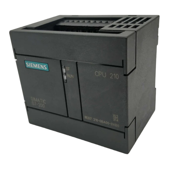
Installing the S7-200 CPU 210 The S7-200 CPU 210 is one of the S7-200 series of micro-programmable logic controllers (Micro PLCs) that can control a variety of automation applications. Figure 1-1 shows an S7-200 CPU 210. The compact design and low cost of the CPU 210 make a perfect solution for controlling small applications. -
Page 12: Product Overview
Installing the S7-200 CPU 210 Product Overview The CPU 210 combines a central processing unit (CPU), power supply, and discrete I/O points into a compact, stand-alone device. The CPU executes the program and stores the data for controlling the automation task or process. -
Page 13: Features Of The Cpu 210
Installing the S7-200 CPU 210 Features of the CPU 210 The CPU 210 is an integral part of the S7-200 family of Micro PLCs. Table 1-1 provides a summary of the major features of the CPU 210. Table 1-1 Features of the CPU 210 Feature CPU 210 Physical Size (length x width x depth) -
Page 14: Pre-Installation Considerations
Installing the S7-200 CPU 210 Pre-installation Considerations Installation Configuration As shown in Figure 1-3, you can install a CPU 210 either on a panel or on a DIN rail. You can mount the CPU 210 either horizontally or vertically. Mounting on a Panel Mounting on a DIN Rail Mounting in a Panel Box CPU 210... -
Page 15: Din Rail Requirements
Installing the S7-200 CPU 210 DIN Rail Requirements The CPU 210 can be installed on a standard DIN rail (DIN EN 50 022). Figure 1-5 shows the dimensions for this DIN rail. 1.0 mm 35 mm (0.039 in.) (1.38 in.) 7.5 mm (0.29 in.) Figure 1-5... -
Page 16: Installing A Cpu 210
Installing the S7-200 CPU 210 Installing a CPU 210 Warning Failure to disable all power to the CPU 210 and related equipment during installation or removal procedures may result in death or serious personal injury, and/or damage to equipment. Disable all power to the CPU 210 and related equipment before installation or removal. Always follow appropriate safety precautions and ensure that power to the CPU 210 is disabled before installation. -
Page 17: Installing A Cpu 210 In A Panel Box
Installing the S7-200 CPU 210 Installing a CPU 210 in a Panel Box To install a CPU 210 in a panel box, follow these steps: 1. Open one of the I/O access covers on the CPU 210. As shown in Figure 1-8, remove the access cover by gently pressing against the access cover until the hinges spring free. -
Page 18: Installing The Field Wiring
Installing the S7-200 CPU 210 Installing the Field Wiring Warning Failure to disable all power to the CPU 210 and related equipment during installation or removal procedures may result in death or serious personal injury, and/or damage to equipment. Disable all power to the CPU 210 and related equipment before installing or removing field wiring. -
Page 19: Grounding And Circuit Referencing Guidelines For Using Isolated Circuits
Installing the S7-200 CPU 210 Grounding and Circuit Referencing Guidelines for Using Isolated Circuits The following items are grounding and circuit guidelines for using isolated circuits: You should identify the reference point (0 voltage reference) for each circuit in the installation, and the points at which circuits with possible different references can connect together. -
Page 20: Using The Optional Field Wiring Connector
Installing the S7-200 CPU 210 Using the Optional Field Wiring Connector The optional field wiring fan-out connector (Figure 1-10) allows for field wiring connections to remain fixed when you remove and re-install the CPU 210. Refer to Appendix F for the order number. - Page 21 Installing the S7-200 CPU 210 Install or equip ungrounded DC power supplies with a resistor and a capacitor in parallel (6) from the power source common to protective earth ground. The resistor provides a leakage path to prevent static charge accumulations, and the capacitor provides a drain for high frequency noise.
-
Page 22: Using Suppression Circuits
Installing the S7-200 CPU 210 Using Suppression Circuits Install or equip inductive loads with suppression circuits that limit voltage rise on loss of power. Use the following guidelines to design adequate suppression. The effectiveness of a given design is dependent on the application, and you must verify it for a particular use. Be sure all components are rated for use in the application. -
Page 23: Installing And Using The Step 7-Micro/Win Version 2.0 Software
In order to use STEP 7-Micro/WIN, you must have the following equipment: Recommended: a personal computer (PC) with an 80486 or greater processor and 8 Mbyte of RAM or a Siemens programming device (such as a PG 740); minimum computer requirement: 80386 with 8 Mbyte of RAM... -
Page 24: Installing The Step 7-Micro/Win Version 2.0 Software
Installing and Using the STEP 7-Micro/WIN Version 2.0 Software Installing the STEP 7-Micro/WIN Version 2.0 Software Pre-installation Instructions Before running the setup procedure, do the following: If a previous version of STEP 7-Micro/WIN is installed, back up all application programs to diskette. -
Page 25: Establishing Communication With The Pds 210
Installing and Using the STEP 7-Micro/WIN Version 2.0 Software Establishing Communication with the PDS 210 Connecting Your Computer to the PDS 210 for PPI Communications Figure 2-1 shows a typical configuration for connecting your personal computer to your PDS 210 with the PC/PPI cable. To establish proper communications between the components, follow these steps: 1. -
Page 26: Setting Up The Communications Parameters
Installing and Using the STEP 7-Micro/WIN Version 2.0 Software Setting Up the Communications Parameters Figure 2-2 shows the Setup Communications dialog box. The first two port options are for PC communication ports. The address for the PDS 210 is 2 and cannot be changed. To set up the communication parameters, follow these steps: 1. -
Page 27: Configuring The Preferences For Step 7-Micro/Win
Installing and Using the STEP 7-Micro/WIN Version 2.0 Software Configuring the Preferences for STEP 7-Micro/WIN Before creating a new project, specify the preferences for your programming environment. To select your preferences, follow these steps: 1. Select the menu command Setup Preferences... -
Page 28: Creating And Saving A Project
Installing and Using the STEP 7-Micro/WIN Version 2.0 Software Creating and Saving a Project Before you create a program, you must create or open a project. When you create a new project, STEP 7-Micro/WIN opens the following editors: Ladder Editor or Statement List Editor (depending on your selected preference) Data Block Editor (not applicable for the PDS 210) Status Chart Symbol Table... -
Page 29: Creating A Program
Installing and Using the STEP 7-Micro/WIN Version 2.0 Software Creating a Program STEP 7-Micro/WIN allows you to create the user program (OB1) with either the Ladder Editor or the Statement List Editor. Entering Your Program in Ladder The Ladder Editor window allows you to write a program using graphical symbols. See Figure 2-5. -
Page 30: Entering Your Program In Statement List
Installing and Using the STEP 7-Micro/WIN Version 2.0 Software Entering Your Program in Statement List The Statement List (STL) Editor is a free-form text editor which allows a certain degree of flexibility in the way you choose to enter program instructions. Figure 2-6 shows an example of a statement list program. -
Page 31: Viewing A Program In Ladder Or Statement List
Installing and Using the STEP 7-Micro/WIN Version 2.0 Software Viewing a Program in Ladder or Statement List You can view a program in either ladder or STL by selecting the menu command View or View Ladder, as shown in Figure 2-7. When you change the view from STL to ladder and back again to STL, you may notice changes in the presentation of the STL program, such as: Instructions and addresses are changed from lower case to upper case. -
Page 32: Downloading A Program
Installing and Using the STEP 7-Micro/WIN Version 2.0 Software Downloading A Program After developing and testing your program on the PDS 210, you must transfer the program to the CPU 210 using the memory cartridge. In the same manner as you could use a diskette to transfer files from one computer to another, you use a memory cartridge to transfer your program from the PDS 210 to the CPU 210. -
Page 33: Copying Your Program To The Memory Cartridge
Installing and Using the STEP 7-Micro/WIN Version 2.0 Software Copying Your Program to the Memory Cartridge You can copy your program to the memory cartridge only when the PDS 210 is powered up and the memory cartridge is installed. (You can install or remove the memory cartridge while the PDS 210 is powered up.) Caution Electrostatic discharge can damage the memory cartridge or the receptacle on the... - Page 34 Installing and Using the STEP 7-Micro/WIN Version 2.0 Software As shown in Figure 2-10, the CPU 210 performs the following tasks after you turn the power on when a memory cartridge is installed in the CPU 210: The M, T, and Q areas of memory are cleared. The current values for the counters (which are stored in the permanent memory) are cleared.
-
Page 35: Using Symbolic Addressing
Installing and Using the STEP 7-Micro/WIN Version 2.0 Software Using Symbolic Addressing The Symbol Table allows you to give symbolic names to inputs, outputs, and internal memory locations. See Figure 2-11. You can use the symbols you have assigned to these addresses in the Ladder Editor, STL Editor, and Status Chart of STEP 7-Micro/WIN. -
Page 36: Editing Functions Within The Symbol Table
Installing and Using the STEP 7-Micro/WIN Version 2.0 Software Editing Functions within the Symbol Table The Symbol Table provides the following editing functions: Edit Cut / Copy / Paste within a cell or from one cell to another. Edit Cut / Copy / Paste one or several adjacent rows. Edit Insert Row(s) above the row containing the cursor. -
Page 37: Using The Status Chart
Installing and Using the STEP 7-Micro/WIN Version 2.0 Software Using the Status Chart The Status Chart editor appears by default as a minimized window icon at the bottom of the main window. To access the Status Chart, double-click the icon, or click the Restore or Maximize button on the icon (in Windows 95). -
Page 38: Debugging And Monitoring Your Program
Installing and Using the STEP 7-Micro/WIN Version 2.0 Software Debugging and Monitoring Your Program Using Single/Multiple Scans to Monitor Your Program You can specify that the PDS 210 execute your program for a limited number of scans (from 1 scan to 65,535 scans). By selecting the number of scans for the PDS 210 to run, you can monitor the program as it changes the process variables. -
Page 39: Error Handling For The Pds 210
Installing and Using the STEP 7-Micro/WIN Version 2.0 Software 2.10 Error Handling for the PDS 210 The PDS 210 classifies errors as either fatal errors or non-fatal errors. You can use STEP 7-Micro/WIN to view the error codes that were generated by the error. Figure 2-16 shows the dialog box that displays the error code and the description of the error. -
Page 40: Responding To Non-Fatal Errors
Installing and Using the STEP 7-Micro/WIN Version 2.0 Software Responding to Non-Fatal Errors Non-fatal errors can degrade some aspect of the PDS 210 performance, but they do not render the PDS 210 incapable of executing your program or from updating the I/O. As shown in Figure 2-16, you can use STEP 7-Micro/WIN to view the error codes that were generated by the non-fatal error. -
Page 41: Getting Started With A Sample Program
Getting Started with a Sample Program You can enter the program for the sample application on a computer running STEP 7-Micro/WIN. To download the program, you must have the equipment shown in Figure 3-1. The size of the sample program is 155 bytes. Program Development Station Computer (PDS 210) -
Page 42: Defining The Requirements For The Application Example
Getting Started with a Sample Program Defining the Requirements for the Application Example Defining the Inputs and Outputs for the Application This chapter describes a sample program for a home security system. As shown in Figure 3-2, the program monitors two zones. Any breach of security results in an alarm being sounded. - Page 43 Getting Started with a Sample Program Rear Entrance Bedroom 2 Bedroom 3 Bedroom 1 Front Entrance Living Room Bath Kitchen Zone 1 Zone 2 Figure 3-2 Sample Application for a Home Security System Inputs Outputs Zone 1 I0.0 System LED Q0.0 Zone 2 I0.1...
-
Page 44: Designing The Control Logic
Getting Started with a Sample Program Designing the Control Logic Creating a program is more involved than just entering the instructions into a file. Individual elements or tasks make up the control logic contained within the program. These elements relate to the various instructions, which are then arranged into networks. This section provides an insight into how the sample program was structured. - Page 45 Getting Started with a Sample Program Zone 1 Zone 2 Armed Panic Alarm When armed turns on, Turn on the alarm and start start the exit timer and the modem dialer. turn on the LED. If not armed and either If the system is armed and the exit timer is >= 90 seconds, Zone 1 or Zone 2 is open, and if either Zone 1 or Zone 2 is open, then start the alert...
-
Page 46: Designing The Control Logic For Arming And Disarming The System
Getting Started with a Sample Program Designing the Control Logic for Arming and Disarming the System Figures 3-5 and 3-6 shows the control logic for arming and disarming the security system. As shown in Figure 3-5, arming the security system activates (enables) the bits of M memory that control the outputs (alarm siren and modem dialer). -
Page 47: Designing The Control Logic For Turning On The Low-Level Alert Notification
Getting Started with a Sample Program Network Use the negative transition of SM0.5 to turn the LED on. NETWORK I0.2 Armed Zone_1 SM0.5 LED_Bit I0.0 I0.1 Zone_2 SM0.5 M0.0, 1 Network Use the positive transition of SM0.5 to turn the LED off. NETWORK I0.2 Armed... -
Page 48: Designing The Control Logic For Turning On The Alarm And Modem Dialer
Getting Started with a Sample Program Designing the Control Logic for Turning On the Alarm and Modem Dialer Because the outputs turn on immediately, the program uses memory bits (M) for storing the results of the control logic. See Figure 3-9. At the end of the program, these bits turn on (or off) the outputs. -
Page 49: Putting The Control Logic Into A Program
Getting Started with a Sample Program Putting the Control Logic into a Program After you have designed the control logic for your application, you arrange the instructions into a program. You can choose either STL or ladder for your program. Figure 3-11 provides a listing of the ladder program for the sample program. - Page 50 Getting Started with a Sample Program Reset everything if the system is disarmed. Network 5 I0.2 I0.3 M0.0 M0.1 M0.2 Q0.3 Network 6 Use the negative transition to turn the LED on. I0.2 I0.0 SM0.5 M0.0 I0.1 Network 7 Use the positive transition to turn the LED off. I0.2 I0.0 SM0.5...
- Page 51 Getting Started with a Sample Program Table 3-2 provides a listing of the STL program for the sample program. This program includes the control logic from Section 3.2. The program ends with the End instruction (MEND). Table 3-2 Sample Program in Statement List Description NETWORK 1 I0.3...
- Page 52 Getting Started with a Sample Program Table 3-2 Sample Program in Statement List, continued NETWORK 9 M0.1 // if the high-level alarm bit has been set Q0.1 // turn on the high-level alarm output NETWORK 10 M0.2 // if the low-level alert bit has been set Q0.2 // turn on the low-level alert output NETWORK 11...
-
Page 53: Creating A Project With Step 7-Micro/Win
Getting Started with a Sample Program Creating a Project with STEP 7-Micro/WIN To create a new project, select the menu command Project New..., as shown in Figure 3-12. The CPU Type dialog box is displayed. Select “PDS 210” from the drop-down list box. -
Page 54: Creating A Symbol Table
Getting Started with a Sample Program Creating a Symbol Table To make programming easier, you can define symbolic names (or symbols) for memory addresses. You use the Symbol Table to define the set of symbols used to represent the absolute addresses in the sample program. To open the Symbol Table editor, double-click the icon, or click the restore or maximize button on the icon (in Windows 95). -
Page 55: Entering The Program
Getting Started with a Sample Program Entering the Program You can enter the program in either statement list (STL) or ladder. You can also use either absolute addressing or symbolic addressing. To enter the program in STL, you open the STL Editor window and start typing the instructions. - Page 56 Getting Started with a Sample Program Refer to Figure 3-16 and follow these steps to enter the first network of the sample program: 1. Click the mouse cursor in the left-most position below the network title. Enter a normally open contact by clicking the F4 toolbar button or by selecting “Contacts” from the family listing and then selecting “Normally Open”...
- Page 57 Getting Started with a Sample Program Refer to Figure 3-17 and follow these steps to enter the output coil that ends the first rung of the first network: 1. Select “Output Coils” from the family listing and select “Set” from the instruction listing. 2.
- Page 58 Getting Started with a Sample Program Refer to Figure 3-18 and follow these steps to enter the two contacts on the second rung of the first network: 1. Select “Contacts” from the family listing and select “>= Integer” from the instruction listing. This inserts a comparison instruction at the cursor position.
- Page 59 Getting Started with a Sample Program Refer to Figure 3-19 and follow these steps to enter a vertical line and to copy the output coil from the first rung: 1. Move the cursor to the horizontal line above the contact for “Armed” (or I0.2). Click the F7 toolbar button to insert a vertical line that connects the first rung with the second rung.
- Page 60 Getting Started with a Sample Program Figure 3-20 shows the remaining steps for finishing the first network. After you have entered the first network, move the cursor to the second network. Refer to Figure 3-11 and enter the remaining networks of the sample program. Lines Vertical Network 1...
-
Page 61: Compiling The Program
Getting Started with a Sample Program Compiling the Program After completing the sample program, check the syntax by selecting the menu command Compile or by clicking the Compile button: If you have entered all the networks correctly as shown in the sample program, you will get a “Compile Successful”... -
Page 62: Creating A Status Chart
Getting Started with a Sample Program Creating a Status Chart To monitor the status of selected elements in the sample program, you create a Status Chart containing the elements you want to monitor while running the program. You can use the Status Chart to monitor and modify the program as it runs on your PDS 210;... -
Page 63: Downloading And Monitoring The Sample Program
Getting Started with a Sample Program Downloading and Monitoring the Sample Program Once you have downloaded your program to the PDS 210, you can use the Debug features to monitor or debug the operation of your program. Downloading the Project to the PDS 210 The PDS 210 must be in STOP mode for you to download a program. -
Page 64: Using The Status Chart To Monitor And Modify The Current Values Of The Program
Getting Started with a Sample Program Using the Status Chart to Monitor and Modify the Current Values of the Program You can use the Status Chart to monitor or modify the current values of any I/O points or memory locations. Reopen the Status Chart window, if necessary, and select the menu command Debug Chart Status On, as shown in Figure 3-23. -
Page 65: Modifying The Sample Program
Getting Started with a Sample Program Modifying the Sample Program You can use the following networks of control logic to modify the sample program. These networks provide the following enhancements to the sample program: If Zone 1 is open, the LED flashes one time. If Zone 2 is open, the LED flashes two times. -
Page 66: Turning The Led On And Off
Getting Started with a Sample Program Turning the LED On and Off The program uses a timer (T1) and the pattern stored in MW3 to turn the LED on and off. The program increments MW1 to count the number of passes through the control logic for flashing the lights;... - Page 67 Getting Started with a Sample Program Network 11 NETWORK LDW= MW1, +1 M4.0 I0.2 M0.0 M4.0 LDW= MW1, +2 M4.1 LDW= MW1, +3 M4.2 M4.1 LDW= MW1, +6 M4.5 LDW= MW1, +7 If the step counter equals a particular M4.6 value and the corresponding bit pattern M4.2 LDW=...
- Page 68 Getting Started with a Sample Program S7-200 Programmable Controller, CPU 210 3-28 C79000-G7076-C235-01...
- Page 69 Basic Concepts for Programming the CPU 210 Before you start to program your application using the CPU 210, you should become familiar with some of its basic operational features. Chapter Overview Section Description Page Guidelines for Designing a Micro PLC System Concepts for Creating a Program Understanding the Scan Cycle of the CPU 210 Understanding the Programming Languages...
-
Page 70: Guidelines For Designing A Micro Plc System
Basic Concepts for Programming the CPU 210 Guidelines for Designing a Micro PLC System There are many methods for designing a Micro PLC system. This section provides some general guidelines that can apply to many design projects. Of course, you must follow the directives of your own company’s procedures and of the accepted practices of your own training and location. -
Page 71: Designing The Safety Circuits
Basic Concepts for Programming the CPU 210 Designing the Safety Circuits Identify equipment requiring hard-wired logic for safety. Control devices can fail in an unsafe manner, producing unexpected startup or change in the operation of machinery. Where unexpected or incorrect operation of the machinery could result in physical injury to people or significant property damage, consideration should be given to to the use of electro-mechanical overrides which operate independently of the CPU 210 to prevent unsafe operations. -
Page 72: Concepts For Creating A Program
Basic Concepts for Programming the CPU 210 Concepts for Creating a Program Relating the Program to Inputs and Outputs Figure 4-2 shows a simple diagram of how an electrical relay diagram relates to the CPU 210. In this example, the state of the operator panel switch for opening the drain is added to the states of other inputs. -
Page 73: Organizing The Program
Basic Concepts for Programming the CPU 210 Organizing the Program As shown in Figure 4-3, a program for the CPU 210 is structured into the following organizational elements: the main program and an optional hardware interrupt routine. The main program stores the instructions that control your application. The instructions in the main program are executed sequentially once per scan of the CPU. -
Page 74: Understanding The Scan Cycle Of The Cpu
Basic Concepts for Programming the CPU 210 Understanding the Scan Cycle of the CPU 210 The basic operation of the CPU 210 is very simple: The CPU reads the status of the inputs. The program that is stored in the CPU uses the inputs to evaluate the control logic. As the program runs, the CPU writes the data to the outputs. -
Page 75: Understanding The Basic Scan Cycle Of The Pds 210
Basic Concepts for Programming the CPU 210 Understanding the Basic Scan Cycle of the PDS 210 The scan cycle for the PDS 210 is similar to the scan cycle for the CPU 210. Because the PDS 210 communicates with STEP 7-Micro/WIN, it must process any communication requests. -
Page 76: Using The Debug Option To Specify The Number Of Scans
Basic Concepts for Programming the CPU 210 Using the Debug Option to Specify the Number of Scans STEP 7-Micro/WIN allows you to debug your program by specifying a number of scans to be run on the PDS 210 before stopping. (See Section 2.9.) You can specify to run one scan or several. -
Page 77: Understanding The Programming Languages
Basic Concepts for Programming the CPU 210 Understanding the Programming Languages The CPU 210 and STEP 7-Micro/WIN support the following programming languages: Statement list (STL) is a set of mnemonic instructions that represent functions of the CPU. Ladder is a graphical language that resembles the electrical relay diagrams for the equipment. -
Page 78: Understanding The Statement List Instructions
Basic Concepts for Programming the CPU 210 Understanding the Statement List Instructions Statement list (STL) is a programming language in which each statement in your program includes an instruction that uses a mnemonic abbreviation to represent a function of the CPU. -
Page 79: Understanding The Addresses Of The Memory Areas
Basic Concepts for Programming the CPU 210 Understanding the Addresses of the Memory Areas The CPU 210 provides 4 digital input points and 4 digital output points. In addition to the I/O, the CPU provides memory areas for storing information. These memory locations have unique addresses that can be accessed by your program. -
Page 80: Addressing The Input Image Register (I)
Basic Concepts for Programming the CPU 210 You can access data in many CPU memory areas (T, C, M, and SM) as words. To access a word of data in the CPU memory, you must specify the address in a similar way to the address for a bit. -
Page 81: Addressing The Timer (T) Memory Area
Basic Concepts for Programming the CPU 210 Addressing the Timer (T) Memory Area Timers are devices that count increments of time. The four timers (T0 to T3) have resolutions (time-base increments) of 100 ms. The current value of each timer is stored as a 16-bit (word) signed integer. -
Page 82: Sample Program Using An Interrupt Routine
Basic Concepts for Programming the CPU 210 Sample Program Using an Interrupt Routine You can use the hardware interrupt of the CPU 210 to control tasks that require high-speed counting functions. For example, you can use the CPU 210 to count a pulse train from an RTD sensor instrument and control a resistance heater. - Page 83 Basic Concepts for Programming the CPU 210 Main Program Ladder Network 1 Network 1 I0.1 M0.0 I0.1 M0.0 T0, +0 MOVW +0, MW2 MOV_W Network 2 SM0.0 M0.0, 1 Network 3 LDW>= T0, +50 Network 2 DISI SM0.0 M0.0 M0.0, 1 Network 1: Turn on timer T0, enable the interrupt routine, and initialize the counter Network 4...
-
Page 84: Using The Analog Adjustment Potentiometer
Basic Concepts for Programming the CPU 210 Using the Analog Adjustment Potentiometer As shown in Figure 4-15, your CPU 210 provides one analog adjustment potentiometer (located under the access cover of the module). You can adjust this potentiometer to increase or decrease values which are stored in bytes of Special Memory (SMW2). Your program can use this read-only value for a variety of functions, such as updating the current value for a timer or a counter, entering or changing the preset values, or setting limits. -
Page 85: Instruction Set
Instruction Set The following conventions are used in this chapter to illustrate the equivalent ladder and statement list instructions: Conditional: executes according to condition of Ladder (LAD) preceding logic representation Unconditional: executes Statement list (STL) without preceding logic representation Chapter Overview Section Description Page... -
Page 86: Valid Ranges For The Cpu 210 And Pds 210
Instruction Set Valid Ranges for the CPU 210 and PDS 210 Valid Operand Ranges Table 5-1 provides the valid ranges of the operands used to access data in the different memory areas. These ranges vary according to the size of the data being accessed. Table 5-1 Operand Ranges Access Method CPU 210 and PDS 210... -
Page 87: Contact Instructions
Instruction Set Contact Instructions Standard Contacts The Normally Open contact is closed (on) when the bit value of address n = 1. In STL, the normally open contact is represented by the Load, And, and Or instructions. These instructions Load, AND, or OR the bit value of address n to the top of the stack. -
Page 88: Compare Word Integer
Instruction Set Compare Word Integer The Compare Word Integer instruction is used to compare two values: n1 = n2, n1 >= n2, or n1 <= n2. Operands: T, C, MW, SMW T, C, MW, SMW, Constant >=I In ladder, the contact is on when the comparison is true. In STL, the instructions Load, AND, or OR a 1 with the top of stack when the comparison is true. -
Page 89: Output
Instruction Set Output Instructions Output When the Output instruction is executed, the specified parameter (n) is turned on. In STL, the output instruction copies the top of the stack to the specified parameter (n). Operands: Q, M Set, Reset When the Set and Reset instructions are executed, the point S_BIT specified by S_BIT is set (turned on) or reset (turned off). -
Page 90: Timer Instructions
Instruction Set Timer Instructions You can use the timer to implement time-based counting functions. The timer times up while the enabling input is on. When the enabling input is off, the timer automatically resets. The timer is best used when you are timing a single interval. On-Delay Timer The On-Delay Timer instruction times up to the maximum value when enabled. -
Page 91: Timer Example
Instruction Set Timer Example I0.2 Network I0.2 T1, 0 Network LDW >= T1, 3 Q0.2 Q0.2 >=I Timing Diagram I0.2 T1 (current) T1 >= 3 T1 >= 3 Q0.2 Figure 5-3 Example of the Timer Instruction M0.0 Network M0.0 //Enable/disable the timer T0, 0 //Select timer T0 Network... -
Page 92: Counter Instructions
Instruction Set Counter Instructions The Up/Down Counter counts up each time the count-up input transitions from off to on, and counts down each time the count-down input transitions from off to on. The counter resets when the reset input turns on. Upon reaching maximum value (32,767), the next rising edge at the count-up input will cause the current count to wrap around to the minimum value (-32,768). -
Page 93: Increment And Decrement Instructions
Instruction Set Increment and Decrement Instructions Increment Word, Decrement Word The Increment Word and Decrement Word instructions add or subtract 1 to or from the input word. INC_W Operands: T, C, MW OUT: T, C, MW DEC_W In ladder: IN + 1 = OUT IN - 1 = OUT In STL: OUT + 1 = OUT... -
Page 94: Move Instruction
Instruction Set Move Instruction Move Word The Move Word instruction moves the input word (IN) to the output word (OUT). The input word is not altered by the move. MOV_W Operands: T, C, MW, SMW, Constant OUT: T, C, MW MOVW IN, OUT Move Examples I0.1... -
Page 95: Program Control Instructions
Instruction Set Program Control Instructions The Unconditional END coil is the last instruction in (or, terminates) the main user program. In STL, the unconditional END operation is represented by the MEND instruction. Operands: None MEND You must terminate the main program with an unconditional END (MEND) instruction. -
Page 96: End And Wdr Example
Instruction Set END and WDR Example Network Network 15 M0.1 M0.1 When M0.1 is on, retrigger the Watchdog Reset (WDR) to allow the scan time to be extended. Network MEND Network 78 Terminate the main program. Figure 5-8 Example of END and WDR Instructions Jump to Label, Label The Jump to Label instruction performs a branch to the specified label (n) within the program. -
Page 97: Logic Stack Instructions
Instruction Set Logic Stack Instructions And Load The And Load instruction combines the values in the first and second levels of the stack using a logical And operation. The result is loaded in the top of stack. After the ALD executes, the stack depth is one less. -
Page 98: 5.10 Interrupt Instructions
Instruction Set 5.10 Interrupt Instructions The CPU 210 has one interrupt event (rising edge of I0.0). To access this event, you must program an interrupt routine (INT 0), and enable the interrupt. The ENI (enable interrupt) instruction must be executed. An interrupt will occur on the next rising edge of I0.0 (after the ENI instruction is executed). -
Page 99: Guidelines And Restrictions For Using The Interrupt Routine
Instruction Set Guidelines and Restrictions for Using the Interrupt Routine Interrupt processing provides quick reaction to an I/O event. You should optimize the interrupt routine to perform a specific task, and then return control to the main routine. By keeping the interrupt routine short, execution is quick, and other processes are not deferred for long periods of time. -
Page 100: Interrupt Example
Instruction Set Interrupt Example Main Program Ladder Network 1 Network 1 I0.1 M0.0 I0.1 M0.0 T0, +0 MOVW +0, MW2 MOV_W Network 2 SM0.0 M0.0, 1 Network 3 LDW>= T0, +50 Network 2 DISI SM0.0 M0.0 M0.0, 1 Network 1: Turn on timer T0, enable the interrupt routine, and initialize the counter Network 4 variable (MW2). - Page 101 CPU 210 Data Sheets Chapter Overview Section Description Page General Technical Specifications CPU 210 DC Power Supply, 24 VDC Inputs, 24 VDC Outputs CPU 210 AC Power Supply, 24 VDC Inputs, Relay Outputs CPU 210 AC Power Supply, AC Inputs, Relay Outputs PDS 210 AC Power Supply, DC Inputs, Relay Outputs A-10 Memory Cartridge 8K x 8...
-
Page 102: Acpu 210 Data Sheets
CPU 210 Data Sheets General Technical Specifications National and International Standards The national and international standards listed below were used to determine appropriate performance specifications and testing for the S7-200 family of products. Table A-1 defines the specific adherence to these standards. Underwriters Laboratories, Inc.: UL 508 Listed (Industrial Control Equipment) Canadian Standards Association: CSA C22.2 Number 142 Certified (Process Control Equipment) - Page 103 CPU 210 Data Sheets Table A-1 Technical Specifications for the S7-200 Family, continued Electromagnetic Compatibility — Immunity IEC 801-2 Electrostatic Discharge 8 kV air discharge to all surfaces and communication port IEC 801-3 Radiated electromagnetic field 26 MHz to 1 GHz 10 V/m, 80% modulation with 1 kHz signal 900 MHz 5 MHz, 10 V/m, 50% duty cycle, 200 Hz repetition frequency...
-
Page 104: Cpu 210 Dc Power Supply, 24 Vdc Inputs, 24 Vdc Outputs
CPU 210 Data Sheets CPU 210 DC Power Supply, 24 VDC Inputs, 24 VDC Outputs Model Number: 6ES7 210-0AA00-0XB0 General Features Input Points Physical Size (L x W x D) 90 x 80 x 62 mm Input Type (IEC 1131-2) Sink/Source (3.54 x 3.15 x 2.44 in.) IEC 1131 Type 1 in Sink... - Page 105 CPU 210 Data Sheets Outputs (20.4 to 28.8 VDC) Power Supply OUTPUTS 24V DC Analog Adjustment Potentiometer Note: Actual component values may vary. 470 ohms 3.3K ohms 24 VDC Power for Input Sensors Location for the Memory Cartridge Inputs (15 to 35 VDC) Figure A-1 Connector Terminal Identification for CPU 210 DC/DC/DC S7-200 Programmable Controller, CPU 210...
-
Page 106: Cpu 210 Ac Power Supply, 24 Vdc Inputs, Relay Outputs
CPU 210 Data Sheets CPU 210 AC Power Supply, 24 VDC Inputs, Relay Outputs Model Number: 6ES7 210-0BA00-0XB0 General Features Input Points Physical Size (L x W x D) 90 x 80 x 62 mm Input Type (IEC 1131-2) Sink/Source (3.54 x 3.15 x 2.44 in.) IEC 1131 Type 1 in Sink mode... - Page 107 CPU 210 Data Sheets Outputs 30 VDC / 250 VAC Power Supply N (-) N (-) L (+) L (+) RELAY L1 85–264 VAC OUTPUTS Analog Adjustment Potentiometer Note: Actual component values may vary. 470 ohms 3.3K ohms 24 VDC Power for Input Sensors Location for the Inputs (15 to 35 VDC)
-
Page 108: Cpu 210 Ac Power Supply, Ac Inputs, Relay Outputs
CPU 210 Data Sheets CPU 210 AC Power Supply, AC Inputs, Relay Outputs Model Number: 6ES7 210-0CA00-0XB0 General Features Input Points Physical Size (L x W x D) 90 x 80 x 62 mm Input Type (IEC 1131-2) Type 1 Sinking (3.54 x 3.15 x 2.44 in.) ON State Range 164 to 265 VAC, 47 to 63 Hz,... - Page 109 CPU 210 Data Sheets Power Supply Outputs 30 VDC / 250 VAC N (-) N (-) L (+) L (+) RELAY OUTPUTS L1 85–264 VAC Analog Adjustment Potentiometer Note: Actual component values may vary. 390 ohms 3.3K ohms 0.1 F Location for the Memory Cartridge Inputs (164 to 265 VAC)
-
Page 110: Pds 210 Ac Power Supply, Dc Inputs, Relay Outputs
CPU 210 Data Sheets PDS 210 AC Power Supply, DC Inputs, Relay Outputs Model Number: 6ES7 210-8XX00-6AA0 General Features Input Points Physical Size (L x W x D) 197 x 80 x 62 mm Input Type (IEC 1131-2) Type 1 Sinking (7.76 x 3.15 x 2.44 in.) ON State Range 15-30 VDC, 4 mA minimum... - Page 111 CPU 210 Data Sheets Outputs (30 VDC / 250 VAC) Power Supply N (-) L (+) RELAY 85–264 OUTPUTS Location of the Analog Adjustment Potentiometer and the Memory Cartridge Note: 1. Actual component values may vary. 2. For AC outputs, connect AC line to the L terminal. 470 ohms 3.3K ohms DC 24V...
-
Page 112: Memory Cartridge 8K X
CPU 210 Data Sheets Memory Cartridge 8K x 8 Model Number: 6ES7 291-8GC00-0XA0 General Features Physical Size (L x W x D) 28 x 10 x 16 mm (1.1 x 0.4 x 0.6 in.) Weight 3.6 g (0.01 lbs.) Power Dissipation 0.5 mW Memory Type EEPROM... -
Page 113: A.7 Memory Cartridge 16K X 8
CPU 210 Data Sheets Memory Cartridge 16K x 8 Model Number: 6ES7 291-8GD00-0XA0 General Features Physical Size (L x W x D) 28 x 10 x 16 mm (1.1 x 0.4 x 0.6 in.) Weight 3.6 g (0.01 lbs.) Power Dissipation 0.5 mW Memory Type EEPROM... -
Page 114: Pc/Ppi Cable
CPU 210 Data Sheets PC/PPI Cable Model Number: 6ES7 901-3BF00-0XA0 General Features Cable Length 5 meters (197 in.) Weight 0.3 kg (0.7 lbs.) Power Dissipation 0.5 W Connector Type PC 9 pin Sub D (socket) 9 pin Sub D (pins) Cable Type RS-232 to RS-485 non-isolated Cable Receive/Transmit Turn-around Time... -
Page 115: Dc Input Simulator
CPU 210 Data Sheets DC Input Simulator Model Number: 6ES7 274-1XH00-0XA0 General Features Physical Size (L x W x D) 91 x 36 x 22 mm (3.6 x 1.4 x 0.85 in.) Weight 0.03 kg (0.06 lb.) Points Note The PDS 210 supports only 4 of the 14 simulator points. 0.1 0.2 DC 24V SENSOR... - Page 116 CPU 210 Data Sheets S7-200 Programmable Controller, CPU 210 A-16 C79000-G7076-C235-01...
- Page 117 Special Memory (SM) The bits of the SM memory not only provide a variety of status and control functions, but also serve as a means of communicating information between the CPU 210 and your program. You can read the special memory as bits or words. The program development station (PDS 210) provides additional words of special memory for diagnostic capabilities.
- Page 118 Special Memory (SM) SMW2: Analog Adjustment SMW2 stores the digital value that represents the position of the analog adjustment potentiometer. You access this value as a word. The CPU 210 samples the analog adjustment potentiometer at least three times a second and has a range of integers from 0 to 255.
- Page 119 Error Handling and Error Codes Non-Fatal Errors (Compile Rule Violations) When you download a program, the PDS 210 compiles the program. If the PDS 210 detects that the program violates a compile rule (such as an illegal instruction), the PDS 210 aborts the download and generates a non-fatal, compile-rule error code.
- Page 120 Error Handling and Error Codes The PDS 210 remains in this condition until the fatal error is corrected. Table C-2 provides a list with descriptions for the fatal error codes that can be read from the PDS 210. Table C-2 Fatal Error Codes and Messages Read from the PDS 210 Error Code Description 0000...
- Page 121 Converting STEP 7-Micro/DOS Files to STEP 7-Micro/WIN Files STEP 7-Micro/WIN allows you to import programs created in the STEP 7-Micro/DOS programming software into Micro/WIN projects. Importing a STEP 7-Micro/DOS Program To import a STEP 7-Micro/DOS program into a STEP 7-Micro/WIN project, follow these steps: 1.
- Page 122 Converting STEP 7-Micro/DOS Files to STEP 7-Micro/WIN Files Import Guidelines and Limitations When you import a Micro/DOS .VPU program file, a copy of the following Micro/DOS files are converted to the Micro/WIN format after you save them: Program files V memory and data (not applicable for the CPU 210 and PDS 210) Synonyms and descriptors Status chart that has the same name as the project The following actions occur when you import a Micro/DOS program into a Micro/WIN project:...
- Page 123 Execution Times for STL Instructions Table E-1 lists the basic execution times of the STL instructions for the CPU 210. The calculation of the basic execution time for an STL instruction shows the time required for executing the logic, or function, of the instruction when power flow is present (where the top-of-stack value is ON or 1).
- Page 124 Execution Times for STL Instructions Execution Times for the STL Instructions (in µs), continued Table E-1 Instruction Description On (µs) Off (µs) Load valid for I, M, SM Load Not valid for I, M, SM LDW <= Load Word if less than or equal LDW = Load Word if equal LDW >=...
-
Page 125: Dc Input Simulator
CPU 210 Order Numbers CPU and Program Development Station Order Number CPU 210 DC Power Supply, 24 VDC Inputs, 24 VDC Outputs 6ES7 210-0AA00-0XB0 CPU 210 AC Power Supply, 24 VDC Inputs, Relay Outputs 6ES7 210-0BA00-0XB0 CPU 210 AC Power Supply, AC Inputs, Relay Outputs 6ES7 210-0CA00-0XB0 PDS 210 AC Power Supply, 24 VDC Inputs, Relay Outputs 6ES7 210-8XX00-6AA0... - Page 126 CPU 210 Order Numbers S7-200 Programmable Controller, CPU 210 C79000-G7076-C235-01...
- Page 127 Index Absolute addressing, 4-4 Baud rate, 2-3 bit memory. See special memory (SM) bits AC installation, guidelines, 1-10 Access cover Bit memory (M), 4-11 location of the analog adjustment addressing, 4-12 potentiometer, 4-16 Bit.byte addressing, 4-11 removing, 1-7 Boxes, represented in ladder, 4-9 Accessing data analog adjustment value in special memory (SM), B-2...
- Page 128 Index Connector terminal CPU 210 CPU 210 AC/AC/Relay, A-9 agency approvals, A-2 CPU 210 AC/DC/Relay, A-7 analog adjustment CPU 210 DC/DC/DC, A-5 location of the potentiometer, 4-16 PDS 210, A-11 value stored in special memory (SM), B-2 Considerations basic operation, 4-4 AC installation, 1-10 compile rule violations, C-1 converting files to STEP 7-Micro/WIN, D-2...
-
Page 129: Index Index
Index Creating a program, 2-7–2-9, 3-1–3-25 Disable Interrupt (DISI) instruction, 5-14–5-17 creating a project, 2-6 disabling and enabling interrupts, 5-14 interrupt routine, 4-14 Displaying status in ladder, 2-16 high-speed counter example, 4-14–4-16, Downloading a program 5-16 CPU 210, 2-11 Creating networks, 2-7, 2-8 PDS 210, 2-10–2-12 Current value sample program, 3-23... - Page 130 Index Error handling Guidelines fatal errors, 2-17–2-19, C-1 AC installation, 1-10 non-fatal errors, C-1 case-sensitive symbols, 2-13 non-fatal errors, 2-17–2-19 creating a program with STL, 2-8 responding to errors, 2-17–2-19, C-1 DC installation, 1-10 restarting the CPU after a fatal error, designing a PLC system, 4-2–4-3 2-17–2-19 entering symbolic addresses, 2-13...
- Page 131 Index Input simulator Outputs, 5-5 order number, F-1 Positive Transition (EU), 5-3 specifications, A-15 Program Control, 5-11–5-12 Inputs, basic operation, 4-4 Reset (R), 5-5 Inserting an instruction, 3-16–3-20 Return from Interrupt (RETI), 4-5, 5-14–5-17 Inserting and deleting rows Set (S), 5-5 in a Status Chart, 2-15 standard contacts, 5-3 in a Symbol Table, 2-14...
- Page 132 Index Logic Stack instructions, 5-13 And Load (ALD), 5-13 LAD. See Ladder or Program effect on logic stack, 5-13 Ladder example, 5-13–5-15 basic elements, 4-9 operation, 5-13 boxes, 4-9 Or Load (OLD), 5-13 changing to STL, 2-9 effect on logic stack, 5-13 changing elements in a program, 2-7, 3-16–3-20 coils, 4-9...
- Page 133 Index Mounting Outputs agency certifications and specifications, A-3 addressing, 4-12 clearance requirements, 1-4 basic operation, 4-4 dimensions represented in ladder, 4-9 CPU 210, 1-5 writing to, 4-6–4-9 DIN rail, 1-5 Overview PDS 210, 1-5 CPU 210, 1-1–1-4 in a panel box, 1-7 PDS 210, 1-1–1-4 on a DIN rail, 1-6 on a panel, 1-6...
- Page 134 Index scan times in special memory (SM), B-2 executing, 4-6–4-9 special memory (SM), B-1 guidelines and limitations for converting files, specifications, A-10 DC input simulator, A-15 high-speed counter example, 4-14–4-16, 5-16 summary of features, 1-2 importing files from STEP 7-Micro/DOS, D-1 transporting a program to CPU 210, languages, 4-9–4-11 2-10–2-12...
- Page 135 Index Right mouse button Screw size for installation, 1-6 Status Chart editor, 2-15 Set (S) instruction, 5-5 Symbol Table, 2-14 Setting the baud rate, 2-3 Rungs of logic. See Networks Setting up communication parameters, 2-4 selecting preferences in STEP 7-Micro/WIN, Single read (Status Chart option), 2-15 S7-200, technical specifications, A-2 See also Continuous read;...
- Page 136 Index program examples program examples contact instructions, 5-4 contact instructions, 5-4 counter, 5-8 counter, 5-8 End (MEND), 5-12 End (MEND), 5-12 high-speed counter, 4-14–4-16, 5-16 high-speed counter, 4-14–4-16, 5-16 increment/decrement word, 5-9 increment/decrement word, 5-9 interrupt, 4-14–4-16, 5-16 interrupt, 4-14–4-16, 5-16 jump to label, 5-12 jump to label, 5-12 logic stack (ALD and OLD), 5-13...
- Page 137 Index User manual, order number, F-1 Using the Ladder Editor, 3-15–3-20 Terminating the main program segment, 5-11 Time of last scan, stored in special memory (SM), Timer instructions, 5-6–5-7 accessing the current value, 4-13 Valid ranges for CPU 210, 1-3, 4-11–4-13, 5-2 addressing, 4-13 current value, 4-13, 5-6 device number, 4-12...
- Page 138 Index S7-200 Programmable Controller, CPU 210 Index-12 C79000-G7076-C235-01...
- Page 139 Siemens AG AUT E 146 Östliche Rheinbrückenstr. 50 D-76181 Karlsruhe Federal Republic of Germany From: Your Name: _ _ _ _ _ _ _ _ _ _ _ _ _ _ _ _ _ _ _ _ _ _ _ _ _ _ _ _ _...
- Page 140 Your comments and recommendations will help us to improve the quality and usefulness of our publications. Please take the first available opportunity to fill out this questionnaire and return it to Siemens. Please give each of the following questions your own personal mark within the range from 1 (very good) to 5 (poor).
Need help?
Do you have a question about the Simatic S7-200 CPU 210 and is the answer not in the manual?
Questions and answers