WAGO SYSTEM 750 User Manual
3-phase power measurement module
Hide thumbs
Also See for SYSTEM 750:
- User manual ,
- Manual (450 pages) ,
- User's installation and configuration (335 pages)
Table of Contents
Advertisement
Quick Links
WAGO-I/O-SYSTEM 750
Pos : 2 /D okumentati on allgemein/Ei nband/Ei nband H andbuch - Fronts eite 2015 - mit Doc Variabl en (Standar d) @ 9\mod_1285229289866_0.doc x @ 64941 @ @ 1
Manual
750-493(/xxx-xxx)
3-Phase Power Measurement Module
Version 1.2.0
Pos : 3 /Alle Serien (Allgemeine M odul e)/Hinweise z ur Dokumentation/Impres sum für Standardhandbüc her - allg. Angaben, Ansc hriften, Tel efonnummer n und E-Mail-Adres sen @ 3\mod_1219151118203_21.doc x @ 21060 @ @ 1
Advertisement
Chapters
Table of Contents

Related Manuals for WAGO SYSTEM 750


Summary of Contents for WAGO SYSTEM 750
- Page 1 WAGO-I/O-SYSTEM 750 Pos : 2 /D okumentati on allgemein/Ei nband/Ei nband H andbuch - Fronts eite 2015 - mit Doc Variabl en (Standar d) @ 9\mod_1285229289866_0.doc x @ 64941 @ @ 1 Manual 750-493(/xxx-xxx) 3-Phase Power Measurement Module Version 1.2.0...
- Page 2 WAGO-I/O-SYSTEM 750 750-493 3-Phase Power Measurement Module © 2015 by WAGO Kontakttechnik GmbH & Co. KG All rights reserved. WAGO Kontakttechnik GmbH & Co. KG Hansastraße 27 D-32423 Minden Phone: +49 (0) 571/8 87 – 0 Fax: +49 (0) 571/8 87 – 1 69 E-Mail: info@wago.com...
-
Page 3: Table Of Contents
2.1.1 Subject to Changes ................11 2.1.2 Personnel Qualifications ..............11 2.1.3 Use of the WAGO-I/O-SYSTEM 750 in Compliance with Underlying Provisions ................... 11 2.1.4 Technical Condition of Specified Devices ......... 12 Safety Advice (Precautions) ..............13 Device Description ..................15 View ...................... - Page 4 8.1.4 "Energy" Tab ..................65 8.1.5 "Factory Settings" Tab ............... 66 8.1.6 Register Assignment ................67 Displaying the Measured Values via WAGO-I/O-CHECK ....70 Diagnostics ....................77 Appendix ..................... 78 10.1 CSV Data File “Snapshot” ..............78 10.2 CSV Data File “Measurement Recording” ..........80 Use in Hazardous Environments ..............
-
Page 5: Wago-I/O-System 750 Table Of Contents
WAGO-I/O-SYSTEM 750 Table of Contents 750-493 3-Phase Power Measurement Module List of Tables ......................95 === Ende der Liste für T extmar ke Verzeic hnis_vor ne === Manual Version 1.2.0... -
Page 6: Notes About This Documentation
Pos : 10 /Serie 750 ( WAGO-I/O-SYST EM)/Hi nweis e z ur D okumentati on/Gültigkeits bereic h/Gültig keits ber eich Dokumentation Bus kl emme 750- xxxx, Standar dversi on und aufgelistete Varianten @ 14\mod_1358944038682_21.doc x @ 109354 @ @ 1... -
Page 7: Copyright
Reproduction, translation, electronic and phototechnical filing/archiving (e.g., photocopying) as well as any amendments require the written consent of WAGO Kontakttechnik GmbH & Co. KG, Minden, Germany. Non-observance will involve the right to assert damage claims. Pos : 16.2 /Dokumentation allgemei n/Glieder ungs elemente/---Seitenwechs el--- @ 3\mod_1221108045078_0.doc x @ 21810 @ @ 1 Manual Version 1.2.0... -
Page 8: Symbols
Notes about this Documentation WAGO-I/O-SYSTEM 750 750-493 3-Phase Power Measurement Module Pos : 16.3 /All e Seri en ( Allgemei ne Module)/Ü bers chriften für alle Serien/Hinweis e z ur Dokumentation/Symbol e - Ü bersc hrift 2 @ 13\mod_1351068042408_21.doc x @ 105270 @ 2 @ 1 Symbols Pos : 16.4.1 /All e Serien ( Allgemei ne Module)/Wic htige Erläuterungen/Sicherheits- und sons tige Hinweis e/Gefahr/Gefahr: _War nung vor Personenschäden allgemei n_ - Erl äuter ung @ 13\mod_1343309450020_21.doc x @ 101029 @ @ 1... - Page 9 WAGO-I/O-SYSTEM 750 Notes about this Documentation 750-493 3-Phase Power Measurement Module Additional Information: Refers to additional information which is not an integral part of this documentation (e.g., the Internet). Pos : 16.5 /Dokumentation allgemei n/Glieder ungs elemente/---Seitenwechs el--- @ 3\mod_1221108045078_0.doc x @ 21810 @ @ 1 Manual Version 1.2.0...
-
Page 10: Number Notation
Font Conventions Table 4: Font Conventions Font Type Indicates italic Names of paths and data files are marked in italic-type. e.g.: C:\Program Files\WAGO Software Menu Menu items are marked in bold letters. e.g.: Save > A greater-than sign between two names means the selection of a menu item from a menu. -
Page 11: Important Notes
PLC programming. Pos : 19.5 /Serie 750 (WAGO-I/O-SYST EM)/Wic htige Erläuterungen/Bes timmungsgemäß e Verwendung Bes ti mmungsgemäße Verwendung 750-xxxx - Ü berschrift 3 und Inhal t @ 3\mod_1224064151234_21.doc x @ 24070 @ 3 @ 1 2.1.3... -
Page 12: Technical Condition Of Specified Devices
750-493 3-Phase Power Measurement Module Appropriate housing (per 94/9/EG) is required when operating the WAGO-I/O- SYSTEM 750 in hazardous environments. Please note that a prototype test certificate must be obtained that confirms the correct installation of the system in a housing or switch cabinet. -
Page 13: Safety Advice (Precautions)
Pos : 19.10 /Serie 750 ( WAGO-I/O-SYST EM)/Wichtig e Erl äuter ung en/Sic her hei ts- und s onstige Hinweise/Gefahr/Gefahr: Berührungssc hutz vorsehen 750-0493/0494/Gefahr: Ber ühr ungss chutz vors ehen 750- 0493/0494/0495 @ 15\mod_1366120208015_21.doc x @ 117160 @ @ 1... - Page 14 Important Notes WAGO-I/O-SYSTEM 750 750-493 3-Phase Power Measurement Module Protect the components against materials having seeping and insulating properties! The components are not resistant to materials having seeping and insulating properties such as: aerosols, silicones and triglycerides (found in some hand creams).
-
Page 15: Device Description
Device Description Pos : 22 /Serie 750 ( WAGO-I/O-SYST EM)/Ger ätebesc hrei bung/Ei nlei tung/Analogei ngangs klemmen/Gerätebeschr eibung - Ei nleitung 750- 0493 @ 13\mod_1346315482161_21.doc x @ 102130 @ @ 1 The 3-phase power measurement module (also called I/O module) measures the electrical data in a 3-phase supply network. -
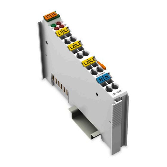
Page 16: View
Figure 1: View Pos : 26 /Serie 750 ( WAGO-I/O-SYST EM)/Ger ätebesc hrei bung/Ansic ht/Ansic ht C ageCl amp® _Leg ende mit LED s_ohne Leis tungs kontakte @ 16\mod_1371816091053_21.doc x @ 124052 @ @ 1 Table 5: Legend for Figure “View”... -
Page 17: Connectors
Pos : 30.3 /Serie 750 (WAGO-I/O-SYST EM)/Wic htige Erläuterungen/Sicherheits- und sonstig e Hinweis e/Achtung/Achtung: ESD - Auf g ute Erdung der U mgebung ac hten! @ 7\mod_1266318538667_21.doc x @ 50708 @ @ 1 Ensure that the environment is well grounded! The devices are equipped with electronic components that may be destroyed by electrostatic discharge. -
Page 18: Cage Clamp
WAGO-I/O-SYSTEM 750 750-493 3-Phase Power Measurement Module Pos : 34 /Serie 750 ( WAGO-I/O-SYST EM)/Ger ätebesc hrei bung/Ansc hl üss e/CAGE CLAMP- Anschl üss e - Ü berschrift 3 @ 6\mod_1256296337770_21.doc x @ 43674 @ 3 @ 1 ® 3.2.3... -
Page 19: Display Elements
Operating Elements Pos : 40 /Serie 750 ( WAGO-I/O-SYST EM)/Ger ätebesc hrei bung/Bedienel emente/Bedi enel emente Bus kl emme 750- xxxx nic ht vor handen @ 4\mod_1236322031125_21.doc x @ 28063 @ @ 1 The I/O module 750-493 has no operating elements. -
Page 20: Schematic Diagram
Pos : 42 /All e Seri en (Allgemei ne Module)/Ü berschriften für alle Serien/Gerätebesc hreibung/Sc hematisches Sc haltbil d - Ü bersc hrift 2 @ 4\mod_1240984441312_21.doc x @ 31967 @ 2 @ 1 Schematic Diagram Pos : 43 /Serie 750 ( WAGO-I/O-SYST EM)/Ger ätebesc hrei bung/Schematisc he Sc haltbil der/Anal ogeing angs kl emmen/Sc hematisc hes Sc haltbild 750-0493 @ 13\mod_1348574311920_21.doc x @ 103381 @ @ 1 Figure 5: Schematic Diagram... -
Page 21: Technical Data
Pos : 45 /All e Seri en (Allgemei ne Module)/Ü berschriften für alle Serien/Gerätebesc hreibung/Technisc he Daten - Ü berschrift 2 @ 3\mod_1232967587687_21.doc x @ 26924 @ 2 @ 1 Technical Data Pos : 46.1 /Serie 750 (WAGO-I/O-SYST EM)/Ger ätebesc hrei bung/T echnisc he Daten/Anal ogeing angs kl emmen/T ec hnis che D aten 750-0493 @ 13\mod_1348667756744_21.doc x @ 103558 @ 33333 @ 1 3.6.1 Dimensions and Weight Table 7: Technical Data ‒... -
Page 22: Measuring Signal Processing
Pos : 46.4 /Serie 750 (WAGO-I/O-SYST EM)/Ger ätebesc hrei bung/T echnisc he Daten/Ansc hluss tec hni k/T ec hnisc he D aten Verdr ahtungsebene CC - 0,08 bis 2,5mm2 @ 17\mod_1380121238809_21.doc x @ 132780 @ @ 1 Table 13: Technical Data – Field Wiring ®... -
Page 23: Climatic Environmental Conditions
WAGO-I/O-SYSTEM 750 Device Description 750-493 3-Phase Power Measurement Module 3.6.7 Climatic Environmental Conditions Table 14: Technical Data – Climatic Environmental Conditions Operating temperature range 0 °C … 55 °C Operating temperature range for −20 °C … +60 °C components with extended... -
Page 24: Approvals
Pos : 49 /Serie 750 ( WAGO-I/O-SYST EM)/Ger ätebesc hrei bung/Z ulass ungen/Allgemei n/Z ulass ungen Bus kl emme 750- xxxx Allgemein, Standardversi on und all e Vari anten - Einl eitung @ 3\mod_1233911570312_21.doc x @ 27390 @ @ 1... -
Page 25: Standards And Guidelines
Standards and Guidelines Pos : 59 /Serie 750 ( WAGO-I/O-SYST EM)/Ger ätebesc hrei bung/N ormen und Ric htlini en/Nor men und Ric htlini en Bus kl emme 750-xxxx, ohne Variantenang abe - Einl eitung @ 7\mod_1274278887584_21.doc x @ 56645 @ @ 1 750-493 I/O modules meet the following standards and guidelines: Pos : 60 /All e Seri en (Allgemei ne Module)/N or men und Ric htli nien/Ex(i)-Normen/Expl osi ons fähige Atmos phäre EN 60079-0 @ 14\mod_1360841627885_21.doc x @ 111880 @ @ 1... -
Page 26: Process Image
Process Image Pos : 67 /Serie 750 ( WAGO-I/O-SYST EM)/Proz ess abbild Kl emmenbus /Analogei ngangs klemmen/Pr ozessabbild 750- 0493 @ 5\mod_1251702231515_21.doc x @ 41084 @ 2222 @ 1 The 750-493 I/O module provides, on 3 logical channels, a maximum of 9 bytes input and 9 bytes output process data to a fieldbus coupler/controller. -
Page 27: Simple Process Image
WAGO-I/O-SYSTEM 750 Process Image 750-493 3-Phase Power Measurement Module Simple Process Image Each input data word in a simple process image is assigned to one channel and can only read measured values from this channel. Table 16: Simple Process Image... -
Page 28: Flexible Process Image
Flexible Process Image An input data word in a flexible process image can read measured values from any channel. The flexible process image is enabled via WAGO-I/O-CHECK on the „Phase L1“, „Phase L2“ and „Phase L3“ tabs. 1st Example: Reading out the current (rms value), voltage (rms value) and active power of... -
Page 29: Control And Status Bytes
WAGO-I/O-SYSTEM 750 Process Image 750-493 3-Phase Power Measurement Module Control and Status Bytes Table 17: Control Byte C0 Control Byte C0 Bit 7 Bit 6 Bit 5 Bit 4 Bit 3 Bit 2 Bit 1 Bit 0 Reg_Com Reserved Channel_ID... -
Page 30: Table 18: Status Byte S0
Process Image WAGO-I/O-SYSTEM 750 750-493 3-Phase Power Measurement Module Table 18: Status Byte S0 Status Byte S0 Bit 7 Bit 6 Bit 5 Bit 4 Bit 3 Bit 2 Bit 1 Bit 0 Reg_Com Err_L1 Channel_ID ProcDat_ID ProcDat_ Process data index for the physical variable which was read out using input data word 1. -
Page 31: Table 19: Control Byte C1
WAGO-I/O-SYSTEM 750 Process Image 750-493 3-Phase Power Measurement Module Table 19: Control Byte C1 Control Byte C1 Bit 7 Bit 6 Bit 5 Bit 4 Bit 3 Bit 2 Bit 1 Bit 0 Reg_Com Reserved Channel_ID ProcDat_ID ProcDat_ Here, enter the process data index for the physical variable you wish to read out using input data word 2. -
Page 32: Table 20: Status Byte S1
Process Image WAGO-I/O-SYSTEM 750 750-493 3-Phase Power Measurement Module Table 20: Status Byte S1 Status Byte S1 Bit 7 Bit 6 Bit 5 Bit 4 Bit 3 Bit 2 Bit 1 Bit 0 Reg_Com Err_L2 Channel_ID ProcDat_ID ProcDat_ Process data index for the physical variable which was read out using input data word 2. -
Page 33: Table 21: Control Byte C2
WAGO-I/O-SYSTEM 750 Process Image 750-493 3-Phase Power Measurement Module Table 21: Control Byte C2 Control Byte C2 Bit 7 Bit 6 Bit 5 Bit 4 Bit 3 Bit 2 Bit 1 Bit 0 Reg_Com Reserved Channel_ID ProcDat_ID ProcDat_ Here, enter the process data index for the physical variable you wish to read out using input data word 3. -
Page 34: Table 22: Status Byte S2
Process Image WAGO-I/O-SYSTEM 750 750-493 3-Phase Power Measurement Module Table 22: Status Byte S2 Status Byte S2 Bit 7 Bit 6 Bit 5 Bit 4 Bit 3 Bit 2 Bit 1 Bit 0 Reg_Com Err_L3 Channel_ID ProcDat_ID ProcDat_ Process data index for the physical variable which was read out using input data word 3. -
Page 35: Function Description
Pos : 69 /All e Seri en (Allgemei ne Module)/Ü berschriften für alle Serien/F unktions bes chr eibungF unktions beschr eibung - Übersc hrift 1 @ 4\mod_1239025975389_21.doc x @ 30003 @ 1 @ 1 Function Description Pos : 70 /Serie 750 ( WAGO-I/O-SYST EM)/F unktions beschr eibung/Funkti onsbesc hrei bung 750-0493 @ 14\mod_1361260872587_21.doc x @ 112240 @ 2222 @ 1 0493 @ 14\mod_1361260872587_21.doc x @ 112240 @ 2222 @ 4... -
Page 36: Figure 6: Rms Value Calculation (Example, Not To Scale)
RMS values for current and voltage can be generated by the measuring cycle time setting. If a time of 40 ms is set in WAGO-I/O-CHECK, there is averaging of 2 RMS values, a value of 500 ms is set, there is averaging of 13 RMS values (500/39 = 12.82). -
Page 37: Figure 7: 4-Quadrant Display Of Active And Reactive Power
The I/O module can be configured, so that the cos phi is output with or without sign (see section "Commissioning" > "Configuration with WAGO-I/O-CHECK"). If a sign is put out, it is not the information acquisition (+) or delivery (-) of active power (P), but a statement on the load on the network: •... - Page 38 Function Description WAGO-I/O-SYSTEM 750 750-493 3-Phase Power Measurement Module Apparent Power and Reactive Power Not all loads are purely resistive in real supply networks. Phase shifting therefore occurs between the current and the voltage. However, this does not affect the method for determining the RMS values for current and voltage previously described.
-
Page 39: Representation Of The Measured Values In The Process Image (Pi)
WAGO-I/O-SYSTEM 750 Function Description 750-493 3-Phase Power Measurement Module Representation of the Measured Values in the Process Image (PI) The I/O module records and calculates numerous measured values. Up to 3 measured values can be represented in the process image (PI). The selection of these ones is made with the process data indices in control bytes C0, C1 and C2 in the output data. - Page 40 Function Description WAGO-I/O-SYSTEM 750 750-493 3-Phase Power Measurement Module Minimum value active power L2 Int16 0.1W / LSB 0.5W / LSB Minimum value active power L3 Int16 0.1W / LSB 0.5W / LSB Energy Setup with WAGO-I/O-CHECK Active energy L1...
- Page 41 If the bit is set to 1, user scaling is enabled (on) and the transformation ratio is already taken into account in the I/O module. The transformation ratio is set using WAGO-I/O-CHECK or in Register 37. The divisor of the CTR (D-CTR) is set in the register, i.e. according to the examples above: •...
- Page 42 Function Description WAGO-I/O-SYSTEM 750 750-493 3-Phase Power Measurement Module The decisive factor is the maximum representable current value in the process image. If the transformation ratio is 500:1 A, for example, the resulting D-CTR of 500 cannot be taken into account in the I/O module 750-493 (1A) directly via active user scaling, likewise a D-CTR of 100 at a transformation ratio of 500:5 A in 750-493/000-001 (5A).
- Page 43 WAGO-I/O-SYSTEM 750 Function Description 750-493 3-Phase Power Measurement Module B. User Scaling ON, Measurement with Current Transformer Current 750-493 750-493/000-001 Register 32, bit 0 Register 37 (D-CTR) 0x002D (45) 0x0028 (40) Process value 0x96A1 (38561) 0x60FB (24827) Scaling factor PI 0.001 A / LSB...
- Page 44 Function Description WAGO-I/O-SYSTEM 750 750-493 3-Phase Power Measurement Module Active Power 750-493 750-493/000-001 Register 32, bit 0 Register 37 (D-CTR) 0x0001 (1) 0x0001 (1) Process value 0x03D2 (978) 0x0776 (1910) Scaling factor PI 0.1 W / LSB 0.5 W / LSB...
- Page 45 WAGO-I/O-SYSTEM 750 Function Description 750-493 3-Phase Power Measurement Module Active Power 750-493 750-493/000-001 Register 32, bit 0 Register 37 (D-CTR1) 0x0032 (50) 0x0032 (50) Process value 0x5486 (21638) 0xFFFF (65535) Scaling factor PI 0.1 W / LSB 0.5 W / LSB...
-
Page 46: Measuring Errors And Accuracy
Function Description WAGO-I/O-SYSTEM 750 750-493 3-Phase Power Measurement Module Measuring Errors and Accuracy The measuring errors of the I/O module are specified in the table below. The values already take into account the errors caused by the connection method (single-ended 0.1%) and the calibration tolerance (0.1%). They apply to the entire temperature range of 0 to 55 °C and to frequencies of 45 to 65 Hz. -
Page 47: Mounting
I/O modules with fewer power contacts. Pos : 73.2 /Serie 750 (WAGO-I/O-SYST EM)/Wic htige Erläuterungen/Sicherheits- und sonstig e Hinweis e/Vorsic ht/Vorsicht: Verl etz ungsgefahr durc h s charfkantige M ess er kontakte! @ 6\mod_1256193279401_21.doc x @ 43414 @ @ 1 Risk of injury due to sharp-edged blade contacts! The blade contacts are sharp-edged. -
Page 48: Inserting And Removing Devices
WAGO-I/O-SYSTEM 750 750-493 3-Phase Power Measurement Module Pos : 73.6 /Serie 750 (WAGO-I/O-SYST EM)/M ontieren/D emontieren/Geräte einfüg en und entfer nen - Ü berschrift 2 @ 3\mod_1231768483250_21.doc x @ 25950 @ 2 @ 1 Inserting and Removing Devices Pos : 73.7 /All e Seri en ( Allgemei ne Module)/Wic htige Erläuterungen/Sicherheits- und sons tige Hi nweis e/Ac htung/Achtung: Arbeiten an Ger äten nur s pannungsfr ei durc hführ en! @ 6\mod_1256193963573_21.doc x @ 43426 @ @ 1 Perform work on devices only if they are de-energized! Working on energized devices can damage them. -
Page 49: Removing The I/O Module
WAGO-I/O-SYSTEM 750 Mounting 750-493 3-Phase Power Measurement Module Pos : 73.10 /Serie 750 ( WAGO-I/O-SYST EM)/Monti eren/D emonti eren/Bus kl emme entfer nen @ 4\mod_1239169375203_21.doc x @ 30334 @ 3 @ 1 6.2.2 Removing the I/O Module Remove the I/O module from the assembly by pulling the release tab. -
Page 50: Connect Devices
Connect Devices Pos : 76 /Serie 750 ( WAGO-I/O-SYST EM)/Ans chli eßen/Leiter an C AGE C LAM P ans chli eßen ( allgemei n) - Übersc hrift 2 und Text @ 3\mod_1225448660171_21.doc x @ 24928 @ 2 @ 1 ®... -
Page 51: Voltage Measurement
Voltage Measurement Pos : 79 /Serie 750 ( WAGO-I/O-SYST EM)/Ans chli eßen/Anschl uss beispi ele/Anal ogei ngangs kl emmen/Spannungsmess ung 750-0493, - 0494 @ 16\mod_1372770254968_21.doc x @ 125343 @ @ 1 In order to measure the 3 phase voltages of a supply network, connect its 4 wires ®... -
Page 52: Current Measurement
Pos : 81 /All e Seri en (Allgemei ne Module)/Ü berschriften für alle Serien/__ noc h nic ht ei ns ortierte Ü berschriften müss en noc h eins orti ert werden __/Strommess ung - Übersc hrift 2 @ 13\mod_1346248472189_21.doc x @ 102101 @ 2 @ 1 Current Measurement Pos : 82 /Serie 750 ( WAGO-I/O-SYST EM)/Ans chli eßen/Anschl uss beispi ele/Anal ogei ngangs kl emmen/Str ommess ung 750-0493 @ 16\mod_1372769974422_21.doc x @ 125339 @ 3344443 @ 1 7.3.1... -
Page 53: Current Transformers
WAGO-I/O-SYSTEM 750 Connect Devices 750-493 3-Phase Power Measurement Module 7.3.2 Current Transformers For measuring currents greater than 1 A resp. 5 A you have to use external current transformers. Normally, the selection of the current transformers is not a critical factor. The... -
Page 54: Protection Against Shock Hazard Voltages
Connect Devices WAGO-I/O-SYSTEM 750 750-493 3-Phase Power Measurement Module connected measuring instruments. FS shall be max. 10 for the 1 A module resp. max. 5 for the 5 A module. Note the max. continuous measuring current of 1 A resp. 5 A! The max. -
Page 55: Additional Measuring Instruments In The Current Path
WAGO-I/O-SYSTEM 750 Connect Devices 750-493 3-Phase Power Measurement Module 7.3.3 Additional Measuring Instruments in the Current Path Please note that adding measuring instruments (such as ammeters) in the current path can substantially increase the total apparent power. ® In addition, the CAGE CLAMP IN of the I/O module must form a star point (neutral) for the three secondary windings. -
Page 56: Power Measurement
Pos : 84 /All e Seri en (Allgemei ne Module)/Ü berschriften für alle Serien/__ noc h nic ht ei ns ortierte Ü berschriften müss en noc h eins orti ert werden __/Leis tungs messung - Ü bersc hrift 2 @ 13\mod_1346327054898_21.doc x @ 102149 @ 2 @ 1 Power Measurement Pos : 85 /Serie 750 ( WAGO-I/O-SYST EM)/Ans chli eßen/Anschl uss beispi ele/Anal ogei ngangs kl emmen/Leistungs mess ung 750-0493 @ 24\mod_1443094930995_21.doc x @ 192428 @ 33 @ 1 7.4.1 Power Measurement on a Machine ®... -
Page 57: Commissioning
Commissioning Pos : 88 /Serie 750 ( WAGO-I/O-SYST EM)/In Betrieb nehmen/Parametrier en mit WAGO- I/O-CH ECK/Parametrier en mit WAGO-I/O-CH ECK 750-0493 @ 13\mod_1355128769520_21.doc x @ 107450 @ 233333 @ 1 The I/O module latched in the bus node and wired for the measurement can be put into operation using the WAGO-I/O-CHECK software for Windows. -
Page 58: Configuration With Wago-I/O-Check
Configuration with WAGO-I/O-CHECK Right-click on the image of the I/O module and select the [Settings] menu item. See the figure below: Figure 15: WAGO-I/O-CHECK User Interface, Bus Node with I/O Module The "3-phase power measurement" dialog opens. See figure below. Manual... -
Page 59: Figure 16: "3-Phase Power Measurement" Dialog
[Calibration] Opens the calibration dialog. More information is available from the WAGO Support. The buttons for the individual measured value views appear in the menu (2). The status bar (3) displays the connection icon and IP address of the fieldbus coupler/controller or the name of the COM port. -
Page 60: Figure 17: "Settings" Dialog
Commissioning WAGO-I/O-SYSTEM 750 750-493 3-Phase Power Measurement Module Figure 17: "Settings" Dialog The main menu (1) with the Application, Phase L1, Phase L2, Phase L3, I/O Module, Energy and Factory Settings tabs are on the left side. These are explained in more detail in the following sections. -
Page 61: Application" Tab
WAGO-I/O-SYSTEM 750 Commissioning 750-493 3-Phase Power Measurement Module 8.1.1 "Application" Tab Make application settings in the "Application" tab. These settings are not stored in the I/O module, but on the connected PC. You specify again the decimal multiples for displaying the measuring units for the... -
Page 62: Phase L1", "Phase L2", "Phase L3" Tabs
Commissioning WAGO-I/O-SYSTEM 750 750-493 3-Phase Power Measurement Module 8.1.2 "Phase L1”, “Phase L2”, “Phase L3” Tabs Use the "Phase L1", "Phase L2", "Phase L3" tabs to configure user scaling, energy, min.-/max. values and general parameters. These settings are saved to the I/O module. - Page 63 WAGO-I/O-SYSTEM 750 Commissioning 750-493 3-Phase Power Measurement Module In the event that you use current transformers to measure high currents, specify in user scaling whether you want to take into account the current transformer ratio when calculating the measured values in the respective phase or not. If yes, specify the divisor of the current transformer ratio D-CTR, e.g.
-
Page 64: I/O Module" Tab
Commissioning WAGO-I/O-SYSTEM 750 750-493 3-Phase Power Measurement Module 8.1.3 "I/O Module" Tab On the "I/O Module" tab you can do two general settings for the entire I/O module. These are "Enable watchdog" and "Enable DC measurement". The watchdog deactivates the green status LED "A" if no process data is received within 100 ms. -
Page 65: Energy" Tab
"Energy" Tab After entering a password, you can set or reset the energy values per phase on the "Energy" tab. The initial password is: wago. Please change this password on first use by clicking [Change password]. The energy values are saved automatically every 15 minutes. Use the [Save] and [Delete] commands to save the actual value or set it to 0. -
Page 66: Factory Settings" Tab
Commissioning WAGO-I/O-SYSTEM 750 750-493 3-Phase Power Measurement Module 8.1.5 "Factory Settings" Tab After entering a password (see "Energy" tab above), you can reset all parameters of the I/O module to their factory settings on the "Factory Settings" tab. Use I/O Module Settings [Restore] to reset the I/O module settings only. -
Page 67: Register Assignment
WAGO-I/O-SYSTEM 750 Commissioning 750-493 3-Phase Power Measurement Module Pos : 90 /Serie 750 ( WAGO-I/O-SYST EM)/In Betrieb nehmen/Parametrier en über Register kommuni kation/R egister bel egung 750-493 @ 13\mod_1349346399958_21.doc x @ 103953 @ 3 @ 1 8.1.6 Register Assignment The following tables display the assignments and factory settings for the individual registers written by setting the parameters. -
Page 68: Table 27: Register 32
Commissioning WAGO-I/O-SYSTEM 750 750-493 3-Phase Power Measurement Module Table 27: Register 32 Register 32 - Mode setting Function Data type Access Factory setting Mode setting Flags 0x0020 Bit 0: enUserScaling 0: * User scaling deactivated; the transformation ratio is 1:1. -
Page 69: Table 30: Register 37
WAGO-I/O-SYSTEM 750 Commissioning 750-493 3-Phase Power Measurement Module Table 30: Register 37 Register 37 - Divisor for current transformer ratio D-CTR Function Data type Access Factory setting Divisor for current transformer ratio; 0x0001 UINT must be activated via register 32, bit 0... -
Page 70: Displaying The Measured Values Via Wago-I/O-Check
Pos : 92 /All e Seri en (Allgemei ne Module)/Ü berschriften für alle Serien/__ noc h nic ht ei ns ortierte Ü berschriften müss en noc h eins orti ert werden __/Anzeigen der Mes s werte mit WAGO-I/O-CHEC K - Ü... -
Page 71: Figure 24: Measured Values, Phases
WAGO-I/O-SYSTEM 750 Commissioning 750-493 3-Phase Power Measurement Module Selecting Phase L1 (resp. L2 or L3) Measurements, the measured values of the respective phase are displayed in detailed including min. and max. values and active energy. Figure 24: Measured Values, Phases Manual Version 1.2.0... -
Page 72: Figure 25: Measured Values, Currents And Voltages
Commissioning WAGO-I/O-SYSTEM 750 750-493 3-Phase Power Measurement Module Currents/Voltages displays all three currents with min. and max. values, all three voltages with min. and max. values, undervoltages and all three frequencies. Figure 25: Measured Values, Currents and Voltages Manual Version 1.2.0... -
Page 73: Figure 26: Measured Values, Power
WAGO-I/O-SYSTEM 750 Commissioning 750-493 3-Phase Power Measurement Module If you select Power, the active power of the three phases is displayed with min. and max. values and the power factor cos phi. Figure 26: Measured Values, Power Manual Version 1.2.0... -
Page 74: Figure 27: Measured Values, Energies
Commissioning WAGO-I/O-SYSTEM 750 750-493 3-Phase Power Measurement Module If you select Energies, the three total active energies are displayed that have been consumed/generated since the beginning of the measurement. Figure 27: Measured Values, Energies Manual Version 1.2.0... -
Page 75: Figure 28: Measured Values, Dc
WAGO-I/O-SYSTEM 750 Commissioning 750-493 3-Phase Power Measurement Module Selecting DC Measurements, you can see the measured DC components of the three measuring signals, i.e. current, voltage and power of each measuring signal is displayed. Select DC mode on the "I/O Module" tab. The AC variables are then not measured and displayed. -
Page 76: Figure 29: Measured Values, Recording
Commissioning WAGO-I/O-SYSTEM 750 750-493 3-Phase Power Measurement Module On the Measurement Recording view, 3 measured variables are represented in chronological sequence. You can select the measured variables you want to see in the 3 drop-down lists. Figure 29: Measured Values, Recording In general, you can select in the 3 waveforms whether: •... -
Page 77: Diagnostics
Pos : 95 /All e Seri en (Allgemei ne Module)/Ü berschriften für alle Serien/Diag nos e/Di agnos e - Ü bersc hrift 1 @ 4\mod_1240831069471_21.doc x @ 31372 @ 1 @ 1 Diagnostics Pos : 96 /Serie 750 ( WAGO-I/O-SYST EM)/Di agnose/Bus kl emmen/Di agnose 750-0493 @ 15\mod_1366806737193_21.doc x @ 117960 @ @ 1 8 LEDs A … H indicate the operation status and possible errors. -
Page 78: Appendix
Pos : 98 /All e Seri en (Allgemei ne Module)/Ü berschriften für alle Serien/Anhang - Z ubehör/Anhang - Übersc hrift 1 @ 4\mod_1239874070437_21.doc x @ 30560 @ 1 @ 1 Appendix Pos : 99 /Serie 750 ( WAGO-I/O-SYST EM)/Anhang/Beis piel e für C SV-D ateien 750- 493 @ 14\mod_1363161491209_21.doc x @ 114320 @ 22 @ 1 10.1 CSV Data File “Snapshot”... - Page 79 WAGO-I/O-SYSTEM 750 Appendix 750-493 3-Phase Power Measurement Module Maximum Voltage (eff.) L2-N 230.6 V Maximum Voltage (eff.) L3-N 230.6 V Minimum Active Power L1 -0.1 W Minimum Active Power L2 -0.2 W Minimum Active Power L3 -28.2 W Maximum Active Power L1 42.8 W...
-
Page 80: Csv Data File "Measurement Recording
Appendix WAGO-I/O-SYSTEM 750 750-493 3-Phase Power Measurement Module Transformer ratio Heed transformer ratio True Flexible process image active False Leading sign cos phi positive and negative True Energy measurement generator operation False Automatic reset of the min./max. values False Scaling factor energy values... -
Page 81: Use In Hazardous Environments
Pos : 100.1 /Alle Serien (Allgemeine M odul e)/Ei ns atz i n Ex-Bereic hen/Ei nsatz i n explosi onsg efähr deten Ber eic hen - Ü bers chrift 1 @ 3\mod_1224075191281_21.doc x @ 24084 @ 1 @ 1 Use in Hazardous Environments Pos : 100.2 /Serie 750 ( WAGO-I/O-SYST EM)/Ei ns atz i n Ex-Bereic hen/Einsatzbereic h Serie 750 @ 3\mod_1234272230203_21.doc x @ 27500 @ @ 1 The WAGO-I/O-SYSTEM 750 (electrical equipment) is designed for use in Zone 2 hazardous areas. -
Page 82: Marking Configuration Examples
Pos : 100.6 /Serie 750 ( WAGO-I/O-SYST EM)/Ei ns atz i n Ex-Bereic hen/Beispi elbedruc kung der ATEX- und IEC-Ex-z ugel ass enen Bus kl emmen g emäß CEN ELEC und IEC _2013 @ 14\mod_1360569228625_21.doc... -
Page 83: Table 34: Description Of Marking Example For Approved I/O Modules According To Atex And Iecex
WAGO-I/O-SYSTEM 750 Use in Hazardous Environments 750-493 3-Phase Power Measurement Module Table 34: Description of Marking Example for Approved I/O Modules According to ATEX and IECEx Printing on Text Description TÜV 07 ATEX 554086 X Approving authority and certificate numbers IECEx TUN 09.0001 X... -
Page 84: Figure 32: Side Marking Example For Approved Ex I I/O Modules According To Atex And Iecex
750-493 3-Phase Power Measurement Module Pos : 100.8 /Serie 750 ( WAGO-I/O-SYST EM)/Ei ns atz i n Ex-Bereic hen/Beispi elbedruc kung der Ex-i- und IEC- Ex-i-zugel ass enen Bus kl emmen gemäß CEN ELEC und IEC_2013 @ 14\mod_1360569320118_21.doc x @ 111298 @ @ 1 Figure 32: Side Marking Example for Approved Ex i I/O Modules According to ATEX and IECEx. - Page 85 WAGO-I/O-SYSTEM 750 Use in Hazardous Environments 750-493 3-Phase Power Measurement Module Table 35: Description of Marking Example for Approved Ex i I/O Modules According to ATEX and IECEx Inscription Text Description TÜV 07 ATEX 554086 X Approving authority and certificate numbers IECEx TUN 09.0001X...
-
Page 86: Table 35: Description Of Marking Example For Approved Ex I I/O Modules According To Atex And Iecex
Use in Hazardous Environments WAGO-I/O-SYSTEM 750 750-493 3-Phase Power Measurement Module Table 35: Description of Marking Example for Approved Ex i I/O Modules According to ATEX and IECEx Gases Equipment group: All except mining 3(1)G Category 3 (Zone 2) equipment containing a safety... -
Page 87: Marking For America According To Nec 500
Use in Hazardous Environments 750-493 3-Phase Power Measurement Module Pos : 100.10 /Seri e 750 ( WAGO-I/O-SYSTEM)/Einsatz in Ex- Ber eichen/Kennzeic hnung für Ameri ka gemäß N EC 500 - Ü berschrift 3 @ 3\mod_1224158423187_21.doc x @ 24188 @ 3 @ 1 11.1.2 Marking for America According to NEC 500 Pos : 100.11 /Seri e 750 ( WAGO-I/O-SYSTEM)/Einsatz in Ex- Ber eichen/Beis piel bedr uc kung gemäß... -
Page 88: Installation Regulations
Use in Hazardous Environments WAGO-I/O-SYSTEM 750 750-493 3-Phase Power Measurement Module Pos : 100.13 /Alle Serien (Allgemeine M odule)/Ei nsatz i n Ex- Bereic hen/Errichtungsbesti mmungen - Übersc hrift 2 @ 3\mod_1232453624234_21.doc x @ 26370 @ 2 @ 1 11.2 Installation Regulations Pos : 100.14 /Alle Serien (Allgemeine M odule)/Ei nsatz i n Ex- Bereic hen/Errichtungsbesti mmungen Einl eitung _2013 @ 14\mod_1360582328318_21.doc x @ 111371 @ @ 1... -
Page 89: Special Conditions For Safe Use (Atex Certificate Tüv 07 Atex 554086 X)
750-493 3-Phase Power Measurement Module Pos : 100.16 /Seri e 750 ( WAGO-I/O-SYSTEM)/Einsatz in Ex- Ber eichen/Bes ondere Bedingungen für den sicheren Ex-Betrieb g em. ATEX-Z ertifi kat TÜ V 07 AT EX 554086_X_2013_2 @ 15\mod_1368620071975_21.doc x @ 119778 @ 3 @ 1 11.2.1... -
Page 90: Special Conditions For Safe Use (Atex Certificate Tüv 12 Atex 106032 X)
750-493 3-Phase Power Measurement Module Pos : 100.18 /Seri e 750 ( WAGO-I/O-SYSTEM)/Einsatz in Ex- Ber eichen/Bes ondere Bedingungen für den sicheren Ex-Betrieb g em. ATEX-Z ertifi kat TÜ V 12 AT EX 106032x_2013_2 @ 15\mod_1368620479454_21.doc x @ 119782 @ 3 @ 1 11.2.2... -
Page 91: Special Conditions For Safe Use (Iec-Ex Certificate Tun 09.0001
750-493 3-Phase Power Measurement Module Pos : 100.20 /Seri e 750 ( WAGO-I/O-SYSTEM)/Einsatz in Ex- Ber eichen/Bes ondere Bedingungen für den sicheren Ex-Betrieb g em. IEC- Ex-Zertifi kat TUN 09.0001 X_2013_2 @ 15\mod_1368620660911_21.doc x @ 119786 @ 3 @ 1 11.2.3... -
Page 92: Special Conditions For Safe Use (Iec-Ex Certificate Iecex Tun 12.0039 X)
750-493 3-Phase Power Measurement Module Pos : 100.22 /Seri e 750 ( WAGO-I/O-SYSTEM)/Einsatz in Ex- Ber eichen/Bes ondere Bedingungen für den sicheren Ex-Betrieb g em. IEC- Ex-Zertifi kat TUN 12.0039 X_2013_2 @ 15\mod_1368620821493_21.doc x @ 119790 @ 3 @ 1 11.2.4... -
Page 93: Special Conditions For Safe Use According To Ansi/Isa
Use in Hazardous Environments 750-493 3-Phase Power Measurement Module Pos : 100.24 /Seri e 750 ( WAGO-I/O-SYSTEM)/Einsatz in Ex- Ber eichen/Errichtungs besti mmungen ANSI ISA 12.12.01_2013_2 @ 15\mod_1368620942842_21.doc x @ 119794 @ 3 @ 1 11.2.5 Special Conditions for Safe Use According to ANSI/ISA 12.12.01... -
Page 94: List Of Figures
Figure 13: Current Measurement on a Motor ............52 Figure 14: Power Measurement on a Machine ............56 Figure 15: WAGO-I/O-CHECK User Interface, Bus Node with I/O Module ..58 Figure 16: "3-Phase Power Measurement" Dialog ..........59 Figure 17: "Settings" Dialog ................. 60 Figure 18: "Application"... -
Page 95: List Of Tables
WAGO-I/O-SYSTEM 750 List of Tables 750-493 3-Phase Power Measurement Module Pos : 104 /Dokumentati on allgemei n/Verz eichniss e/T abellenverzeic hnis - Ü bers chrift oG und Verzeic hnis @ 3\mod_1219222958703_21.doc x @ 21084 @ @ 1 List of Tables Table 1: Variants ..................... - Page 96 Pos : 106 /Dokumentati on allgemei n/Ei nband/Ei nband Handbuc h - R üc ks eite 2015 @ 9\mod_1285229376516_21.doc x @ 64944 @ @ 1 WAGO Kontakttechnik GmbH & Co. KG Postfach 2880 • D-32385 Minden Hansastraße 27 • D-32423 Minden Phone: 05 71/8 87 –...
Need help?
Do you have a question about the SYSTEM 750 and is the answer not in the manual?
Questions and answers