
Related Manuals for CalAmp Vanguard 3000 VG3000-PXS-F


Summary of Contents for CalAmp Vanguard 3000 VG3000-PXS-F
- Page 1 ™ VANGUARD 3000 MULTICARRIER 3G CELLULAR BROADBAND ROUTER User Manual Vanguard 3000™ Fixed and Mobile Routers PN 134732-VG3000 Rev. D Revised July 2016...
- Page 2 REVISION HISTORY DATE REVISION DETAILS May 2015 Initial release. Part number VG134732-VG3000. February 2016 Clarified I/O Names, added I/O Electrical Characteristics Table. Updated with changes to latest firmware release. March 2016 Updated WLAN > Access Point and added Security > OpenVPN. July 2016 R16 Updates...
-
Page 3: Copyright Notice
© 2011-2016 CalAmp. All rights reserved. CalAmp reserves the right to modify the equipment, its specification or this manual without prior notice, in the interest of improving performance, reliability, or servicing. At the time of publication all data is correct for the operation of the equipment at the voltage and/or temperature referred to. -
Page 4: Interference Issues
Road safety is crucial. Observe National Regulations for cellular telephones and devices in vehicles. Avoid potential interference with vehicle electronics by correctly installing the Vanguard 3000 modem. CalAmp recommends installation by a professional. UL Listed models only When operating at elevated temperature extremes, the surface may exceed +70 Celsius. For user safety, the Vanguard should be installed in a restricted access location. -
Page 5: Table Of Contents
TABLE OF CONTENTS 1 Product Overview ........................... 1 Module Identification ............................1 Features and Benefits of the Vanguard Multicarrier Cellular Router ..............2 1.2.1 ODP (Open Developer Platform) ........................2 General Specifications ............................3 Mechanical Specifications ............................4 Order Information ..............................5 1.5.1 Mounting Brackets ............................ - Page 6 Router .................................. 38 3.5.1 Port Forwards ............................. 39 3.5.2 DMZ Support ............................... 40 3.5.3 IP Filtering ..............................41 3.5.4 MAC Filtering .............................. 44 3.5.5 Static Routes ............................... 44 3.5.6 ARP ................................46 Security ................................49 3.6.1 Status ................................49 3.6.2 PPTP ................................
- Page 7 5 IPsec and VPN Pass-Through Deployment Guide ................. 89 Benefits of IPsec ..............................89 Configuration Summary ............................89 5.2.1 Case #1: Vanguard Configured IPsec Client ....................90 5.2.2 Case #2 Vanguard Configured to use a DMZ for VPN Pass-Through ............94 6 User I/O Port ..........................
-
Page 8: Product Overview
PRODUCT OVERVIEW The Vanguard 3000™ Router from CalAmp — simple, reliable wireless connectivity without limitations – GSM and CDMA connectivity in a single device. Uniquely designed for operation on both GSM and CDMA networks, Vanguard router offers more choice and redundancy in carrier networks. -
Page 9: Features And Benefits Of The Vanguard Multicarrier Cellular Router
I/O port, and is able to transfer data over the cellular WAN using the Linux socket libraries. The Vanguard firmware also supports an API that allows the customer’s application to access diagnostic data from the cell module such as connection status and RSSI. More information and support is provided by CalAmp’s Applications Engineering organization. -
Page 10: General Specifications
GENERAL SPECIFICATIONS Product specifications are subject to change without notice. RS-232 / RS-485 DE-9S Connector (DCE female) Interface Connectors 10/100 Base-T Full Duplex (Dual) 22 Pin I/O Port Mini USB Service port — provided for convenience when upgrading cell module only. Power Connector Molex 43045-4000 MicroFit 3.0, 4 pin header with Ignition Sense input LED Indicators... -
Page 11: Mechanical Specifications
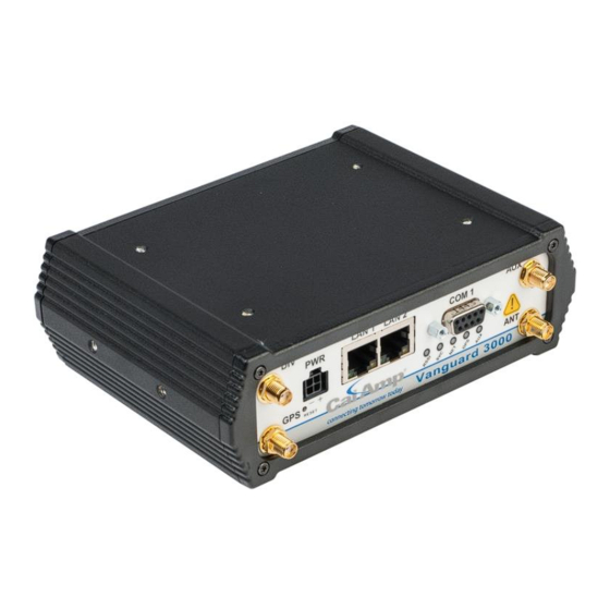
MECHANICAL SPECIFICATIONS The following table and figure show overall dimensions of the Vanguard router for fixed and mobile models. (Both models have the same dimensions and differ only slightly in appearance: the fixed model has only two antenna connectors in the front of the unit, where the mobile model has four.) Dimensioned drawings of units with mounting brackets are provided in 0. -
Page 12: Order Information
ORDER INFORMATION The following table shows the available order options and part numbers required for ordering Vanguard routers. Table 2: Vanguard Router Order Information Router Model Part Number Vanguard 3000 Fixed VG3000-PXS-F Vanguard 3000 Mobile VG3000-PXS-M 1.5.1 MOUNTING BRACKETS A mounting bracket is provided with each Vanguard 3000. The type of bracket provided is determined by the typical mounting method for each application. -
Page 13: Accessories
1.5.2 ACCESSORIES Table 4: Vanguard router Accessories Accessory Part Number / Description 401-7500-001 4" plastic “Rubber Duck” style Antenna L2ANT0003 3" Mag Mount Antenna 150-7001-005 110 VAC Input Power 401-7100-003 GPS SMA Mag-Mount Antenna 401-7100-004 Wi-Fi Mag-Mount Antenna 150-7001-002 22' DC Power Cable w/ inline fuse (Mobile models) 150-7500-004 6' DC 3-wire Power Cable (Fixed models) - Page 14 Accessory Part Number / Description L2CAB0006 7' Ethernet Cable 250-5800-410 DIN Rail Mount — kit includes DIN mounting plate assembly (with retainer spring and screw), four #6-32 × ¼-inch length cap screws and four #6 lock washers for fastening to bottom of Vanguard chassis. Vanguard 3000 Multicarrier Cellular Data Modem &...
-
Page 15: External Connectors
EXTERNAL CONNECTORS This section describes the external connectors for the Vanguard router. Figure 6 shows the front panel connections for standard fixed models. Figure 7 shows the front panel connections for Mobile models with GPS and Wi-Fi. Figure 8 shows the rear panel for all models. - Page 16 Table 5: External connectors Panel Connection Description Indicators COM 1 RS-232 / RS-485 Serial to IP conversion use Primary RF Antenna Cellular Diversity Antenna AUX (Figure 7) RP-SMA Wi-Fi antenna GPS (Figure 7) GPS Antenna LAN 1, LAN 2 RJ-45 Interface for Ethernet connection to devices USB Mini Available for diagnostic use.
-
Page 17: Antenna
ANTENNA Primary cellular antenna connections are SMA female connectors and must be used with antenna with SMA male connectors. When using a direct mount or rubber duck antenna, choose the antenna specific to your band requirements. Mounting options and cable lengths are user’s choice and application specific. The diversity antenna connector, labeled DIV, can be used for a Diversity antenna. -
Page 18: Reset Button
Table 8 provides the serial cable design information to integrate the Vanguard modem into your system. Table 9 gives the default RS-232 / RS-485 communication parameters. Table 8: Standard RS-232/RS-485 DE-9 Pinout RS-232 RS-485 Direction Signal Signal ← (Out) ←(Out) →(In) →(In) ←(Out) -
Page 19: Getting Started
GETTING STARTED PACKAGE CONTENTS Vanguard Router Power Cable 22 Pin I/O Cable Mounting bracket Quick-Start Guide DEVICE CONNECTIONS 1. (GSM users) Insert the SIM card into the spring-loaded SIM slot as shown. Figure 11: Insert SIM card into SIM slot 2. -
Page 20: Lan Configuration
Figure 12: Connect antenna to ANT connector, connect Ethernet cable to either LAN port, and connect power cable Fixed model Mobile model LAN CONFIGURATION The Vanguard router is configured via a Web-browser interface and contains a DHCP server which will automatically assign an IP address to your computer, however in some cases it may be necessary to change the network settings on your computer to accept the IP address assigned by the Vanguard. -
Page 21: Cellular Connections
Refer to Provisioning (CDMA only) to provision your modem for proper operation. VANGUARD WEB INTERFACE Figure 13: CalAmp Vanguard Cellular Broadband Router Web Interface banner Start your Web browser and enter 192.168.1.50 in the address bar. A Web Server Authentication window appears. - Page 22 Figure 16: Main Navigation Pane — Mobile (with GPS and Wi-Fi) Note: If the computer you are using has previously been used to set up another CalAmp router at that same IP address, you may need to delete browser history (specifically, Temporary Internet files) for the pages of the web interface to display correctly.
-
Page 23: Unit Status
UNIT STATUS The Unit Status is the first page displayed when navigating to the Vanguard 3000 modem Web interface and is the default page. Select Unit Status from the left navigation pane to return to this page. From this page, you can view Status, System information or access Basic Settings. -
Page 24: System Information
Settings > Network Time). System Up time Uptime in hours, minutes and seconds. Current Firmware Version Firmware version currently loaded. Please visit www.calamp.com for the latest updates. Modem Module Model Model of the cellular modem installed. Modem Module Version Firmware version of the cellular modem. -
Page 25: Connection Status
Primary DNS The Primary DNS server, as assigned by the cellular carrier, when WAN is UP. Secondary DNS The Secondary DNS server, as assigned by the cellular carrier, when WAN is UP. Connection Status The information displayed in this section will vary depending on the Service Type. The possible options are described below. -
Page 26: System
Channel Cell Site channel number at which the modem is connected and is useful for the carrier in the event of troubleshooting. Frequency Cellular frequency band the modem is using. All U.S. CDMA carriers use 800MHz and/or 1900MHz; GSM/UMTS carriers in other countries may use 850MHz/900MHz/1800MHz/1900MHZ GSM bands or 800MHz/850MHz/900MHz/1900MHZ/2100MHz bands. -
Page 27: Associated Stations
System Serial Number The router serial number is a unique ID assigned when the product was built. Board ID Unit motherboard identifier. Model Number Unit model number defining its capabilities and features. Hostname The name of the router provided by the operating system. ... -
Page 28: Basic Settings
Signal Signal strength of AP. Noise The noise level indicates the amount of background noise in the environment. RX Rate Rx Rate is the rate at which packets are received from router. TX Rate TX Rate is the rate at which packets are sent from router. 3.1.3 BASIC SETTINGS Figure 19: Unit Status —... -
Page 29: Cell Connection
Network Time The Vanguard 3000 is capable of maintaining the current time (UTC) by synchronizing itself with a Network Time Protocol (NTP) Server. You may specify a server domain name or IP address and how frequently the router should synchronize with the server. The router must have DNS access and a route to the internet to synchronize with the supplied default ntp.org server –... - Page 30 Figure 20: Cell Connection — Carrier Carrier Active Carrier Select which carrier, Primary or Secondary, and credentials to use for carrier connection. Select Automatic to have the modem choose a carrier based on conditions defined in the Automatic Carrier Switching section at the bottom of the page.
- Page 31 upon startup, and to attempt reconnection if the connection is lost. Select Disable to prevent the modem from automatically connecting upon startup. When disabled, a button will be displayed that can be used to manually connect or disconnect the wireless WAN service. ...
-
Page 32: Settings
RSSI falls below If the received signal strength for the primary carrier falls below this number, the modem will switch to the secondary carrier. Enter the RSSI level threshold for which if the primary carrier connection drops below, the system will attempt to switch to the secondary carrier. -
Page 33: Pin Settings
SIM Status The Current Status section displays the current status of the SIM (whether a SIM card is present, and if so whether it is valid) and PIN (whether a PIN has been entered and PIN security enabled). SIM Status (status text) SIM ACCEPTED displays when a valid SIM card is inserted properly in the modem. - Page 34 To not enable this feature (not have your PIN remembered), select No. Enter your PIN in the Current PIN field and click Save to make your selection take effect. Disable PIN (Enter Current PIN) Yes / No To disable PIN security, select Yes. To enable PIN security, select No.
-
Page 35: Dynamic Dns
Note: This section is displayed only for devices that are capable of automatic (OMA-DM) provisioning. Sprint supports OMA-DM. You may enable or disable the automatic provisioning, and save the your desired setting. If enabled and the device is not provisioned (activated), each time at power-on (only) the unit will attempt an auto-activation. -
Page 36: System Monitor
Username The username used when setting up the account. Used to login to the Dynamic DNS service. Password The password associated with the username account. Hostname The hostname identified to the Dynamic DNS service. For example, test.myserver.com. ... - Page 37 Secondary IP Address User may enter an accessible IP address or domain name that will respond to a ping command. This address will be used if the entered number of consecutive ping failures using the first address is reached. ...
-
Page 38: Lan Settings
3.2.5 OTHER SETTINGS Figure 26: Other Settings Special Address Filtering Some traffic is not tolerated over the public internet. This feature will add filters to prevent such traffic to go out the interface. (the following destination IP addresses will be discarded: 0.0.0.0/8, 192.0.0.0/24, 192.0.2.0/24, 198.51.100.0/24, 203.0.113.0/24, 192.168.0.0/16, 172.16.0.0/12, 10.0.0.0/8, 169.254.0.0/16, 224.0.0.0/4, 240.0.0.0/4). -
Page 39: Dhcp Configuration
Important: The LAN subnet must not overlap with the WLAN subnet defined in the Access Point tab of the WLAN page. LAN Masquerade When enabled, the Vanguard masquerades all Ethernet traffic to the LAN, making all WAN traffic appear as if it originated from the Vanguard 3000. -
Page 40: Wlan Settings
it is possible for the device to receive the same IP address after the lease time expires. The default is set to 86400 seconds (1 day). Sequential IP IP addresses are allocated sequentially from the start-end range when checked. Addresses are based on the device’s hashed MAC address when unchecked –... -
Page 41: Access Point
The channel to be used in the Access Point mode. The Auto option attempts to scan for the “least busy” channel (which may change over time). If the Vanguard does not select a channel after a short period of time, CalAmp recommends that a specific channel be chosen and saved. Table 11: Explanation of Wireless Mode options... - Page 42 Access Point Active SSID When Automatic is selected, a unique SSID will be provided. When Manual is selected, the user must configure the SSID. Automatic SSID The automatic SSID is a unique SSID based off of the MAC address and is used when Automatic is selected for the Active SSID.
-
Page 43: Client
DHCP Configuration DHCP Selecting "Enable" will configure this device to assign IP addresses to client devices taken from a pool specified by the values entered in "Start IP Address" and "End IP Address". Selecting "Disable" will turn off the DHCP server functionality for the Ethernet interface. -
Page 44: Associated Clients
Wireless Devices Wireless Mode The following table gives explanations of the Wireless Mode options. Table 12: Explanation of Wireless Mode options Mode Explanation Disable The WLAN interface is disabled. Access Point The WLAN interface operates in Access Point mode. Parameters can be set on the Access Point tab. Client The WLAN interface operates in Client mode. -
Page 45: Router
Enabled Select Enabled to activate a particular client. Authentication/Encryption Select the wireless encryption method. Extra fields may display depending on the selected type. Cipher Type of Ciphers used for encryption. Select CCMP (Counter Mode CBC-MAC Protocol) or TKIP (Temporal Key Integrity Protocol). -
Page 46: Port Forwards
Select Router from the left navigation pane to access the Port Forwards, DMZ, IP Filtering, MAC Filtering , Static Routes and ARP tabs. 3.5.1 PORT FORWARDS Port Forwarding is a technique for transmitting and receiving network traffic through a router that involves re-writing the destination IP addresses and optionally the TCP/UDP port numbers of IP packets as they pass through. -
Page 47: Dmz Support
LAN Port Number Sets the port number used when forwarding to the destination IP address. Port Forwarding Configuration Table This section contains Port forwarding entries added by user. Edit Click the Edit button to edit an existing filter. ... -
Page 48: Ip Filtering
3.5.3 IP FILTERING Figure 32: Router — IP Filtering Add Custom IP Filters You can define up to 20 IP filters. Each IP filter is identified by a unique number (from 1 to 20). Click Add to add the filter to the Custom IP Filters table. Once all filters have been added, click Save & Apply to save all changes. An IP packet goes through the filtering logic: 1) An IP packet is received on one of the interfaces and is destined to the Vanguard unit 2) An IP packet is sent by the Vanguard unit... - Page 49 Filter Number Each IP filter is identified by a unique number from 1 to 20. Use Add to create new rules; use Edit to update existing rules. Enabled Each IP filter can be independently enabled or disabled. Source IP Address The source IP Address or subnet that will satisfy this criteria.
- Page 50 An IP packet can TERMINATE inside the Vanguard unit. WAN to Vanguard: The IP packet is received from the WAN (cellular) interface and is destined to the Vanguard unit. LAN to Vanguard: The IP packet is received from the LAN interface and is destined to the Vanguard unit. WLAN to Vanguard: The IP packet is received from the Wi-Fi interface and is destined to the Vanguard unit.
-
Page 51: Mac Filtering
3.5.4 MAC FILTERING The MAC Filtering tab opens the MAC filtering configuration page. MAC filtering allows up to five device MAC addresses to be entered for the LAN, and WLAN if installed, interfaces. The specific MAC addresses can either be the only addresses allowed to access the device and network (whitelist) or can be blocked from the device and network, allowing all other addresses through (blacklist). - Page 52 Select the Static Routes tab to open the routing configuration page. Static route tables may be created in this page and appear at the bottom. Static Routing refers to a manual method used to set up routing between networks. Figure 34: Router — Static Routes Static Routes ...
-
Page 53: Arp
3.5.6 ARP Clicking Router > ARP displays the Address Resolution Protocol (ARP) table, which shows IP addresses, the corresponding MAC address on the physical layer, and the interface known to the Vanguard router. Figure 35: Router — ARP IPv4-Address IP Address of the device on one of the local interfaces (LAN or WLAN) with the specified MAC Address. - Page 54 3.5.7 IP PASSTHROUGH IP Passthrough will allow user to configure IP Passthrough on Vanguard router. Figure 36: IP Passthrough GLOBAL CONFIGURATION IP Passthrough (IPP) Mode: Select "Enabled" when you want the IP address of WAN to be assigned to single Ethernet device. Most of the routing mode services- Port Forwarding, DMZ, IP-Filter, MAC-Filter, Static Routes;...
- Page 55 Notes: Change in router mode from IP Passthrough to non-IP Passthrough or vice versa is Service Affecting and causes the IMMEDIATE Reboot of the device. Configuration change in IP Passthrough mode will not be carried over when the router mode is switched back to non-IP Passthrough mode. Change in Automatic Subnet value will take effect in the next IP allocation on WAN.
-
Page 56: Security
Radius Client: Enabling this service will allow Vanguard to perform Radius Authentication for Vanguard login in IPP mode for configured radius server and port. ICMP Ping: Enabling this service will allow incoming and outgoing ICMP traffic to redirect from/to Vanguard to/from WAN for all destination/source. - Page 57 PPTP Client Status Indicates the status of the PPTP Client interface, usually UP when connected properly. PPTP is the Point-to- Point Tunneling Protocol used to implement a Virtual Private Network (VPN). IP Address The current IP address assigned to the modem by the VPN server. ...
-
Page 58: Pptp
3.6.2 PPTP The Point-to-Point Tunneling Protocol (PPTP) is a method for implementing virtual private networks (VPN). Figure 38: Security — PPTP PPTP Client Configuration PPTP Client Selecting Enable will allow the PPTP functionality. Selecting Disable will shut off PPTP functionality. ... -
Page 59: Ipsec
PTPP Server Configuration PPTP Server Selecting Enable starts the VPN server, and selecting Disable stops it. Server Local IP The IP address that clients will use to communicate with the server after they connect. Client IP Range The pool of IP addresses assigned to clients. -
Page 60: Ipsec Configuration
Figure 39: Security — IPsec IPSec Configuration IPsec All IPsec functionality can be Enabled/Disabled with this control. Drop Filters This setting controls how packets for the Remote Subnet(s) are handled when an enabled tunnel is down. When Enabled, packets that would normally go through the tunnel are discarded when the tunnel is down. When Disabled, packets are routed through the appropriate interface. - Page 61 an existing tunnel (these are displayed in the Tunnel Configuration Table), click the Edit button to the right of the table entry and the saved values are displayed for editing. Enabled Check Enable to enable a tunnel. Server IP Address The public IP address of the remote IPsec server or the firewall in front of the IPsec server.
-
Page 62: Gre
Phase 2 Proposal Select an entry from the Proposal table. Tunnel Configuration Table Edit Click the Edit button to edit the properties of a tunnel. Delete Click the Delete button to delete the tunnel . Proposals The Phase 1 and Phase 2 Encryption, Authentication, DH Group and Life Time parameters can be changed from this section. -
Page 63: Openvpn
Local IP Address The local (normally WAN interface) IP address associated with the tunnel. Remote IP Address The remote IP address associated with the tunnel. Tunnel IP Address & Mask The IP address assigned to the tunnel interface. [ Example: 192.168.10.100 ] ... - Page 64 Operation Mode This parameter tells the device to operate in client mode This feature applies only to tunnels that are enabled. Tunnel Configuration Name The tunnel name. This must be a unique name (do not use space) to identify the tunnel and must be provided to create a tunnel.
-
Page 65: Security Management
Hashing Function This option is used to specify the hashing (authentication) to be used for data communication within the tunnel. Security Selection This option specifies certificate selection to be used. Log Level Specifies the log verbosity. Tunnel Configuration Table The list of OpenVPN tunnels. -
Page 66: Serial
SERIAL From the main navigation pane, select Serial for access to the external serial port configuration page. 3.7.1 EXTERNAL SERIAL Use the External Serial tab to define and configure the functioning of the RS-232 / RS-485 Serial Port, which can be set to function as a Packet Assembler and Disassembler (PAD), transferring all serial data to or from a specified UDP/TCP port, or to output GPS position reports. -
Page 67: Serial Port Configuration
Serial Port Configuration Electrical Interface Sets the serial port to use either RS-232 or RS-485. RS-485 is a balanced electrical interface suited for multi- drop applications, such as communication over long cable distances or in noisy environments. When RS-485 is selected, the Flow Control option becomes unavailable. -
Page 68: Gps/Gnss
Remote (AAVL): Select this to have the Remote report sent out the serial port. The report rate is based on the AAVL settings. External PAD Configuration The mode selection configures the service to listen on configured TCP or UDP port or connect to an external host as a TCP client. -
Page 69: Status
GPS LED Color / State Meaning Position lost; reporting from last known position. Flashing Red Position lost for more than 2 minutes. 3.8.1 STATUS This section displays the current status of the GPS receiver. Figure 43: GPS/GNSS —Status Status Condition Indicates the quality of received GPS reports. -
Page 70: Settings
3.8.2 SETTINGS Figure 44: GPS — Settings GPS Settings GPS Streaming Select Enable to start the GPS engine, Disable to stop it Differential Correction Differential Correction allows WAAS correction information to be used to improve accuracy of the GPS position reports. - Page 71 Report Rate For applications that require it, GPS reports are normally received from the internal GPS receiver at a rate of once per second. Local Delivery reports are sent at this rate. Remote Delivery reports are limited by the “But no less than X seconds between reports”...
- Page 72 Format Definition Example NMEA, VTG NMEA VTG (Vector $GPVTG,,T,,M,0.004,N,0.008,K,A*2F Track and speed over Ground) NMEA, ZDA Time and Date $GPZDA,181855.00,21,04,2015,00,00*67 GPS “sentences” are collected the from embedded GPS receiver in the Vanguard Cellular Broadband Router. These sentences are converted into the above formats and are provided to both local and remote delivery services. Each report from the TCP ports is terminated with carriage-return/linefeed characters (CRLF).
- Page 73 Host Port Number (1024-65535) Specify the local port for the TCP server or the remote port for the UDP client. Report every ( ) seconds Triggers the sending of a new remote report if the time since the last remote report exceeds the specified number of seconds.
-
Page 74: Diagnostics
NMEA Sentences This section displays all NMEA Sentence Lists currently present. You can add a new NMEA Sentence List by entering a unique name, and then clicking the Add button. DIAGNOSTICS From the main navigation pane, select Diagnostics for access to the SMS, RSSI Traps and Logging configuration pages. 3.9.1 SMS The SMS CLI (Command-Line Interface) allows a small set of commands to be sent to the Vanguard 3000 using SMS. - Page 75 /iostatus pw=[password] Returns the following fields: D1=, D2= the state of the two digital inputs: 0 (inactive) or 1 (active) A1=, A2= the levels of the two analog inputs, in volts R1=, R2= the state of the two digital (historically called “relay”) outputs: 0 (ground) or 1 (open) /pptpstart pw=[password] Starts the PPTP VPN.
-
Page 76: Rssi Traps
including the country code prefix. Select the button for a Sender (1-3), and then enter the address in the adjacent field. If all three addresses are disabled, then commands will be accepted from ALL senders. Respond only to Senders For security, command responses, including error messages, can be restricted to be returned only to the registered Sender SMS addresses. -
Page 77: Syslog Settings
High Threshold Send an SNMP Notification message when the average RSSI rises above this value. Average RSSI across The number of samples, taken 10 seconds apart, used to compute the average RSSI. 3.9.3 SYSLOG SETTINGS Figure 47: Diagnostics — Syslog Settings Syslog Configuration ... -
Page 78: System Log
The System Log page provides a way to capture the current status log of the modem. Log information is useful when contacting CalAmp Technical Support to resolve operational problems. The Download… button provides a convenient way to save the log to the local PC. -
Page 79: Kernel Log
3.9.5 KERNEL LOG The Kernel Log page provides a way to capture the kernel log of the modem. The Download… button provides a convenient way to save the log to the local PC. Figure 49: Diagnostics — Kernel Log 3.10 I/O SETTINGS 3.10.1 STATUS Figure 50: I/O Settings —... - Page 80 Modem Temperature Displays temperature of the Wireless Modem, in Celsius. Analog Input Status Analog Input 1 & 2 Displays voltage of the specified analog input, in Volts. Digital Input Status Ignition, Input 1 and Input 2 Displays the status of the specified input: Active (high state) or Normal (low state). Digital Output Status ...
-
Page 81: Snmp
3.10.2 SNMP The Simple Network Management Protocol (SNMP) is used in network management systems to monitor network- attached devices for conditions that warrant administrative attention. SNMP version v2c and v3 are supported with the exception of INFORM. Figure 51: I/O Settings — SNMP SNMP Configuration ... - Page 82 SNMP v3 User Name The user name for secure access to the Management Information Bases (MIBs) observing v3 standard. Authentication Select the method for encoding the Authentication Password for accessing the Management Information Bases (MIBs) – None, MD5 or SHA. ...
-
Page 83: Settings
3.10.3 SETTINGS Status Monitoring is provided via NMEA-based protocol. The Vanguard 3000 I/O subsystem operates according to a manager/agent model. The PC-hosted manager sends requests to the Vanguard 3000 I/O agent, which performs the required actions. The Vanguard agent reports alarms to the PC-hosted manager. More information about the Vanguard 3000 —... -
Page 84: Digital Output
NMEA Connection Manager IP Address/Port The IP address and service port of the NMEA server (manager). Manager Connection Type The connection protocol to communicate with the NMEA server (manager). NMEA Identification Unit ID The Unit Name to be included in the NMEA message payload. ... -
Page 85: Labels
Digital Input Ignition, Digital Input 1, Digital Input 2 Enable or disable NMEA alarm and notification when the input state changes. 3.10.4 LABELS Each diagnostic value can be user-defined messages indicating its normal and abnormal conditions. I/O Labels can up to 64 characters long and can consist of letters, digits, space and the characters #%().=+-_$:;/? Figure 53: I/O Settings —... -
Page 86: Admin
Changes the administrator password for accessing the device via the Web Interface. The password can be up to 32 characters long and can consist of any printable character except '&"<> IMPORTANT NOTE. CalAmp strongly recommends that the default password be changed before the Vanguard is deployed on a public cellular network. - Page 87 SSH Access Listening Port The SSH server’s port number on the LAN side of the Vanguard. The WAN side port number is changed in Admin > Remote Admin. Password Authentication When the Allow SSH password authentication checkbox is selected, the device will allow the SSH clients to login using a password.
-
Page 88: Remote Server App
3.11.2 REMOTE SERVER APP The Remote/Cloud Server Applications config page can be used to configure the built-in CalAmp Remote/Cloud Server and Client applications. The Client is built in the unit, and can be enabled/disabled. The Remote/Cloud Primary Server is used for event reporting and can be empty if there's no event reporting server. -
Page 89: Remote Admin
Maintenance Server Server Address This is the domain name or IP address of the Maintenance Server. The Client running in the unit uses this address to perform ID report to the server, and unit firmware upgrade and configuration update from the server. -
Page 90: Radius
Enable HTTPS Enable remote administration via the secure web server. Enable SSH Enable remote administration via Secure Shell. Enable CLI Enable remote administration via CLI. Enable SNMP Enable remote administration via the Simple Network Management Protocol. ... -
Page 91: Firmware Update
When newer versions of the modem firmware become available, the user can download the proper file from the CalAmp web site and manually update the unit by uploading the new firmware. Time required for uploading new firmware, depending on the unit, may range from four to fifteen minutes. - Page 92 Firmware / Configuration Import This section allows the user to upgrade to new firmware, import previously exported configurations and load ODP applications and PEG scripts. Imports can be done over the local Ethernet connection or over the cellular network if Remote Administration is enabled, allowing remote access to the Vanguard 3000 Web Interface and the Firmware Update page.
-
Page 93: System Reset
3.11.6 SYSTEM RESET Figure 59: Admin — System Reset Click the Reboot… button to reset the system. It takes approximately 30 seconds for the system to come back online. IP ADDRESSING OVERVIEW When Vanguard cellular router is connected to a cellular carrier, it will always have at least two IP addresses. The first is the local area network (LAN) address. -
Page 94: Private Versus Public Ip Addresses
Ethernet Subnet Mask 255.255.255.0 Network ID 192.168.1.0 (reserved – first IP address in subnet) Broadcast Address 192.168.1.255 (reserved – last IP address in subnet) Vanguard 3000 192.168.1.50/24 PLC/RTU #1 192.168.1.10/24 Computer #1 192.168.1.125/24 By changing the subnet mask, the network can be made to include as many or as few IP addresses as desired. Ethernet devices can only talk directly to other devices that have IP addresses within the same IP subnet. -
Page 95: Dmz
192.168.1.250. The Vanguard then modifies the destination IP address and port number before forwarding the packet onto the local area network. Figure 60: Port Forwarding Example Port forwarding is useful for field applications that use polling that is initiated by a polling master. The port forwarding function allows the polling master to establish a data connection through the Internet. -
Page 96: Ipsec And Vpn Pass-Through Deployment Guide
IPSEC AND VPN PASS-THROUGH DEPLOYMENT GUIDE This chapter will help anyone who wants to build a secure IP network using IPsec and the CalAmp Vanguard 3000 Cellular Modem. Case #1: Vanguard Configured IPsec Client will demonstrate the Vanguard 3000 when used as an IPsec client. -
Page 97: Case #1: Vanguard Configured Ipsec Client
5.2.1 CASE #1: VANGUARD CONFIGURED IPSEC CLIENT Overview IPsec is a security protocol that provides secured communication tunnels over IP. As you create IPsec tunnels through the Vanguard 3000 Web interface in the Security » IPsec tab, they will be displayed in the Tunnel Table at the bottom of the IPsec tab. - Page 98 VPN Server IP Address (Remote ID) 10.168.86.192 10.168.86.192 Remote Subnet 192.32.8.254/32 10.0.198.198/32 Phase1 Encryption 3DES/MD5/Group2 3DES/MD5/Group2 Phase 2 Encryption details 3DES/MD5 3DES/MD5 Pre-Shared Key (PSK) Password1! Secret2! Perfect Forward Security (PFS) Disabled Disabled Dead Peer Detection delay timeout...
- Page 99 Step 4 Select a name for the IPsec tunnel and enable it by checking the Enable box. Figure 63: IPsec Configuration Page Step 5 IPsec tunnel configuration information for the tunnels. Select a tunnel to configure by entering its name in the Name field.
- Page 100 002 "ttunnel1" #1: transition from state STATE_MAIN_I3 to state STATE_MAIN_I4 004 "ttunnel1" #1: STATE_MAIN_I4: ISAKMP SA established {auth=OAKLEY_PRESHARED_KEY cipher=oakley_3des_cbc_192 prf=oakley_md5 group=modp1024} 002 "ttunnel1" #1: Dead Peer Detection (RFC 3706): enabled 002 "ttunnel1" #2: initiating Quick Mode PSK+ENCRYPT+TUNNEL+UP+IKEv2ALLOW {using isakmp#1 msgid:4328edc8 proposal=3DES(3)_192-MD5(1)_128 pfsgroup=no-pfs} 117 "ttunnel1"...
-
Page 101: Case #2 Vanguard Configured To Use A Dmz For Vpn Pass-Through
5.2.2 CASE #2 VANGUARD CONFIGURED TO USE A DMZ FOR VPN PASS-THROUGH Figure 64 Vanguard configured with a DMZ for VPN Pass-Through Vanguard – VPN Pass-Through Configuration Example Using a DMZ In this scenario, the Vanguard is configured to use a DMZ to facilitate pass-through for the VPN connection. Apply these parameter changes into the Vanguard. -
Page 102: User I/O Port
USER I/O PORT The Vanguard has a 22 pin connector on the back panel that can be used for general purpose analog and digital inputs. Figure 65: User I/O port connector Table 19: User I/O Port connector pin out Signal Notes number Name... -
Page 103: Electrical Characteristics
ELECTRICAL CHARACTERISTICS Table 20: External connectors Symbol Parameter Units Digital Inputs Digital Voltage Recommended Input Range 30.0 Positive Threshold Voltage for Digital Inputs Negative Threshold Voltage for Digital Inputs Hysteresis Voltage for Digital Inputs 0.07 Analog Inputs Analog Voltage Recommended Input Range 30.0 Accuracy ADC accuracy... -
Page 104: Input Circuit For Analog Inputs
INPUT CIRCUIT FOR ANALOG INPUTS SIMPLIFIED CIRCUIT FOR DIGITAL INPUT SIMPLIFIED CIRCUIT FOR OPEN COLLECTER OUTPUTS Vanguard 3000 Multicarrier Cellular Data Modem & IP Router PN 134732-VG3000 Rev. D| Page 97... -
Page 105: Appendix A - Abbreviations And Definitions
APPENDIX A — ABBREVIATIONS AND DEFINITIONS AAVL: Autonomous Automatic Vehicle Location HSDPA: High-Speed Downlink Packet Access ADC: Analog to Digital Converter HSUPA: High-Speed Uplink Packet Access APN: Access Point Name IC: Industry Canada CDMA: Code Division Multiple Access IMEI: International Mobile Equipment Identity CHAP: Challenge Handshake Authentication Protocol IMSI: International Mobile Subscriber Identity CSD: Circuit-Switched Data... - Page 106 PCS: Personal Communications Service SIM: Subscriber Identity Module PDP: Packet Data Protocol SMA: SubMiniature version A (connector) PDU: Protocol Data Unit SMS: Short Message Service PIN: Personal Identification Number TAIP: Trimble ASCII Interface Protocol PPP: Point-to-Point Protocol TCP/IP: Transmission Control Protocol / Internet Protocol PPTP: Point-to-Point Tunneling Protocol TNC connector: Threaded Neill-Concelman connector...
-
Page 107: Appendix B - Mechanical Specifications
APPENDIX B — MECHANICAL SPECIFICATIONS Following figures show Vanguard 3000 standard and mobile models. Dimensions are shown for the unit alone and with mounting brackets that allow them to be secured to any surface that can be drilled for this purpose. The drawings may be used for layout reference, but it is advised that a physical comparison be made to the modem and bracket before laying out and drilling mounting holes. - Page 108 Table 22 Overall Dimensions, Vanguard 3000 with mounting plate Figure 67 Vanguard 3000 with mounting plate overall dimensions Dimension Inches Centimeters Height 1.91 4,88 Width 6.00 15,2 Depth 6.45 13,84 Base plate mounting hole location detail ø 0.176 in. (0,447 cm) – 4 thru holes for securing base plate to a surface suitable for mounting top or bottom.
- Page 109 Figure 68 Vanguard 3000 with DIN rail mount overall dimensions Table 23 Overall Dimensions, Vanguard 3000 with DIN rail mount Dimension Inches Centimeters Height 2.20 5,92 Width 6.00 15,2 Depth 4.50 ± 0.04 11,2 ± 0,1 Depth 4.28 10,9 DIN rail mount attaches to underside of unit as shown. (Chassis only) Table 24 Overall Dimensions, Vanguard 3000 with mobile...
- Page 110 Figure 70 Vanguard 3000 with mobile mounting bracket for top surface mounting Figure 71 Mobile mounting bracket slot dimension detail Vanguard 3000 Multicarrier Cellular Data Modem & IP Router PN 134732-VG3000 Rev. D| Page 103...
-
Page 111: Appendix C - Ul Installation Instructions
APPENDIX C — UL INSTALLATION INSTRUCTIONS UL acceptance requires the following installation instructions. These installation instructions are available and may be downloaded from the www.calamp.com website listed on the Quick Start Guide with each unit and include the following: This equipment is suitable for use in Class I, Division 2, Groups A, B, C and D or non-hazardous locations only. - Page 112 Accessory Part Number / Description Quantity 401-7100-004 Wi-Fi Mag-Mount Antenna 150-7001-002 22' DC Power Cable (Mobile models) 150-7500-004 6' DC 3-wire Power Cable (Fixed models) L2CAB0006 7' Ethernet Cable Vanguard 3000 Multicarrier Cellular Data Modem & IP Router PN 134732-VG3000 Rev. D| Page 105...
-
Page 113: Appendix D - Nmea I/O Agent
APPENDIX D — NMEA I/O AGENT As described in section 3.10 I/O Settings of this User Manual, the Vanguard 3000 router supports the following I/Os: Vanguard 3000 Input Status: Ignition Sense, Main Voltage Indication and Modem Temperature. Two general-purpose external analog input lines. ... - Page 114 The manager is able to send I/O responses, alarms, and indications to a manager IP address via: (a) TCP (connection initiated by the Vanguard 3000). (b) UDP A single operator-configurable transport service (UDP or TCP) is available at any moment and is used for both directions (manager →...
- Page 115 Receive an indication generated by the Vanguard 3000 (1) Vanguard 3000 sends indication (NMEA msg: ALR) [manager application] <-------- alarm -----(1)---- [Vanguard 3000] Alarms and Indications Alarms Alarms are abnormal conditions or faults declared by the Vanguard 3000. The manager is able to acknowledge alarms to stop their repeated generation. Reporting Alarms are reported continually at GPS AVL reporting rate until acknowledged by the manager or until the alarm root cause disappears.
-
Page 116: Pdu Types
$IIALR ... $IIALR ... $IIALR ... $GPMRC ... $GPVTG PDU TYPES Note: In all the examples provided below, for clarity the checksum is replaced by the value “FF.” ACK Message I/O value read request (manager --> Vanguard 3000) Output line setting request (manager -->... - Page 117 DO2 (COM1/NO1) Reserved for Future use NMEA-compliant checksum Example: Acknowledge a “Cell module temperature out of range” alarm $IIACK,011,*FF<CR><LF> Response to I/O read request (manager <-- Vanguard 3000) Response to output line state setting request (manager <-- Vanguard 3000) $IIXDR,t,x.x,u,ioid;ip*hh <CR><LF>...
- Page 118 AIN1 AIN2 Reserved for future use Operator-specified IP address NMEA-compliant checksum Example: Reports a temperature of 42.1 (in degrees Celsius) for the Cell module $IIXDR,C,42.1,C,11;172.20.41.9*FF<CR><LF> As per NMEA 0183, the <u> field is left empty for digital I/Os, including ignition sense (switches and valves, <t> field value: S).
-
Page 119: Appendix Eservice And Support And Warranty Statement
Product Warranty, RMA, and Contact Information CalAmp guarantees that every Vanguard 3000 Modem will be free from physical defects in material and workmanship for three (3) years from the date of purchase when used within the limits set forth in the specifications section of this manual. - Page 120 RETURN REQUESTS WILL NOT BE PROCESSED WITHOUT THIS INFORMATION. For units in warranty, customers are responsible for shipping charges to CalAmp. For units returned out of warranty, customers are responsible for all shipping charges. Return shipping instructions are the responsibility of the customer.
-
Page 121: Warranty Statement
("Products") are free from defects in material and workmanship and will conform to published technical specifications for a period of, except as noted below, three (3) year from the date of shipment to Buyer. CalAmp makes no warranty with respect to any equipment not manufactured by CalAmp, and any such equipment shall carry the original equipment manufacturer's warranty only. - Page 122 ABOUT CALAMP CalAmp (NASDAQ: CAMP) is a proven leader in providing wireless communications solutions to a broad array of vertical market applications and customers. CalAmp's extensive portfolio of intelligent communications devices, robust and scalable cloud service platform, and targeted software applications streamline otherwise complex Machine-to-Machine (M2M) deployments.
Need help?
Do you have a question about the Vanguard 3000 VG3000-PXS-F and is the answer not in the manual?
Questions and answers