Sign In
Upload
Download
Table of Contents
Contents
Add to my manuals
Delete from my manuals
Share
URL of this page:
HTML Link:
Bookmark this page
Add
Manual will be automatically added to "My Manuals"
Print this page
×
Bookmark added
×
Added to my manuals
Manuals
Brands
CalAmp Manuals
Network Router
Guardian-100
User manual
CalAmp Guardian-100 User Manual
Narrowband ip router
Hide thumbs
1
2
3
4
5
6
Table Of Contents
7
8
9
10
11
12
13
14
15
16
17
18
19
20
21
22
23
24
25
26
27
28
29
30
31
32
33
34
35
36
37
38
39
40
41
42
43
44
45
46
47
48
49
50
51
52
53
54
55
56
57
page
of
57
Go
/
57
Contents
Table of Contents
Bookmarks
Table of Contents
Table of Contents
1 Guardian Overview
General Description
Operational Characteristics
Physical Description
Front Panelthe Front Panel Has the Following Connections
The Front Panel Has the Following Connections
LED Panel
User Interface Port
SETUP and COM Ports
Power Connector
Antenna Connector
Chassis Dimensions
Part Numbers and Availability
Guardian Radio
Accessories and Options
Product Warranty
RMA Request
Documentation and Downloads
2 System Architecture and Network Planning
Single Coverage Area
Network Architecture
Point-To-Point
Point-To-Multipoint
Multiple Point-To-Point
Peer-To-Peer
Store and Forward
Network Using a T-Base
Network Using a T-Base Repeater
Network Using a Guardian for Online Diagnostics
Extending the Coverage Area with a Relay Point
Understanding RF Path Requirements
Site Selection and Site Survey
Site Selection
Site Survey
Selecting Antenna and Feedline
Antenna Gain
Omni Directional Antenna
Yagi Antenna
Vertical Dipoles
Feedline
RF Exposure Compliance Requirements
Terrain and Signal Strength
Radio Interference
3 Setup and Configuration
Install the Antenna
Measure and Connect Primary Power
Connect Guardian to Programming PC
Guardian Field Programming Software
4 Unit Status
Unit Identification and Status
Diagnostics
Online Diagnostics
Offline Diagnostics
Remote Commands
5 Using Guardian Software
Port Statistics
Data Type
Guardian Specifications
Product Warranty
Advertisement
Quick Links
1
General Description
2
User Interface Port
3
Power Connector
4
Setup and Com Ports
5
Guardian Field Programming Software
Download this manual
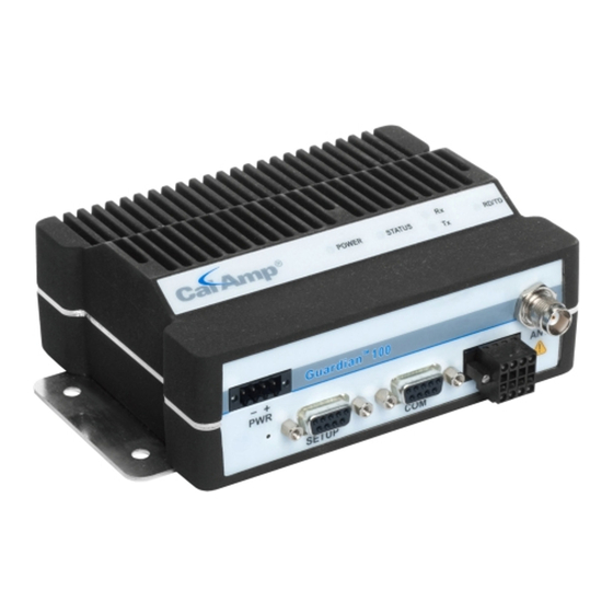
Guardian-100™
Guardian-200™
Guardian-400™
Guardian-900™
Narrowband IP Router
User Manual
PN 001-5008-000 Rev 8E Preliminary ETSI Version
Revised May 27, 2010
Table of
Contents
Previous
Page
Next
Page
1
2
3
4
5
Advertisement
Table of Contents
Need help?
Do you have a question about the Guardian-100 and is the answer not in the manual?
Ask a question
Questions and answers
Related Manuals for CalAmp Guardian-100
Network Router CalAmp Guardian-400 User Manual
Narrowband ip router (57 pages)
Network Router CalAmp Viper 100 User Manual
Viper sc series; viper sc+ series ip router for licensed spectrum (115 pages)
Network Router CalAmp Vanguard 3000 User Manual
Multicarrier 3g cellular broadband router (138 pages)
Network Router CalAmp LMU-5541 Hardware And Installation Manual
(29 pages)
Network Router CalAmp Fusion Quick Start Manual
High-performance multi-band lte router (2 pages)
Network Router CalAmp Viper SC+ Quick Start Manual
Intelligent ip router for licensed spectrum (3 pages)
Network Router CalAmp Vanguard 3000 Quick Start Manual
Multicarrier 3g cellular broadband router (2 pages)
Network Router CalAmp Vanguard 3000 VG3000-PXS-F User Manual
Vanguard 3000 series multicarrier 3g cellular broadband router (122 pages)
Network Router CalAmp Fusion LTE User Manual
(79 pages)
Network Router CalAmp Fusion User Manual
High-performance multi-band lte router (123 pages)
Network Router CalAmp Dataradio Sentry 4G 900 User Manual
900 mhz 802.16-2005 subscriber station broadband router (49 pages)
This manual is also suitable for:
Guardian-200
Guardian-400
Guardian-900
Table of Contents
Save PDF
Print
Rename the bookmark
Delete bookmark?
Delete from my manuals?
Login
Sign In
OR
Sign in with Facebook
Sign in with Google
Upload manual
Upload from disk
Upload from URL


Need help?
Do you have a question about the Guardian-100 and is the answer not in the manual?
Questions and answers