Sign In
Upload
Download
Table of Contents
Contents
Add to my manuals
Delete from my manuals
Share
URL of this page:
HTML Link:
Bookmark this page
Add
Manual will be automatically added to "My Manuals"
Print this page
×
Bookmark added
×
Added to my manuals
Manuals
Brands
CalAmp Manuals
Network Router
Viper 100
User manual
CalAmp Viper 100 User Manual
Viper sc series; viper sc+ series ip router for licensed spectrum
Hide thumbs
1
2
3
4
Table Of Contents
5
6
7
8
9
10
11
12
13
14
15
16
17
18
19
20
21
22
23
24
25
26
27
28
29
30
31
32
33
34
35
36
37
38
39
40
41
42
43
44
45
46
47
48
49
50
51
52
53
54
55
56
57
58
59
60
61
62
63
64
65
66
67
68
69
70
71
72
73
74
75
76
77
78
79
80
81
82
83
84
85
86
87
88
89
90
91
92
93
94
95
96
97
98
99
100
101
102
103
104
105
106
107
108
109
110
111
112
113
114
115
page
of
115
Go
/
115
Contents
Table of Contents
Bookmarks
Table of Contents
Copyright Notice
Important Notice
Table of Contents
1 Product Overview
General Description
Operational Characteristics
Physical Description
Chassis Dimensions
LED Panel
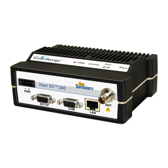
Front Panel
Product Warranty
Models and Availability
2 Network Architecture and System Planning
Network Architecture
Point-To-Point
Point-To-Multipoint
Report by Exception
Extending the Coverage Area with a Relay Point
IP Forwarding Modes
Bridge Mode
Router Mode
Multispeed Networking
System Planning
Understanding RF Path Requirements
Terrain and Signal Strength
Radio Interference
Selecting Antenna and Feedline
3 Quickstart
PC LAN Setup
Install the Antenna
Measure and Connect Primary Power
Connect Viper SC to Programming PC
Configure Your Viper
Initial Installation Login
Setup Wizard
4 Web Interface
Unit Status
General
Diagnostics
Setup Wizard
Basic Setup
General
IP Settings
Channel Table
Serial Ports
Setup (Advanced)
RF Optimizations/Mac Advanced Settings
IP Services
IP Addressing
IP Optimization
IP Routing
Time Source
Alarm Reporting/Diagnostic Settings
User Settings
Security
Password and Encryption
Radius
Vpn
Statistics
Ethernet Interface
Serial Interface
RF Interface
Maintenance
Ping Test
Config Control
Package Control
Net Tests
RF Tests
Wing Commander
Feature Options
Network Management/Neighbor Table
Neighbor Discovery
Status
Maintenance
5 Network Optimization
Maximizing TCP/IP Throughput
Maximizing Throughput with a Weak RF Link
Use Router Mode with RF Acknowledgements Enabled
Reduce RF Network Bit Rate
Increase OIP and MAC Retries Limit
6 Upgrading Your Firmware
Upgrade Procedure (Modem)
Upgrade Procedure (Radio)
Verify File Integrity
Appendix A - Specifications
Appendix B - Regulatory Certifications
Appendix C - Product Warranty
Appendix D - Definitions
Advertisement
Quick Links
1
General Description
2
Operational Characteristics
3
Led Panel
4
Appendix A - Specifications
Download this manual
VIPER SC™ VIPER SC+™
IP ROUTER FOR LICENSED SPECTRUM
User Manual
PN 001-5008-000 Rev 11
Revised August 2011
Table of
Contents
Previous
Page
Next
Page
1
2
3
4
5
Advertisement
Table of Contents
Need help?
Do you have a question about the Viper 100 and is the answer not in the manual?
Ask a question
Questions and answers
Related Manuals for CalAmp Viper 100
Network Router CalAmp Viper 900 User Manual
Viper sc series; viper sc+ series ip router for licensed spectrum (115 pages)
Network Router CalAmp Viper 400 User Manual
Viper sc series; viper sc+ series ip router for licensed spectrum (115 pages)
Network Router CalAmp Viper SC+ Quick Start Manual
Intelligent ip router for licensed spectrum (3 pages)
Network Router CalAmp LMU-5541 Hardware And Installation Manual
(29 pages)
Network Router CalAmp Guardian-100 User Manual
Narrowband ip router (57 pages)
Network Router CalAmp Fusion Quick Start Manual
High-performance multi-band lte router (2 pages)
Network Router CalAmp Vanguard 3000 User Manual
Multicarrier 3g cellular broadband router (138 pages)
Network Router CalAmp Vanguard 3000 Quick Start Manual
Multicarrier 3g cellular broadband router (2 pages)
Network Router CalAmp Vanguard 3000 VG3000-PXS-F User Manual
Vanguard 3000 series multicarrier 3g cellular broadband router (122 pages)
Network Router CalAmp Fusion LTE User Manual
(79 pages)
Network Router CalAmp Fusion User Manual
High-performance multi-band lte router (123 pages)
Network Router CalAmp Dataradio Sentry 4G 900 User Manual
900 mhz 802.16-2005 subscriber station broadband router (49 pages)
This manual is also suitable for:
Viper 900
Viper 400
Viper sc 100
Viper sc 200
Viper sc 400
Viper sc+ 900
Table of Contents
Print
Rename the bookmark
Delete bookmark?
Delete from my manuals?
Login
Sign In
OR
Sign in with Facebook
Sign in with Google
Upload manual
Upload from disk
Upload from URL


Need help?
Do you have a question about the Viper 100 and is the answer not in the manual?
Questions and answers