Table of Contents
Advertisement
Quick Links
Advertisement
Table of Contents

Related Manuals for Supermicro SuperStorage Server 6048R-E1CR90L


Summary of Contents for Supermicro SuperStorage Server 6048R-E1CR90L
- Page 1 6048R-E1CR90L UpER toRAgE ERvER USER’S MANUAL Revision 1.0...
- Page 2 State of California, USA. The State of California, County of Santa Clara shall be the exclusive venue for the resolution of any such disputes. Supermicro's total liability for all claims will not exceed the price paid for the hardware product.
-
Page 3: About This Manual
This document lists compatible parts available when this document was published. Refer to the Supermicor web site for updates on supported parts and configurations. This manual may be periodically updated without notice. Please check the Supermicro Web site for possible updates.(http://www.supermicro.com). -
Page 4: Table Of Contents
SuperStorage Server 6048R-E1CR90L User's Manual Contents Chapter 1 Introduction 1.1 Overview ..........................8 1.2 Unpacking the System ......................8 1.3 System Features ........................9 1.4 Chassis Views ........................10 Control Panel ........................10 Chassis Front ........................11 Chassis Rear ........................12 Chassis Top ........................13 1.5 Motherboard Layout ......................14 Motherboard Jumpers, Connectors, and Indicators ............14... - Page 5 Preface 2.4 Assembling the Cable Management Arm .................27 Swing Arm Functionality of the Cable Arm ...............30 Chapter 3 Maintenance and Component Installation 3.1 Removing Power ........................31 3.2 Accessing the System ......................32 3.3 Motherboard Components ....................34 Processor and Heatsink Installation ..................34 Memory Installation ......................38 Memory Support ......................38 DIMM Module Population Configuration ................38...
- Page 6 SuperStorage Server 6048R-E1CR90L User's Manual 4.5 LED Indicators ........................65 4.6 SATA Connections ......................67 Chapter 5 Software 5.1 OS Installation ........................68 Installing the Windows OS for a RAID System ..............68 Installing Windows to a Non-RAID System ..............68 5.2 Driver Installation ........................69 5.3 SuperDoctor...
-
Page 7: Contacting Supermicro
Super Micro Computer, Inc. 980 Rock Ave. San Jose, CA 95131 U.S.A. Tel: +1 (408) 503-8000 Fax: +1 (408) 503-8008 Email: marketing@supermicro.com (General Information) support@supermicro.com (Technical Support) Website: www.supermicro.com Europe Address: Super Micro Computer B.V. Het Sterrenbeeld 28, 5215 ML... -
Page 8: Chapter 1 Introduction
Caution: When shipping the system, remove the drives from the chassis for travel, whether the chassis is shipped alone or in a rack. The original Supermicro packaging includes boxes for the drives in carriers. -
Page 9: System Features
Chapter 1: Introduction 1.3 System Features The following table provides an overview of the main features of the 6048-E1CR90L. Refer to Appendix C for additional specifications. System Features Motherboard X10DSC-TP4S Chassis SC946E1C-R3KB 4U, slide mounting rails and cable management arm Dual Intel Xeon E5-2600 v4/v3 family Memory Eight 288-pin DDR4 DIMM slots support up to:... -
Page 10: Chassis Views
SuperStorage Server 6048-E1CR90L User's Manual 1.4 Chassis Views Control Panel Power switches and status LEDs are located on the control panel on the front of the chassis. Figure 1-1. Control Panel Control Panel Features Item Features Description The main power switch applies or removes primary power from the power supply to Power button the server but maintains standby power. -
Page 11: Chassis Front
Chapter 1: Introduction Information LED Status Description Continuously on and An overheat condition has occured. (This may be caused by cable congestion.) Blinking red (1Hz) Fan failure, check for an inoperative fan. Power failure, check for a non-operational power Blinking red (0.25Hz) supply. -
Page 12: Chassis Rear
SuperStorage Server 6048-E1CR90L User's Manual Chassis Rear The illustration below shows the features included on the rear of the chassis. Power supply modules display status lights. Power Supplies 2.5" HDDs (2) Power Supplies I/O Ports Figure 1-3. Rear View... -
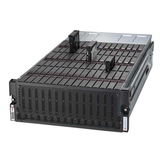
Page 13: Chassis Top
Chapter 1: Introduction Chassis Top 90 Drives Mounted Vertically Figure 1-4. Top View... -
Page 14: Motherboard Layout
SuperStorage Server 6048-E1CR90L User's Manual 1.5 Motherboard Layout Below is a layout of the X10DSC-TP4S with jumper, connector and LED locations. See the following table for descriptions. For detailed descriptions, pinout information and jumper settings, refer to Chapter 4. SFPX4/ SFPX3/ SFPX2/ SFPX1/... -
Page 15: Led Description
4-pin (+5V/+12V) power connector for HDD use JSAS SAS 3008 add-on module connector used for SAS expanders (Part No: AOC-SAS3- 946E90) JSIOM Supermicro I/O module connector (SIOM) for SIOM card use JSPK1 Internal speaker/buzzer JTPM1 TPM (Trusted Platform Module)/Port 80 header... -
Page 16: System Block Diagram
SuperStorage Server 6048-E1CR90L User's Manual System Block Diagram Processor 1 Processor 2 DDR4 DDR4 Figure 1-6. Intel PCH C612 Chipset: System Block Diagram Note: This is a general block diagram and may not exactly represent the features on your motherboard. See the System Specifications appendix for the actual specifications of your motherboard. -
Page 17: Chapter 2 Installation In A Rack
Chapter 2 Installation in a Rack Chapter 2 Installation in a Rack This chapter provides advice and instructions for mounting your system in a rack. 2.1 Preparing for Setup The box in which the system was shipped should include the hardware needed to install it into the rack. -
Page 18: Server Precautions
SuperStorage Server 6048R-E1CR90L User's Manual Server Precautions • Review the electrical and general safety precautions in Chapter 3. • Determine the placement of each component in the rack before you install the rails. • Install the heaviest server components at the bottom of the rack first and then work your way up. -
Page 19: Reliable Ground
Chapter 2 Installation in a Rack Reliable Ground A reliable ground must be maintained at all times. To ensure this, the rack itself should be grounded. Particular attention should be given to power supply connections other than the direct connections to the branch circuit (i.e. the use of power strips, etc.). To prevent bodily injury when mounting or servicing this unit in a rack, you must take special precautions to ensure that the system remains stable. -
Page 20: Installing The Rails
SuperStorage Server 6048R-E1CR90L User's Manual 2.2 Installing the Rails There are a variety of rack units on the market, which may require a slightly different assembly procedure. Do not use a two post "telco" type rack. This rail set fits a rack between 28" and 34"... -
Page 21: Releasing The Inner Rail
Chapter 2 Installation in a Rack Releasing the Inner Rail To mount the rails onto the chassis, first release the inner rail from the outer rails. Each inner rail has a locking latch that prevents the server from coming completely out of the rack when when the chassis is pulled out for servicing. -
Page 22: Installing The Inner Rails
SuperStorage Server 6048R-E1CR90L User's Manual Installing the Inner Rails Install the inner rails onto the chassis. 1. Identify the left and right inner rails. 2. Place the inner rail firmly against the side of the chassis, aligning the mushroom pins on the side of the chassis with the holes in the inner rail. -
Page 23: Installing The Outer Rails Onto The Rack
Chapter 2 Installation in a Rack Installing the Outer Rails onto the Rack The outer rail is actually two parts that slide to lengthen the rail. Each end of the assembled outer rail includes a bracket with round pegs to fit into your rack holes. The left and right rail and the front and rear of each rail is labeled. -
Page 24: Installing The Chassis Into A Rack
SuperStorage Server 6048R-E1CR90L User's Manual 2.3 Installing the Chassis into a Rack Once rails are attached to the chassis and the rack, you can install the server. Caution! The chassis is heavy. Mount or remove the chassis using sufficient personel and/or a lift. -
Page 25: Removing The Chassis From The Rack
Chapter 2 Installation in a Rack Figure 2-6. Installing the Server into the Rack Note: Figures are for illustrative purposes. Always install servers from the bottom up. Removing the Chassis from the Rack To remove the chassis from the rack, use the previous procedure, "Releasing the Inner Rail." Caution! The loaded chassis is heavy. -
Page 26: Removing The Outer Rails From The Rack
SuperStorage Server 6048R-E1CR90L User's Manual Removing the Outer Rails from the Rack If you want to move or remove the outer rails from the rack, first remove the server completely. 1. Push the middle rail fully into the outer rail. There is a small locking tab on the inside of the middle rail. -
Page 27: Assembling The Cable Management Arm
Chapter 2 Installation in a Rack 2.4 Assembling the Cable Management Arm The SC946E1C chassis supports a cable management arm (CMA) which helps to keep the cables organized and clear of the rack and rail mechanisms. The swing arm functionality of the cable management arm keeps the cables clear while maintenance is being performed on the system. - Page 28 SuperStorage Server 6048R-E1CR90L User's Manual Assembling the Cable Managment Arm 1. Identify the components of the cable management arm as shown below: Figure 2-9. Identifying the Cable Managment Arm Components Cable Arm Managment Components CMA connector #1 CMA connector #1 base on the inner member...
- Page 29 Chapter 2 Installation in a Rack 3. Install CMA connector #2 (C) onto CMA connector #2 base (D) on the inner member. CMA Connector #2 CMA Connector #2 Apart Assembled Figure 2-11. Installing the CMA Connector #1 onto the Inner Member 4.
-
Page 30: Swing Arm Functionality Of The Cable Arm
SuperStorage Server 6048R-E1CR90L User's Manual Swing Arm Functionality of the Cable Arm Swing Arm Function (Swings Right) 1. Press the button on CMA connector #1 (A). 2. Pull back on CMA connector #1 to release it from the base. 3. Rotate the arm ninety degrees to the right. -
Page 31: Chapter 3 Maintenance And Component Installation
Chapter 3: Maintenance and Component Installation Chapter 3 Maintenance and Component Installation This chapter provides instructions on installing and replacing main system components. To assure compatibility, only use components that match the specifications or part numbers given. Installation or replacement of most components require that power first be removed from the system. -
Page 32: Accessing The System
SuperStorage Server 6048-E1CR90L User's Manual 3.2 Accessing the System The SC946E1C chassis top cover opens to access the storage drives, as described in the section, "Storage Drives." Other server components can be accessed from the chassis rear, described in the section, "Power Distributor Board." Caution: Except for short periods of time, do not operate the server without the cover in place. - Page 33 Chapter 3: Maintenance and Component Installation Figure 3-2. Access to the Motherboard and Other Components...
-
Page 34: Motherboard Components
CPU socket cap is in place and none of the socket pins are bent; otherwise, contact your retailer immediately. • Refer to the Supermicro website for updates on CPU support. Installing the Processor(s) If the system is powered on, remove power as described in Section 3.1. - Page 35 Chapter 3: Maintenance and Component Installation 3. With the second lever fully retracted, gently push down on the "Open 1st" lever to loosen the load plate. Lift the load plate with your fingers to open it completely. 4. Pop the plastic cap marked "Warning" out of the load plate. Open the load IMPORTANT! plate.
- Page 36 SuperStorage Server 6048-E1CR90L User's Manual 8. Make sure the locking mechanism on the "Close 1st" lever catches the lip of the load plate. Close and lock the "Close 1st" lever. 9. Close and lock the "Open 1st" lever. Push down and lock the lever labeled "Close 1st".
- Page 37 Chapter 3: Maintenance and Component Installation Removing a Heatsink We do not recommend removing the heatsink. If necessary, please follow the instructions below to prevent damage to the CPU or the CPU socket. 1. Unscrew and remove the heatsink screws. 2.
-
Page 38: Memory Installation
2400/2133/1866/1600/1333MHz. Populating these DIMM modules with a pair of memory modules of the same type and size will result in interleaved memory, which will improve memory performance. Check the Supermicro website for possible updates to memory support. DIMM Module Population Configuration For optimal memory performance, follow the table below when populating memory. - Page 39 Chapter 3: Maintenance and Component Installation Populating Memory Modules Speed (MT/s); Voltage (V); Slots per Channel (SPC) and DIMMs per Channel (DPC) Ranks DIMM Capacity 1 Slot per Channel Per DIMM (GB) Type and Data 1 DPC Width E5-2600 V3 E5-2600 V4 4 Gb 8 Gb...
-
Page 40: Install Procedure
To remove a DIMM module, unlock the release tabs then pull the module from the slot. Caution: Exercise caution when installing or removing memory modules to prevent damage to the DIMMs or slots. Note: Visit the product page on the Supermicro website for possible updates to memory support (www.supermicro.com). -
Page 41: Motherboard Battery
Chapter 3: Maintenance and Component Installation Motherboard Battery The motherboard uses non-volatile memory to retain system information when system power is removed. This memory is powered by two lithium batteries residing on the motherboard, one battery for each node. Replacing the Battery 1. -
Page 42: Chassis Components
Caution: When shipping the system, remove the drives from the chassis for travel, whether the chassis is shipped alone or in a rack. The original Supermicro packaging includes boxes for the drives in carriers. Drive Carrier Indicators Each hard drive carrier has two LED indicators: an activity indicator and a status indicator. In RAID configurations, the status indicator lights to indicate the status of the drive. -
Page 43: Controller To Drive Configuration
Figure 3-5. This design helps balance performance. This zoning configuration is accomplished by factory installed firmware on the expanders. Note: If you want to change the zoning configuration, contact Supermicro Technical Support for assistance. -
Page 44: Adding Or Replacing Hard Drives
SuperStorage Server 6048-E1CR90L User's Manual Adding or Replacing Hard Drives Opening the Storage Compartment Cover 1. Release the two thumb screws on the right side of the chassis. 2. Lift the cover. The cover holds an open position at 100 degrees without additional support. - Page 45 Chapter 3: Maintenance and Component Installation Removing a Hard Drive Carrier from the Storage Compartment 1. Open the storage compartment cover. 2. Slide the release button on the drive carrier, which opens the carrier handle. 3. Use the handle to pull the drive carrier up and out. Caution: Except for short periods of time, such as while swapping hard drives, do not operate the server with the drive carriers removed from the bays.
- Page 46 SuperStorage Server 6048-E1CR90L User's Manual Installing a 3.5" Hard Disk Drive With the drive carrier removed from the storage compartment: 1. Under the main the carrier handle, find and the lift the breakout lever and pull out the side of the carrier. Carrier Breakout Lever...
-
Page 47: Two Hard Disk Drives At The Chassis Rear
Chapter 3: Maintenance and Component Installation Two Hard Disk Drives at the Chassis Rear Rear HDD Bays Figure 3-8. HDDs at Chassis Rear There is room for two optional hot-swap 2.5" drives in the rear of the chassis. Installing 2.5" Hard Disk Drives at the Chassis Rear 1. -
Page 48: System Cooling
SuperStorage Server 6048-E1CR90L User's Manual System Cooling Five hot-swappable, heavy-duty rear mounted fans provide cooling. They can be replaced without powering down the system. Fan speed is controlled by a system temperature setting in IPMI. If a fan fails, the remaining fans will ramp up to full speed. -
Page 49: Checking The Server Air Flow
Overheat Temperature Setting Some backplanes allow the overheat temperature to be set at 45, 50, or 55 by changing a jumper setting. For more information, consult the backplane user manual at www.supermicro. com. (Click Support, then the Manuals link.) Responses If the server overheats: 1. -
Page 50: Power Supply
It should be replaced as soon as convenient. The power supply modules are hot-swappable, meaning they can be changed without powering down the system. New units can be ordered directly from Supermicro or authorized distributors. These power supplies are auto-switching capable. This feature enables them to automatically sense the input voltage and operate at a 100-120v or 180-240v. -
Page 51: Power Distributor Board
Chapter 3: Maintenance and Component Installation Power Distributor Board The chassis comes equipped with a PDB-PT946-S386 power distributor. In the unlikely event that you need to replace the power distributor, use the following instructions. Removing the Power Distributor 1. Power down the chassis as described in section 3.1. 2. - Page 52 SuperStorage Server 6048-E1CR90L User's Manual Figure 3-13. Removing the Power Distributor Board 8. Remove the eight screws securing the power distributor board to the power distributor bracket and set them aside for later use. 9. Pull the power distributor board off the bracket. 10.
-
Page 53: Motherboard Removal
Chapter 3: Maintenance and Component Installation Motherboard Removal The motherboard is mounted on a tray that slides out the rear of the chassis. 1. Power down the system as described in Section 3.1. 2. Remove the power supply modules, the power supply cage and the power distributor board as described in previous sections. - Page 54 SuperStorage Server 6048-E1CR90L User's Manual Notes...
-
Page 55: Chapter 4 Motherboard Connections
Pins 4 Power Distribution Board A power distribution board header is located at JPSB on the motherboard. Install a Supermicro power distribution board (part number: PDB-PT946-S386) on this header to maximize power efficiency and enhance power management. See the layout below for the location. -
Page 56: Headers And Connectors
+3.3V LAD1 LAD0 No Connection No Connection +3V STBY SERIRQ CLKRUN# LPCPD# No Connection SIOM Connector Header (Optional) A connection slot is available for an optional Supermicro I/O Module (SIOM). This card provides a variety of options for network connections. -
Page 57: Control Panel
SAS AOM Connector Header A 3008 Add-On Module (AOM) connector is located at JSAS on the motherboard. Install a Supermicro SAS Expander add-on card (Part Number: AOC-SAS3-946E90) on this header to use SAS expanders. When the AOC-SAS3-946E90 add-on card is installed, onboard 3OO8 SAS controllers will be enabled. - Page 58 SuperStorage Server 6048-E1CR90L User's Manual Reset Button The Reset Button connection is located on pins 3 and 4 of JF1. Attach it to a hardware reset switch on the computer case. Reset Button Pin Definitions (JF1) Pin# Definition Reset Ground Power Fail LED The Power Fail LED connection is located on pins 5 and 6 of JF1.
- Page 59 Chapter 4: Motherboard Connections HDD LED/UID Switch The HDD LED/UID Switch connection is located on pins 13 and 14 of JF1. Attach a cable to Pin 14 to show hard drive activity status. Attach a cable to Pin 13 to use UID switch. Refer to the table below for pin definitions.
-
Page 60: Data Cables
SuperStorage Server 6048-E1CR90L User's Manual Data Cables The data cables in the system have been carefully routed to maintain airflow efficiency. If you disconnect any of these cables, take care to re-route them as they were originally when reconnecting them. Important! Make sure the the cables do not come into contact with the fans. -
Page 61: Ports
Chapter 4: Motherboard Connections 4.3 Ports Figure 4-2. Rear I/O Ports Rear I/O Ports Description Description UID (SW1) USB 2 (USB 2.0) COM1 USB 3 (USB 2.0) SFP+/LAN1 USB 4 (USB 2.0) or SFP+/LAN2 USB 8 (USB 3.0) USB 5 (USB 2.0) or SFP+/LAN3 USB 9 (USB 3.0) IPMI_LAN... - Page 62 SuperStorage Server 6048-E1CR90L User's Manual SFP/LAN Port 1 - SFP/LAN Port 4 Four SFP (Small Form-factor Pluggable) networking devices/LAN ports are located on the I/O backpanel. Supported by the Intel 710 controller, they provide 10 gigabit LAN support for complex telecommunication and data communications applications. Appropriate cables are required for these connections.
-
Page 63: Jumpers
Chapter 4: Motherboard Connections 4.4 Jumpers Explanation of Jumpers To modify the operation of the motherboard, jumpers are used to choose between optional settings. Jumpers create shorts between two pins to change the function associated with it. Pin 1 is identified with a square solder pad on the printed circuit board. See the motherboard layout page for jumper locations. - Page 64 SuperStorage Server 6048-E1CR90L User's Manual VGA Enable/Disable Close pins 2 and 3 of jumper JPG1 to disable the onboard VGA port using the onboard graphics controller. The default setting is Enabled. VGA Enable/Disable Jumper Settings Jumper Setting Definition Pins 1-2 Enabled Pins 2-3 Disabled...
-
Page 65: Led Indicators
Chapter 4: Motherboard Connections Manufacturer Mode Select Close the Manufacturer Mode (ME) Select Jumper JPME2 to bypass SPI flash security and force the system to use the Manufacturer mode. ME mode allows the user to flash the system firmware from a host server to modify system settings of a machine at a remote location. Manufacturer Mode Jumper Settings Jumper Setting... - Page 66 SuperStorage Server 6048-E1CR90L User's Manual BMC Heartbeat LED A BMC (Baseboard Management Controller) Heartbeat LED is located at LEDM1 on the motherboard. When LEDM1 is blinking, BMC functions normally. BMC Hearbeat LED Color/State Definition Green: Blinking BMC: Normal SAS Heartbeat LEDs Two SAS Heartbeat LEDs are located on the motherboard.
-
Page 67: Sata Connections
Parallel ATA. Note 1 Supermicro SuperDOMs are yellow SATADOM connectors with power pins built in and do not require separate external power cables. These connectors are backward-compatible with non-Supermicro SATADOMs that require an external power supply. -
Page 68: Chapter 5 Software
You must first configure RAID settings (if using RAID) before you install the Windows OS and the software drivers. To configure RAID settings, please refer to the RAID Configuration User Guides posted on our website at www.supermicro.com/support/manuals. Installing the Windows OS for a RAID System 1. -
Page 69: Driver Installation
Chapter 5: Software 5.2 Driver Installation The Supermicro FTP site contains drivers and utilities for your system at ftp://ftp.supermicro. com. Some of these must be installed, such as the chipset driver. After accessing the FTP site, go into the CDR_Images directory and locate the ISO file for your motherboard. -
Page 70: Superdoctor ® 5
5.3 SuperDoctor ® The Supermicro SuperDoctor 5 is a program that functions in a command-line or web-based interface for Windows and Linux operating systems. The program monitors such system health information as CPU temperature, system voltages, system power consumption, fan speed, and provides alerts via email or Simple Network Management Protocol (SNMP). -
Page 71: Chapter 6 Bios
Chapter 6: BIOS Chapter 6 BIOS 6.1 Introduction This chapter describes the AMI BIOS setup utility for the X10DSC-TP4S and provides the instructions on navigating the setup screens. The BIOS is stored in a Flash EEPROM and can be updated. Note: Due to periodic changes to the BIOS, some settings may have been added or deleted since this manual was published. - Page 72 HH:MM:SS format. Note: The time is in the 24-hour format. For example, 5:30 P.M. appears as 17:30:00. The date's default value is 01/01/2016 after RTC reset. Supermicro X10DSC-TP4S (Motherboard model) BIOS Version Build Date (of the BIOS) CPLD (Complex Programmable Logic Device) Version: This item displays the CPLD version used in the system.
-
Page 73: Advanced Setup Configurations
Chapter 6: BIOS 6.3 Advanced Setup Configurations Use the arrow keys to select the Advanced tab and press <Enter> to access the submenu items. Caution: Take caution when changing the Advanced settings. An incorrect value, a very high DRAM frequency, or an incorrect DRAM timing setting may make the system unstable. If this occurs, revert to the manufacture default settings. -
Page 74: Power Configuration
SuperStorage Server 6048-E1CR90L User's Manual AddOn ROM Display Mode Use this item to set the display mode for the Option ROM. Select Keep Current to use the current AddOn ROM display setting. Select Force BIOS to use the Option ROM display mode set by the system BIOS. -
Page 75: Cpu Configuration
Chapter 6: BIOS CPU Configuration This submenu displays the following CPU information as detected by the BIOS. It also allows the user to configure CPU settings. • Processor Socket • Processor ID • Processor Frequency • Processor Max Ratio •... - Page 76 SuperStorage Server 6048-E1CR90L User's Manual Hardware Prefetcher (Available when supported by the CPU) If set to Enable, the hardware prefetcher will prefetch streams of data and instructions from the main memory to the L2 cache to improve CPU performance. The options are Disable and Enable.
-
Page 77: Advanced Power Management Configuration
Chapter 6: BIOS Advanced Power Management Configuration Advanced Power Management Configuration Power Technology Select Energy Efficient to support power-saving mode. Select Custom to customize system power settings. Select Disable to disable power-saving settings. The options are Disable, Energy Efficient, and Custom. Energy Performance Tuning Select Enable for energy-performance tuning support to enhance energy efficiency, which might compromise system performance. -
Page 78: Chipset Configuration
SuperStorage Server 6048-E1CR90L User's Manual the P-state coordination type for hardware components only. Select SW_ALL to change the P-state coordination type for all software installed in the system. Select SW_ANY to change the P-state coordination type for a software program in the system. The options are HW_All, SW_ALL, and SW_ANY. -
Page 79: Iio Configuration
Chapter 6: BIOS IIO Configuration EV DFX (Device Function On-Hide) Features When this feature is set to Enable, the EV_DFX Lock Bits that are located on a processor will always remain clear during electric tuning. The options are Disable and Enable. Snoop Response Hold Off Use this option to set the snoop response hold-off value. - Page 80 SuperStorage Server 6048-E1CR90L User's Manual PCI-E Port Link (Available for the II01 Configuration only) Use this item to disable the physical link connected to a PCI-E port specified by a user so that no training will take place on the component-level while the PCI-E configuration commands are still in full force.
- Page 81 Chapter 6: BIOS Socket 1 PceiD01F0 - Port 1A/Socket 1 PceiD02F0 - Port 2A/ Socket 1 PceiD03F0 - Port 3A/Socket 1 PceiD03F2 - Port 3C (for IIO1 Configuration) PCI-E Port (Available for the II01 Configuration only) Select Enable to enable a PCI-E port specified by the user. Select Disable to de-activate a PCI-E port specified by the user.
- Page 82 SuperStorage Server 6048-E1CR90L User's Manual Non-Fatal Err (Error) Over Select Enable to force a non-fatal error that has occurred to the port specified by the user to be prorogated to the II0 core error logic. The options are Disable and Enable. Corr Err (Correctable Error) Over Select Enable to force a correctable error that has occurred to the port specified by the user to be prorogated to the II0 core error logic.
-
Page 83: Ioat Configuration
Chapter 6: BIOS Hide Port? Use this item to hide the root port from the operating system. The options are No and yes. IOU0 Non-Posted Prefetch/IOU1 Non-Posted Prefetch/IOU2 Non-Posted Prefetch Select Enable to enble Non-Posted Prefetch support for a PCI-E slot specified by the user. The options are Disable and Enable. - Page 84 SuperStorage Server 6048-E1CR90L User's Manual QPI (Quick Path Interconnect) Configuration QPI General Configuration QPI Status The following information will display: • Number of CPU • Number of II0 • Current QPI Link Speed • Current QPI Link Frequency • QPI Global MMIO Low Base/Limit •...
-
Page 85: Memory Configuration
Chapter 6: BIOS Isoc Mode Select Enable for Isochronous support to meet QoS (Quality of Service) requirements. This feature is especially important for Intel's Virtualization Technology. The options are Enable and Disable. Memory Configuration This submenu allows the user to configure Integrated Memory Controller (IMC) settings. Enforce POR Select Enabled to enforce POR restrictions on DDR4 frequency and voltage programming. -
Page 86: Dimm Information
SuperStorage Server 6048-E1CR90L User's Manual DRAM RAPL (Running Average Power Limit) Baseline Use this feature to set the run-time power-limit baseline for DRAM modules. The options are Disable, DRAM RAPL Mode 0, and DRAM RAPL Mode 1. Set Throttling Mode Throttling improves CPU reliability and reduces power consumption via automatic-voltage control during CPU idle states. -
Page 87: South Bridge Configuration
Chapter 6: BIOS Patrol Scrub Interval This feature allows you to decide how many hours the system should wait before the next complete patrol scrub is performed. Use the keyboard to enter a value from 0-24. The Default setting is 24. Demand Scrub Demand Scrubbing is a process that allows the CPU to correct correctable memory errors found on a memory module. -
Page 88: Sata Configuration
SuperStorage Server 6048-E1CR90L User's Manual USB 3.0 Support Select Enabled for USB 3.0 support. The options are Smart Auto, Auto, Enabled, and Disabled. SATA Configuration When this submenu is selected, AMI BIOS automatically detects the presence of the SATA devices that are supported by the Intel PCH chip and displays the following items: SATA Controller This item enables or disables the onboard SATA controller supported by the Intel PCH chip. - Page 89 Chapter 6: BIOS Serial ATA Port 0~ Port 5 This item indicates if a SATA port specified by the user is installed (present) or not. Port 0 ~ Port 5 SATA Device Type (Available when a SATA port is detected) Use this item to specify if the SATA port specified by the user should be connected to a Solid State drive or a Hard Disk Drive.
- Page 90 SuperStorage Server 6048-E1CR90L User's Manual sSATA Port 0 ~ Port 3 Hot Plug Select Enabled to enable hot-plugging support for a port specified by the user, which will allow the user to replace a sSATA disk drive installed on this port without shutting down the system.
- Page 91 Chapter 6: BIOS Configure as eSATA (Available for the sSATA Port 0 Only) Select Enabled to configure sSATA Port 0 as an external sSATA port. The options are Enabled and Disabled. sSATA Port 0 ~ Port 3 Spin Up Device On an edge detect from 0 to 1, set this item to allow the PCH to start a COMRESET initialization to the device.
- Page 92 SuperStorage Server 6048-E1CR90L User's Manual SERR# Generation Select Enabled for the BIOS to generate a SERR (System Error) number The options are Enabled and Disabled. PCI PERR/SERR Support Select Enabled to support PERR (PCI/PCI-E Parity Error)/SERR (System Error) runtime error reporting for a PCI/PCI-E slot.
-
Page 93: Super Io Configuration
Chapter 6: BIOS Onboard Video Option ROM Use this item to select the Option ROM type for the onboard video device for system boot. The options are Disabled, Legacy, and EFI. VGA Priority Use this item to select the graphics device to be used as the primary video display for system boot. -
Page 94: Serial Port Console Redirection
SuperStorage Server 6048-E1CR90L User's Manual Device Settings This item displays the base I/O port address and the Interrupt Request address for a serial port specified by the user. The default setting for Serial Port 1 is IO=3F8h IRQ=4, and for Serial Port 2 is IO=2F8h IRQ=3. - Page 95 Chapter 6: BIOS Bits Per second Use this item to set the transmission speed for a serial port used in Console Redirection. Make sure that the same speed is used in the host computer and the client computer. A lower transmission speed may be required for long and busy lines. The options are 9600, 19200, 38400, 57600 and 115200 (bits per second).
- Page 96 SuperStorage Server 6048-E1CR90L User's Manual Putty KeyPad Use this item to select Function Keys and KeyPad settings for Putty, which is a terminal emulator designed for the Windows OS. The options are VT100, LINUX, XTERMR6, SCO, ESCN, and VT400. Redirection After BIOS Post Use this item to enable or disable legacy Console Redirection after BIOS POST (Power-On Self-Test).
- Page 97 Chapter 6: BIOS do not want to send a parity bit with your data bits in transmission. Select Mark to add a mark as a parity bit to be sent along with the data bits. Select Space to add a Space as a parity bit to be sent with your data bits.
- Page 98 SuperStorage Server 6048-E1CR90L User's Manual (EMS) Console Redirection Select Enabled to use a COM port selected by the user for EMS Console Redirection. The options are Enabled and Disabled. *If the item above set to Enabled, the following items will become available for user's configuration: EMS Console Redirection Settings (Available when EMS Console Redirection is enabled)
-
Page 99: Acpi Settings
Note: If the option for this item (TXT Support) is set to Enabled, be sure to disable EV DFX (Device Function On-Hide) support for the system to work properly. (EV DFX is under "IIO Configuration" in the "Chipset/North Bridge" submenu. For more information on TPM, please refer to the TPM manual at http://www.supermicro.com/manuals/other/AOM-TPM- 9655V_9655H.pdf ACPI Settings ... -
Page 100: Event Logs
SuperStorage Server 6048-E1CR90L User's Manual High Precision Event Timer Select Enabled to activate the High Precision Event Timer (HPET) that produces periodic interrupts at a much higher frequency than a Real-time Clock (RTC) does in synchronizing multimedia streams, providing smooth playback and reducing the dependency on other timestamp calculation devices, such as an x86 RDTSC Instruction embedded in the CPU. - Page 101 Chapter 6: BIOS Enabling/Disabling Options SMBIOS Event Log Select Enabled to enable SMBIOS (System Management BIOS) Event Logging during system boot. The options are Enabled and Disabled. Runtime Error Logging Support Select Enable to support Runtime Error logging. The options are Enabled and Disabled. If this item is set to Enabled, the following item will be available for configuration: Erasing Settings Erase Event Log...
-
Page 102: Ipmi
SuperStorage Server 6048-E1CR90L User's Manual 6.5 IPMI Use this tab page to configure Intelligent Platform Management Interface (IPMI) settings. The following items will be displayed: • IPMI Firmware Revision • Status of BMC System Event Log Enabling/Disabling Options SEL Components Select Enabled to enable all system event logging support at bootup. -
Page 103: Bmc Network Configuration
Chapter 6: BIOS keep all system event logs after each system reboot. The options are No, Yes, On next reset, and Yes, On every reset. When SEL is Full This feature allows the user to determine what the AMI BIOS should do when the system event log is full. -
Page 104: Security
SuperStorage Server 6048-E1CR90L User's Manual This item displays the sub-network that this computer belongs to. The value of each three- digit number is separated by dots and it should not exceed 255. Station MAC Address This item displays the Station MAC address for this computer. Mac addresses are 6 two-digit hexadecimal numbers. -
Page 105: Secure Boot Menu
Chapter 6: BIOS Administrator Password Use this feature to set the administrator password which is required before entering the BIOS setup utility. The length of the password should be from 3 characters to 20 characters long. User Password (Available after an Administrator Password is entered) Use this feature to set the user password which is required to enter the BIOS setup utility. - Page 106 SuperStorage Server 6048-E1CR90L User's Manual Key Exchange Key This feature allows the user to configure and save Key-Exchange-Key settings. Authorized Signatures This feature allows the user to set and save authorized signatures and grant access to those whose names appear on the list. Forbidden Signatures ...
-
Page 107: Boot
Chapter 6: BIOS 6.7 Boot Use this tab page to configure Boot Settings. Boot Configuration Boot Mode Select Use this item to select the type of device to be used for system boot. The options are Legacy, UEFI, and Dual. Fixed Boot Order Priorities This option prioritizes the order of bootable devices from which the system will boot. - Page 108 SuperStorage Server 6048-E1CR90L User's Manual When the item above -"Boot Mode Select" is set to UEFI, the following items will be display for configuration: • Boot Option #1 - Boot Option #8 Add New Boot Option Use this item to select a new boot device to add to the boot priority list. Add New Boot Option Use this feature to select the target boot device to add to the boot priority list.
-
Page 109: Save & Exit
Chapter 6: BIOS 6.8 Save & Exit Use this tab page to configure Save & Exit settings. Save Options Save Changes and Exit Select this item to save the changes you've made and to exit from the BIOS setup. For the changes to take effect, please reboot your computer. - Page 110 SuperStorage Server 6048-E1CR90L User's Manual Discard Changes Select this item to discard all the changes and return to the AMI BIOS setup utility. Select Yes and press <Enter> to discard all changes made. Default Options Restore Optimized Defaults Select this item and press <Enter> to load the manufacture default settings which are designed for maximum system performance but not for maximum stability.
-
Page 111: Appendix A Bios Error Codes
Appendix A: BIOS Error Codes Appendix A BIOS Error Codes A-1 BIOS Error Beep (POST) Codes During the POST (Power-On Self-Test) routines, which are performed each time the system is powered on, errors may occur. Non-fatal errors are those which, in most cases, allow the system to continue the boot-up process. - Page 112 When BIOS performs the Power On Self Test, it writes checkpoint codes to I/O port 0080h. If the computer cannot complete the boot process, a diagnostic card can be attached to the computer to read I/O port 0080h (Supermicro p/n AOC-LPC80-20). For information on AMI updates, please refer to http://www.ami.com/products/.
-
Page 113: Appendix B Standardized Warning Statements For Ac Systems
Supermicro's Technical Support department for assistance. Only certified technicians should attempt to install or configure components. Read this appendix in its entirety before installing or configuring components in the Supermicro chassis. These warnings may also be found on our website at http://www.supermicro.com/about/... - Page 114 Appendix B: Standardized Warning Statements Warnung WICHTIGE SICHERHEITSHINWEISE Dieses Warnsymbol bedeutet Gefahr. Sie befinden sich in einer Situation, die zu Verletzungen führen kann. Machen Sie sich vor der Arbeit mit Geräten mit den Gefahren elektrischer Schaltungen und den üblichen Verfahren zur Vorbeugung vor Unfällen vertraut. Suchen Sie mit der am Ende jeder Warnung angegebenen Anweisungsnummer nach der jeweiligen Übersetzung in den übersetzten Sicherheitshinweisen, die zusammen mit diesem Gerät ausgeliefert wurden.
-
Page 115: Installation Instructions
SuperServer 5038MD-H24TRF User's Manual جسذٌة اصابة ًتتسبب ف حالة ٌوكي أى ًاًك ف خطز ًٌٌع هذا الزهز !تحذٌز الذوائز بالوخاطز الٌاجوة عي ي على علن ، ك هعذات تعول على أي قبل أى الكهزبائٍة حىادث أي وقىع وٌع ل الىقائٍة سات... -
Page 116: Circuit Breaker
Appendix B: Standardized Warning Statements Warnung Vor dem Anschließen des Systems an die Stromquelle die Installationsanweisungen lesen. ¡Advertencia! Lea las instrucciones de instalación antes de conectar el sistema a la red de alimentación. Attention Avant de brancher le système sur la source d'alimentation, consulter les directives d'installation. מתח... - Page 117 SuperServer 5038MD-H24TRF User's Manual Warnung Dieses Produkt ist darauf angewiesen, dass im Gebäude ein Kurzschluss- bzw. Überstromschutz installiert ist. Stellen Sie sicher, dass der Nennwert der Schutzvorrichtung nicht mehr als: 250 V, 20 A beträgt. ¡Advertencia! Este equipo utiliza el sistema de protección contra cortocircuitos (o sobrecorrientes) del edificio.
-
Page 118: Power Disconnection Warning
Appendix B: Standardized Warning Statements Power Disconnection Warning Warning! The system must be disconnected from all sources of power and the power cord removed from the power supply module(s) before accessing the chassis interior to install or remove system components. 電源切断の警告... -
Page 119: Equipment Installation
SuperServer 5038MD-H24TRF User's Manual امداد وحدة من سهك انكهرباء وإزانت انطاقت مصادر من جميع اننظاو يجب فصم قبم انطاقت الجهاز مكىناث نتثبيج أو إزانت ههيكم ن انمناطق انداخهيت انىصىل إنى 경고! 시스템에 부품들을 장착하거나 제거하기 위해서는 섀시 내부에 접근하기 전에 반드시 전원 공급장치로부터... -
Page 120: Restricted Area
Appendix B: Standardized Warning Statements Attention Il est vivement recommandé de confier l'installation, le remplacement et la maintenance de ces équipements à des personnels qualifiés et expérimentés. !אזהרה .הציוד או לתת שירות עבור הציוד אי להתקין, להחליף את צוות מוסמך בלבד רש هذا... - Page 121 SuperServer 5038MD-H24TRF User's Manual Warnung Diese Einheit ist zur Installation in Bereichen mit beschränktem Zutritt vorgesehen. Der Zutritt zu derartigen Bereichen ist nur mit einem Spezialwerkzeug, Schloss und Schlüssel oder einer sonstigen Sicherheitsvorkehrung möglich. ¡Advertencia! Esta unidad ha sido diseñada para instalación en áreas de acceso restringido. Sólo puede obtenerse acceso a una de estas áreas mediante la utilización de una herramienta especial, cerradura con llave u otro medio de seguridad.
-
Page 122: Battery Handling
Appendix B: Standardized Warning Statements Battery Handling Warning! There is the danger of explosion if the battery is replaced incorrectly. Replace the battery only with the same or equivalent type recommended by the manufacturer. Dispose of used batteries according to the manufacturer's instructions 電池の取り扱い... -
Page 123: Redundant Power Supplies
SuperServer 5038MD-H24TRF User's Manual فعليل بطريقة غير صحيحة البطارية انفجار في حالة اسحبذال من هناك خطر اسحبذال البطارية به الشرمة المصنعة أوصث مما أو ما يعادلها بنفس النىع فقط حعليمات الشرمة الصانعة المسحعملة وفقا ل جخلص من البطاريات 경고! 배터리가 올바르게 교체되지 않으면 폭발의 위험이 있습니다. 기존 배터리와 동일하거나 제 조사에서... - Page 124 Appendix B: Standardized Warning Statements ¡Advertencia! Puede que esta unidad tenga más de una conexión para fuentes de alimentación. Para cortar por completo el suministro de energía, deben desconectarse todas las conexiones. Attention Cette unité peut avoir plus d'une connexion d'alimentation. Pour supprimer toute tension et tout courant électrique de l'unité, toutes les connexions d'alimentation doivent être débranchées.
-
Page 125: Backplane Voltage
SuperServer 5038MD-H24TRF User's Manual Backplane Voltage Warning! Hazardous voltage or energy is present on the backplane when the system is operating. Use caution when servicing. バックプレーンの電圧 システムの稼働中は危険な電圧または電力が、 バックプレーン上にかかっています。 修理する際には注意く ださい。 警告 当系统正在进行时,背板上有很危险的电压或能量,进行维修时务必小心。 警告 當系統正在進行時,背板上有危險的電壓或能量,進行維修時務必小心。 Warnung Wenn das System in Betrieb ist, treten auf der Rückwandplatine gefährliche Spannungen oder Energien auf. -
Page 126: Comply With Local And National Electrical Codes
Appendix B: Standardized Warning Statements اللىحة أوالطاقة المىجىدة على التيار الكهزبائي مه خطز هناك هذا الجهاس خدمة كه حذرا عند يعمل النظام عندما يكىن 경고! 시스템이 동작 중일 때 후면판 (Backplane)에는 위험한 전압이나 에너지가 발생 합니다. 서비스 작업 시 주의하십시오. Waarschuwing Een gevaarlijke spanning of energie is aanwezig op de backplane wanneer het systeem in gebruik is. -
Page 127: Product Disposal
SuperServer 5038MD-H24TRF User's Manual תיאום חוקי החשמל הארצי !אזהרה הציוד חייבת להיות תואמת לחוקי החשמל המקומיים והארציים התקנת المتعلقة المحلية والىطىية قىاويه يجب أن يمتثل لل الكهربائية تركيب المعدات بالكهرباء 경고! 현 지역 및 국가의 전기 규정에 따라 장비를 설치해야 합니다. Waarschuwing Bij installatie van de apparatuur moet worden voldaan aan de lokale en nationale elektriciteitsvoorschriften. -
Page 128: Hot Swap Fan Warning
Appendix B: Standardized Warning Statements Attention La mise au rebut ou le recyclage de ce produit sont généralement soumis à des lois et/ou directives de respect de l'environnement. Renseignez-vous auprès de l'organisme compétent. סילוק המוצר !אזהרה .חוקי המדינה סילוק סופי של מוצר זה חייב להיות בהתאם להנחיות ו القىانين... - Page 129 SuperServer 5038MD-H24TRF User's Manual Warnung Gefährlich Bewegende Teile. Von den bewegenden Lüfterblätter fern halten. Die Lüfter drehen sich u. U. noch, wenn die Lüfterbaugruppe aus dem Chassis genommen wird. Halten Sie Finger, Schraubendreher und andere Gegenstände von den Öffnungen des Lüftergehäuses entfernt.
-
Page 130: Power Cable And Ac Adapter
Brand entstehen. Elektrische Geräte und Material Safety Law verbietet die Verwendung von UL-oder CSA-zertifizierte Kabel, UL oder CSA auf der Code für alle anderen elektrischen Geräte als Produkte von Supermicro nur bezeichnet gezeigt haben. ¡Advertencia! Al instalar el producto, utilice los cables de conexión previstos o designados, los cables y adaptadores de CA. - Page 131 Het gebruik van andere kabels en adapters kan leiden tot een storing of een brand. Elektrisch apparaat en veiligheidsinformatiebladen wet verbiedt het gebruik van UL of CSA gecertificeerde kabels die UL of CSA die op de code voor andere elektrische apparaten dan de producten die door Supermicro alleen.
-
Page 132: Appendix C Uefi Bios Recovery Instructions
Warning: Do not upgrade the BIOS unless your system has a BIOS-related issue. Flashing the wrong BIOS can cause irreparable damage to the system. In no event shall Supermicro be liable for direct, indirect, special, incidental, or consequential damages arising from a BIOS update. - Page 133 Appendix C: UEFI BIOS Recovery Note: If you cannot locate the "Super.ROM" file in your driver disk, visit our website at www. supermicro.com to download the BIOS image to a USB flash device and rename it "Super ROM". 2. Insert the USB device that contains the new BIOS image ("Super.ROM") into your USB drive and power on the system 3.
- Page 134 SuperServer 6048-E1CR90L User's Manual 6. After the process has completed, press any key to reboot the system. 7. Using a different system, extract the BIOS package into a bootable USB flash drive. 8. When the DOS prompt appears, enter AMI.BAT BIOSname.###.
- Page 135 Appendix C: UEFI BIOS Recovery Note: Do not interrupt this process until BIOS flashing has completed. 9. After receiving the message that the BIOS update is complete, unplug the AC power cable from the power supply to clear CMOS, then plug the AC power cable in the power supply again to power on the system.
-
Page 136: Appendix D System Specifications
SuperStorage Server 6048-E1CR90L User's Manual Appendix D System Specifications Processors Dual Intel Xeon E5-2600 v4/v3 family, QPI up to 9.6GT/s Chipset Intel PCH C612 BIOS 128Mb AMI BIOS SPI Flash BIOS Memory Eight 288-pin DDR4 DIMM slots support up to: •... -
Page 137: Regulatory Compliance
Appendix D: System Specifications Regulatory Compliance Electromagnetic Emissions: FCC Class A, EN 55022 Class A, EN 61000-3-2/3-3, CISPR 22 Class A Electromagnetic Immunity: EN 55024/CISPR 24, (EN 61000-4-2, EN 61000-4-3, EN 61000-4-4, EN 61000-4-5, EN 61000-4-6, EN 61000-4-8, EN 61000-4-11) Safety: CSA/EN/IEC/UL 60950-1 Compliant, UL or CSA Listed (USA and Canada), CE Marking (Europe) Perchlorate Warning California Best Management Practices Regulations for Perchlorate Materials: This Perchlorate warning applies only to products...
Need help?
Do you have a question about the SuperStorage Server 6048R-E1CR90L and is the answer not in the manual?
Questions and answers