Table of Contents
Advertisement
Quick Links
Advertisement
Table of Contents

Related Manuals for Supermicro SuperServer 6048R-TXR


Summary of Contents for Supermicro SuperServer 6048R-TXR
- Page 1 UPER ERVER ® 6048R-TXR USER’S MANUAL...
- Page 2 This product, including software and documentation, is the property of Supermicro and/or its licensors, and is supplied only under a license. Any use or reproduction of this product is not allowed, except as expressly permitted by the terms of said license.
- Page 3 Preface About This Manual This manual is written for professional system integrators and PC technicians. It provides information for the installation and use of the SuperServer 6048R-TXR server. Installation and maintenance should be performed by experienced technicians only. The SuperServer 6048R-TXR is based on the SC842XTQ-R606B 4U rackmount server chassis and the Super X10DRX serverboard.
- Page 4 UPER ERVER 6048R-TXR User's Manual Chapter 6: Advanced Chassis Setup Refer to Chapter 6 for detailed information on the SC842XTQ-R606B server chassis. You should follow the procedures given in this chapter when installing, removing or reconfiguring SATA or peripheral drives and when replacing system power supply units and cooling fans.
- Page 5 Preface Notes...
-
Page 6: Table Of Contents
Server Chassis Features ................1-3 System Power ....................1-3 SATA Subsystem ..................... 1-3 Front Control Panel ..................1-3 Cooling System ....................1-3 Contacting Supermicro ..................1-5 Chapter 2 Server Installation Overview ......................2-1 Unpacking the System ..................2-1 Preparing for Setup ..................2-1 Choosing a Setup Location ................ - Page 7 Table of Contents Control Panel Buttons ..................3-1 Reset ....................... 3-1 Power ......................3-1 Control Panel LEDs ..................3-2 Power Fail ....................... 3-2 Information LED ....................3-2 NIC1 ........................ 3-2 NIC2 ........................ 3-2 HDD ......................... 3-3 Power ......................3-3 Drive Carrier LEDs ..................3-3 Chapter 4 Standardized Warning Statements for AC Systems About Standardized Warning Statements ............
- Page 8 UPER ERVER 6048R-TXR User's Manual Memory Support ..................5-10 Adding PCI Add-On Cards ................5-11 Serverboard Details ..................5-13 X10DRX Quick Reference ................5-13 Connector Definitions ..................5-15 Jumper Settings .................... 5-21 5-10 Onboard Indicators ..................5-23 5-11 SATA Ports ....................5-24 5-12 Installing Software ..................
-
Page 9: Chapter 1 Introduction
Chapter 1 Introduction Overview The SuperServer 6048R-TXR is comprised of two main subsystems: the SC842XTQ-R606B 4U server chassis and the X10DRX dual Intel Xeon processor serverboard. Please refer to our website for information on operating systems that have been certified for use with the system (www.supermicro.com). -
Page 10: Serverboard Features
ERVER 6048R-TXR User's Manual Serverboard Features At the heart of the SuperServer 6048R-TXR lies the X10DRX, a dual processor serverboard based on the Intel C612 chipset. Below are the main features of the X10DRX. (See Figure 1-1 for a block diagram of the chipset.) -
Page 11: Server Chassis Features
Three additional 5.25" drive bays are included, which are not hot-swappable. Front Control Panel The control panel on the SuperServer 6048R-TXR provides you with system monitoring and control. LEDs indicate system power, HDD activity, network activity, system overheat/fan fail and power supply failure. The main power button and a system reset button are also located here. - Page 12 UPER ERVER 6048R-TXR User's Manual Figure 1-1. Intel C612 Chipset: System Block Diagram Note: This is a general block diagram. Please see Chapter 5 for details. X10DRX Block Diagram Rev. 1.00 VCCP0&1 12v VR12.5 PCIE-2.0 x4 * 1 PCIE-3.0 x8 * 5 6 PHASE PCIE2.0 x8 Slots 11(x4) 145W...
-
Page 13: Contacting Supermicro
Super Micro Computer, Inc. 980 Rock Ave. San Jose, CA 95131 U.S.A. Tel: +1 (408) 503-8000 Fax: +1 (408) 503-8008 Email: marketing@supermicro.com (General Information) support@supermicro.com (Technical Support) Website: www.supermicro.com Europe Address: Super Micro Computer B.V. Het Sterrenbeeld 28, 5215 ML... - Page 14 UPER ERVER 6048R-TXR User's Manual Notes...
-
Page 15: Chapter 2 Server Installation
Precautions in the next section. Preparing for Setup The box the SuperServer 6048R-TXR was shipped in should include two sets of rail assemblies, two rail mounting brackets and the mounting screws you will need to install the system into the rack. Follow the steps in the order given to complete the installation process in a minimum amount of time. -
Page 16: Warnings And Precautions
UPER ERVER 6048R-TXR User's Manual • This product is for installation only in a Restricted Access Location (dedicated equipment rooms, service closets and the like). • This product is not suitable for use with visual display work place devices acccording to §2 of the the German Ordinance for Work with Visual Display Units. -
Page 17: Rack Mounting Considerations
Chapter 2: Server Installation Rack Mounting Considerations Ambient Operating Temperature If installed in a closed or multi-unit rack assembly, the ambient operating tempera- ture of the rack environment may be greater than the room's ambient temperature. Therefore, consideration should be given to installing the equipment in an environ- ment compatible with the manufacturer’s maximum rated ambient temperature (Tmra). -
Page 18: Installing The System Into A Rack
UPER ERVER 6048R-TXR User's Manual Installing the System into a Rack This section provides information on installing the SC842 chassis into a rack unit with the quick-release rails provided. There are a variety of rack units on the market, which may mean the assembly procedure will differ slightly. You should also refer to the installation instructions that came with the rack unit you are using. -
Page 19: Rail System Overview
Chapter 2: Server Installation Rail System Overview This section provides information on installing the SC842 chassis into a four-post rack unit with the optional quick-release rails. There are a variety of rack units on the market, which may mean the assembly procedure will differ slightly. You should also refer to the installation instructions that came with the rack unit you are using. -
Page 20: Installing The Inner Rails
UPER ERVER 6048R-TXR User's Manual Figure 2-3. Installing the Inner Rails Installing the Inner Rails Installing the Inner Rails 1. Place the inner rails on the side of the chassis aligning the hooks of the chas- sis with the rail holes. Make sure the rail faces "outward". 2. -
Page 21: Outer Rack Rails
Chapter 2: Server Installation SCREW screw the handles t outer rails for secur purpose if necessar Figure 2-4. Assembling the Outer Rails Outer Rack Rails Outer rails attach to the rack and hold the chassis in place. Installing the Outer Rails to the Rack 1. - Page 22 UPER ERVER 6048R-TXR User's Manual SCREW Figure 2-5. Installing the Chassis into a Rack Installing the Chassis into a Rack 1. Extend the outer rails as illustrated above. 2. Align the inner rails of the chassis with the outer rails on the rack. 3.
-
Page 23: Chapter 3 System Interface
Chapter 3: System Interface Chapter 3 System Interface Overview There are several LEDs on the control panel as well as others on the drive carri- ers to keep you constantly informed of the overall status of the system as well as the activity and health of specific components. -
Page 24: Control Panel Leds
SUPERSERVER 6048R-TXR User's Manual Control Panel LEDs The control panel located on the front of the chassis has several LEDs. These LEDs provide you with critical information related to different parts of the system. This section explains what each LED indicates when illuminated and any corrective action you may need to take. -
Page 25: Hdd
Chapter 3: System Interface On the SuperServer 6048R-TXR, this LED indicates SATA hard drive and/or DVD- ROM drive activity when flashing. Power Indicates power is being supplied to the system's power supply units. This LED should normally be illuminated when the system is operating. - Page 26 SUPERSERVER 6048R-TXR User's Manual Notes...
-
Page 27: About Standardized Warning Statements
Only certified technicians should attempt to install or configure components. Read this appendix in its entirety before installing or configuring components in the Supermicro chassis. These warnings may also be found on our web site at http://www.supermicro.com/ about/policies/safety_information.cfm. Warning Definition Warning! This warning symbol means danger. - Page 28 SUPERSERVER 6048R-TXR User's Manual Warnung WICHTIGE SICHERHEITSHINWEISE Dieses Warnsymbol bedeutet Gefahr. Sie befinden sich in einer Situation, die zu Verletzungen führen kann. Machen Sie sich vor der Arbeit mit Geräten mit den Gefahren elektrischer Schaltungen und den üblichen Verfahren zur Vorbeugung vor Unfällen vertraut.
- Page 29 Warning Statements for AC Systems جسذٌة اصابة ًتتسبب ف حالة ٌوكي أى ًاًك ف خطز ًٌٌع هذا الزهز !تحذٌز الذوائز بالوخاطز الٌاجوة عي ي على علن ، ك هعذات تعول على أي قبل أى الكهزبائٍة حىادث أي وقىع وٌع ل الىقائٍة...
-
Page 30: Installation Instructions
SUPERSERVER 6048R-TXR User's Manual Installation Instructions Warning! Read the installation instructions before connecting the system to the power source. 設置手順書 システムを電源に接続する前に、 設置手順書をお読み下さい。 警告 将此系统连接电源前,请先阅读安装说明。 警告 將系統與電源連接前,請先閱讀安裝說明。 Warnung Vor dem Anschließen des Systems an die Stromquelle die Installationsanweisungen lesen. ¡Advertencia! Lea las instrucciones de instalación antes de conectar el sistema a la red de alimentación. -
Page 31: Circuit Breaker
Chapter 4: Warning Statements for AC Systems Circuit Breaker Warning! This product relies on the building's installation for short-circuit (overcurrent) protection. Ensure that the protective device is rated not greater than: 250 V, 20 A. サーキッ ト ・ ブレーカー この製品は、 短絡 (過電流) 保護装置がある建物での設置を前提としています。 保護装置の定格が250 V、... -
Page 32: Power Disconnection Warning
SUPERSERVER 6048R-TXR User's Manual في التي تم تثبيتها مه الدوائرالقصيرة الحمايت معداث يعتمد على هذا المنتج المبنى أكثر من ليس وقائي ال الجهاز تقييم أن تأكد من 20A, 250V 경고! 이 제품은 전원의 단락(과전류)방지에 대해서 전적으로 건물의 관련 설비에 의존합니다. 보호장치의 정격이 반드시 250V(볼트), 20A(암페어)를 초과하지... - Page 33 Chapter 4: Warning Statements for AC Systems Warnung Das System muss von allen Quellen der Energie und vom Netzanschlusskabel getrennt sein, das von den Spg.Versorgungsteilmodulen entfernt wird, bevor es auf den Chassisinnenraum zurückgreift, um Systemsbestandteile anzubringen oder zu entfernen. ¡Advertencia! El sistema debe ser disconnected de todas las fuentes de energía y del cable eléctrico quitado de los módulos de fuente de alimentación antes de tener acceso el interior del chasis para instalar o para quitar componentes de sistema.
-
Page 34: Equipment Installation
SUPERSERVER 6048R-TXR User's Manual Equipment Installation Warning! Only trained and qualified personnel should be allowed to install, replace, or service this equipment. 機器の設置 トレーニングを受け認定された人だけがこの装置の設置、 交換、 またはサービスを許可 されています。 警告 只有经过培训且具有资格的人员才能进行此设备的安装、更换和维修。 警告 只有經過受訓且具資格人員才可安裝、更換與維修此設備。 Warnung Das Installieren, Ersetzen oder Bedienen dieser Ausrüstung sollte nur geschultem, qualifiziertem Personal gestattet werden. -
Page 35: Restricted Area
Chapter 4: Warning Statements for AC Systems Waarschuwing Deze apparatuur mag alleen worden geïnstalleerd, vervangen of hersteld door geschoold en gekwalificeerd personeel. Restricted Area Warning! This unit is intended for installation in restricted access areas. A restricted access area can be accessed only through the use of a special tool, lock and key, or other means of security. -
Page 36: Battery Handling
SUPERSERVER 6048R-TXR User's Manual אזור עם גישה מוגבלת !אזהרה יש להתקין את היחידה באזורים שיש בהם הגבלת גישה. הגישה ניתנת בעזרת .)'כלי אבטחה בלבד (מפתח, מנעול וכד محظورة مناطق ٍنتركُبها ف هذه انىحذة تخصيص تم ،أداة خاصت من خالل استخذاو... - Page 37 Chapter 4: Warning Statements for AC Systems Warnung Bei Einsetzen einer falschen Batterie besteht Explosionsgefahr. Ersetzen Sie die Batterie nur durch den gleichen oder vom Hersteller empfohlenen Batterietyp. Entsorgen Sie die benutzten Batterien nach den Anweisungen des Herstellers. Attention Danger d'explosion si la pile n'est pas remplacée correctement. Ne la remplacer que par une pile de type semblable ou équivalent, recommandée par le fabricant.
-
Page 38: Redundant Power Supplies
SUPERSERVER 6048R-TXR User's Manual Redundant Power Supplies Warning! This unit might have more than one power supply connection. All connections must be removed to de-energize the unit. 冗長電源装置 このユニッ トは複数の電源装置が接続されている場合があります。 ユニッ トの電源を切るためには、 すべての接続を取り外さなければなりません。 警告 此部件连接的电源可能不止一个,必须将所有电源断开才能停止给该部件供电。 警告 此裝置連接的電源可能不只一個,必須切斷所有電源才能停止對該裝置的供電。 Warnung Dieses Gerät kann mehr als eine Stromzufuhr haben. Um sicherzustellen, dass der Einheit kein trom zugeführt wird, müssen alle Verbindungen entfernt werden. -
Page 39: Backplane Voltage
Chapter 4: Warning Statements for AC Systems امداد الطاقة بوحدات عدة اتصاالت جهاز ال يكون لهذا قد الكهرباء عن وحدة ال لعسل كافة االتصاالت يجب إزالة 경고! 이 장치에는 한 개 이상의 전원 공급 단자가 연결되어 있을 수 있습니다. 이 장치에 전원을... -
Page 40: Comply With Local And National Electrical Codes
SUPERSERVER 6048R-TXR User's Manual Attention Lorsque le système est en fonctionnement, des tensions électriques circulent sur le fond de panier. Prendre des précautions lors de la maintenance. מתח בפנל האחורי !הרה אז קיימת סכנת מתח בפנל האחורי בזמן תפעול המערכת. יש להיזהר במהלך... -
Page 41: Product Disposal
Chapter 4: Warning Statements for AC Systems ¡Advertencia! La instalacion del equipo debe cumplir con las normas de electricidad locales y nacionales.Attention L'équipement doit être installé conformément aux normes électriques nationales et locales. תיאום חוקי החשמל הארצי !אזהרה הציוד חייבת להיות תואמת לחוקי החשמל המקומיים והארציים התקנת... -
Page 42: Hot Swap Fan Warning
SUPERSERVER 6048R-TXR User's Manual Warnung Die Entsorgung dieses Produkts sollte gemäß allen Bestimmungen und Gesetzen des Landes erfolgen. ¡Advertencia! Al deshacerse por completo de este producto debe seguir todas las leyes y reglamentos nacionales. Attention La mise au rebut ou le recyclage de ce produit sont généralement soumis à des lois et/ou directives de respect de l'environnement. - Page 43 Chapter 4: Warning Statements for AC Systems 当您从机架移除风扇装置,风扇可能仍在转动。小心不要将手指、螺丝起子和其他 物品太靠近风扇 警告 當您從機架移除風扇裝置,風扇可能仍在轉動。小心不要將手指、螺絲起子和其他 物品太靠近風扇。 Warnung Die Lüfter drehen sich u. U. noch, wenn die Lüfterbaugruppe aus dem Chassis genommen wird. Halten Sie Finger, Schraubendreher und andere Gegenstände von den Öffnungen des Lüftergehäuses entfernt. ¡Advertencia! Los ventiladores podran dar vuelta cuando usted quite ell montaje del ventilador del chasis.
-
Page 44: Power Cable And Ac Adapter
Electrical Appliance and Material Safety Law prohibits the use of UL or CSA -certified cables (that have UL/CSA shown on the code) for any other electrical devices than products designated by Supermicro only. 電源コードとACアダプター 製品を設置する場合、 提供または指定された接続ケーブル、 電源コードとACアダプター... - Page 45 Appareils électroménagers et de loi sur la sécurité Matériel interdit l'utilisation de UL ou CSA câbles certifiés qui ont UL ou CSA indiqué sur le code pour tous les autres appareils électriques que les produits désignés par Supermicro seulement.
- Page 46 Elektrisch apparaat en veiligheidsinformatiebladen wet verbiedt het gebruik van UL of CSA gecertificeerde kabels die UL of CSA die op de code voor andere elektrische apparaten dan de producten die door Supermicro alleen. 4-20...
-
Page 47: Chapter 5 Advanced Serverboard Setup
Chapter 5: Advanced Serverboard Setup Chapter 5 Advanced Serverboard Setup This chapter covers the data and power cables and expansion cards. All serverboard jumpers and connections are also described. A layout and quick reference chart are included in this chapter for your reference. Remember to completely close the chassis when you have finished working with the serverboard to better cool and protect the system. -
Page 48: Connecting Cables
UPER ERVER 6048R-TXR User's Manual Connecting Cables Several cables need to be connected from the chassis to the serverboard. These include the data cables for the peripherals and control panel and the power cables. Connecting Data Cables The cables used to transfer data from the peripheral devices have been carefully routed to prevent them from blocking the flow of cooling air that moves through the system from front to back. -
Page 49: I/O Ports
Chapter 5: Advanced Serverboard Setup Figure 5-1. Control Panel Header Pins Ground 3.3 V FP PWRLED HDD LED UID Switch NIC1 Link LED NIC1 Activity LED NIC2 Activity LED NIC2 Link LED OH/Fan Fail/ UID LED PWR Fail LED) Power Fail LED 3.3V Reset Reset Button... -
Page 50: Installing The Processor And Heatsink
CPU socket cap is in place and none of the socket pins are bent; otherwise, contact your retailer immediately. • Refer to the Supermicro web site for updates on CPU support. Installing an LGA 2011 Processor Press down on the lever labeled 'Close 1st' 1. - Page 51 Chapter 5: Advanced Serverboard Setup 3. With the lever labeled 'Close 1st' fully retracted, gently push down on the 'Open 1st' lever to open the load plate. Lift the load plate to open it completely. Gently push 4. Using your thumb and the index down to pop the load plate finger, remove the 'WARNING'...
- Page 52 UPER ERVER 6048R-TXR User's Manual Warning: You can only install the CPU to the socket in one direction. Make sure that the CPU is properly inserted into the socket before closing the load plate. If it doesn't close properly, do not force it as it may damage your CPU. Instead, open the load plate again and double-check that the CPU is aligned properly.
-
Page 53: Installing A Cpu Heatsink
Chapter 5: Advanced Serverboard Setup Installing a CPU Heatsink Note: heatsinks are optional parts. 1. Do not apply any thermal grease to the heatsink or the CPU die; the required amount has already been applied. 2. Place the heatsink on top of the CPU so that the four mounting holes are aligned with those on the serverboard and the heatsink bracket underneath. -
Page 54: Removing The Heatsink
UPER ERVER 6048R-TXR User's Manual Removing the Heatsink Warning: We do not recommend that the CPU or the heatsink be removed. However, if you do need to uninstall the heatsink, please follow the instructions below to uninstall the heatsink to prevent damage done to the CPU or the CPU socket. 1. -
Page 55: Installing Memory
Chapter 5: Advanced Serverboard Setup Installing Memory Warning: Exercise extreme care when installing or removing DIMM modules to prevent any possible damage. Installing Memory Modules 1. Insert the desired number of DIMMs into the memory slots as follows, starting with P1-DIMMA1. For best memory performance, please install memory modules of the same type and speed on the memory slots as indicated on the tables below. -
Page 56: Memory Support
The X10DRX serverboard supports up to 1024 GB of LRDIMM or 512 GB of RDIMM DDR4-2133/1866/1600 memory in 16 DIMM slots. See the following tables for memory installation. For the latest memory updates, please refer to our website a at http://www.supermicro.com/support/resources/memory/X10_memory_config_guide. pdf. Processor & Memory Module Population Configuration For memory to work properly, follow the tables below for memory population. -
Page 57: Adding Pci Add-On Cards
All products, dates, and figures are preliminary and are subject to change without any notice. Copyright © 2012, Intel Corporation. The SuperServer 6048R-TXR server can support 10 PCI-Express 3.0 x8 and one PCI-Express 2.0 x4 (in x8 slot) expansion cards. - Page 58 UPER ERVER 6048R-TXR User's Manual Figure 5-7: Add-on Card/Expansion Card Port Press the Middle of Lift the the Release Tab Release Tab 5-12...
-
Page 59: Serverboard Details
Chapter 5: Advanced Serverboard Setup Serverboard Details Figure 5-8. X10DRX Layout (not drawn to scale) IPMI LAN UID-SW COM1 LAN2 USB 0/1 (2.0) USB 4/5 (3.0) LAN1 JUIDB1 UID-LED LED1 FAN5 FAN4 X10DRX Rev. 100 FANC LAN CTRL BMC CTRL BMC FWR LEM1 CPU2... - Page 60 UPER ERVER 6048R-TXR User's Manual Connector Description COM1/COM2 Backplane Serial Port1/Serial Header 2 Fan1-7, A-D CPU/System Fan Headers (FAN6: CPU1 fan, FAN7: CPU2 fan) Front Panel Control Header Chassis Intrusion Header JIPMB1 4-pin External BMC I C Header (for IPMI card) JSD1/JSD2 SATA DOM (Device on Module) Connections JTPM1...
-
Page 61: Connector Definitions
Chapter 5: Advanced Serverboard Setup Connector Definitions Power Connections 24-pin Main Power Connector Pin Definitions A 2 4 - p i n m a i n p o w e r s u p p l y Pin# Definition Pin # Definition connector(JPWR1), two 8-pin CPU +3.3V... - Page 62 UPER ERVER 6048R-TXR User's Manual NIC1/NIC2 LED Indicators GLAN1/2 LED Pin Definitions (JF1) The NIC (Network Interface Controller) Pin# Definition LED connection for GLAN port 1 is located on pins 11 and 12 of JF1, and NIC 2 LED the LED connection for GLAN Port 2 is on Pins 9 and 10.
- Page 63 Chapter 5: Advanced Serverboard Setup Power Button The Power Button connection is located on pins 1 and 2 of JF1. Momentarily contacting both pins will power on/off Power Button Pin Definitions (JF1) the system. This button can also be configured to function as a suspend Pin# Definition button (with a setting in the BIOS - See...
- Page 64 Status of service. Color/State Status Note: UID can also be triggered via Blue: On Unit Identified IPMI on the serverboard. For more information on IPMI, please refer to the IPMI User's Guide posted on our website at http://www.supermicro.com. 5-18...
- Page 65 Chapter 5: Advanced Serverboard Setup Fan Headers This serverboard has 11 system Fan Header Pin Definitions fan headers (FAN1 ~ FAN7, FANA Pin# Definition ~ FAND). FAN6 is for CPU1 and Ground FAN7 for CPU2. All these 4-pin fans +12V headers are backward compatible Tachometer with the traditional 3-pin fans.
- Page 66 Pin# Definition connections are located at JSD1/ JSD2.These connectors provide Ground backward-compatible power support Ground to non-Supermicro SATA DOMs that require external power. PWR SMB Pin Definitions Power SMB (I C) Connector Pin# Definition The Power System Management Bus...
-
Page 67: Jumper Settings
Chapter 5: Advanced Serverboard Setup Jumper Settings Explanation of Jumpers To modify the operation of the serverboard, jumpers can be used Connector to choose between optional settings. Pins Jumpers create shorts between two pins to change the function of the connector. - Page 68 UPER ERVER 6048R-TXR User's Manual LAN1/2 Enable/Disable LAN1/2 Enable/Disable Change the setting of jumper JPL1 Jumper Settings to enable or disable the LAN1/LAN2 Jumper Setting Definition Ethernet ports on the serverboard. Pins 1-2 Enabled See the table on the right for jumper Pins 2-3 Disabled settings.
-
Page 69: 5-10 Onboard Indicators
Chapter 5: Advanced Serverboard Setup ME Manufacturing Mode Select Close pin 2 and pin 3 of Jumper JPME2 to bypass SPI flash security ME Mode Select Jumper Settings and force the system to operate in the Jumper Setting Definition Manufacturer (ME) mode, allowing Pins 1-2 Normal (Default) the user to flash the system firmware... -
Page 70: 5-11 Sata Ports
SATA0-5 are supported by the Intel PCH and S-SATA0-3 are supported by the Intel SCU. I-SATA4/5 can be used with Supermicro SuperDOMs. These are yellow SATA DOM connectors with power pins built in and so do not require external power cables. -
Page 71: 5-12 Installing Software
Chapter 5: Advanced Serverboard Setup 5-12 Installing Software The Supermicro ftp site contains drivers and utilities for your system at ftp://ftp. supermicro.com. Some of these must be installed, such as the chipset driver. After accessing the ftp site, go into the CDR_Images directory and locate the ISO file for your serverboard. -
Page 72: Superdoctor® 5
UPER ERVER 6048R-TXR User's Manual SuperDoctor® 5 The Supermicro SuperDoctor 5 is a program that functions in a command-line or web-based interface in Windows and Linux operating systems. The program monitors system health information such as CPU temperature, system voltages, system power consumption, fan speed, and provides alerts via email or Simple Network Management Protocol (SNMP). -
Page 73: 5-13 Onboard Battery
Chapter 5: Advanced Serverboard Setup 5-13 Onboard Battery Please handle used batteries carefully. Do not damage the battery in any way; a damaged battery may release hazardous materials into the environment. Do not discard a used battery in the garbage or a public landfill. Please comply with the regulations set up by your local hazardous waste management agency to dispose of your used battery properly. - Page 74 UPER ERVER 6048R-TXR User's Manual Notes 5-28...
-
Page 75: Chapter 6 Advanced Chassis Setup
Chapter 6: Advanced Chassis Setup Chapter 6 Advanced Chassis Setup This chapter covers the steps required to install components and perform main- tenance on the SC842XTQ-R606B chassis. For component installation, follow the steps in the order given to eliminate the most common problems encountered. If some steps are unnecessary, skip ahead to the step that follows. -
Page 76: Control Panel
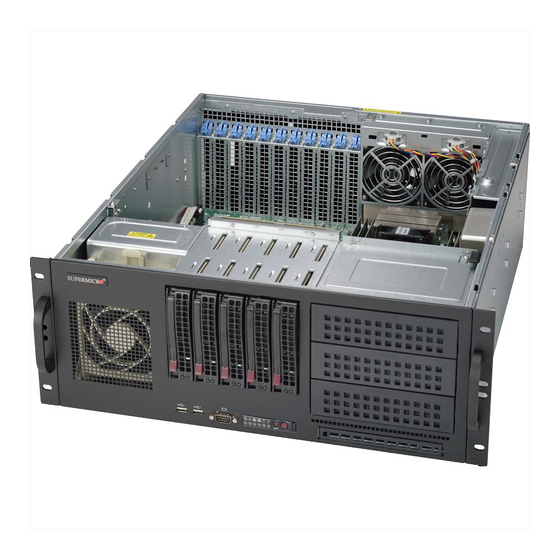
UPER ERVER 6048R-TXR User's Manual Figure 6-1. Front and Rear Chassis Views SATA Drives (5) 5.25" Drive Bays (3) I/O Ports Power Supplies PCI Expansion Slots (11) Control Panel The control panel (located on the front of the chassis) must be connected to the JF1 connector on the serverboard to provide you with system status indications. -
Page 77: Accessing The Inside Of The System
Chapter 6: Advanced Chassis Setup Accessing the Inside of the System Performing maintenance on componenets such as fans requires access to the inside of the server system. Follow the steps below to remove the top/left side cover to gain access to the inside of the 6048R-TXR. If the system has been installed to a rack, carefully pull it out on the rails until the top cover is exposed. -
Page 78: System Fans
UPER ERVER 6048R-TXR User's Manual System Fans The SC842XTQ-R606B chassis includes two rear exhaust fans and one intake fan. It is very important that the chassis covers are properly installed and making a good seal in order for the cooling air to circulate properly through the chassis and cool the components. -
Page 79: Drive Bay Installation/Removal
Chapter 6: Advanced Chassis Setup Drive Bay Installation/Removal Hot-Swap Drive Bays The hot-swappable hard drives are mounted in drive carriers to simplify their installa- tion and removal from the chassis. The chassis supports up to five 3.5" hard drives. These hard drives plug into a backplane that provides power, drive ID and bus ter- mination. - Page 80 UPER ERVER 6048R-TXR User's Manual Removing a Hard Drive from a Carrier 1. Remove the two screws securing the dummy drive to the drive carrier. 2. Lift the dummy drive out of the drive carrier. 3. Place the hard drive carrier on a flat, stable surface such as a desk, table, or work bench.
-
Page 81: Installing A Peripheral Drive
Chapter 6: Advanced Chassis Setup Installing a Peripheral Drive The SC842XTQ-R606B chassis can support a slim DVD-ROM and up to three 5.25" peripheral drives. Release Tab Guide Screws Figure 6-4. Installing the Peripheral Drive Installing a Peripheral Drive 1. Disconnect the chassis from any power source and remove the cover. 2. -
Page 82: Power Supply
The PWR Fail LED will illuminate and remain on until the failed unit has been replaced. Replace- ment units can be ordered directly from Supermicro. The power supply units have a hot-swap capability, meaning you can replace the failed unit without powering down the system. - Page 83 Chapter 6: Advanced Chassis Setup Figure 6-5. Replacing a Power Supply Module Release Button...
- Page 84 UPER ERVER 6048R-TXR User's Manual Notes 6-10...
-
Page 85: Chapter 7 Bios
The configuration data that determines the system parameters may be changed by entering the AMI BIOS setup utility by pressing <F2> at the appropriate time during system boot. Note: For AMI UEFI BIOS Recovery, please refer to the UEFI BIOS Recovery User Guide posted at http://www.supermicro.com/support/manuals/. -
Page 86: Main Setup
UPER ERVER 6048R-TXR User's Manual Starting the Setup Utility Normally, the only visible Power-On Self-Test (POST) routine is the memory test. As the memory is being tested, press the <F2> key to enter the main menu of the AMI BIOS setup utility. From the main menu, you can access the other setup screens. -
Page 87: Advanced Setup Configurations
Chapter 7: BIOS Supermicro X10DRX BIOS Version This item displays the version of the BIOS ROM used in this system. Build Date This item displays the date that the BIOS setup utility was built. Memory Information Total Memory This displays the amount of memory that is available in the system. - Page 88 UPER ERVER 6048R-TXR User's Manual Boot Features Quiet Boot Use this item to select the bootup screen display between POST messages and the OEM logo. Select Disabled to display the POST messages. Select Enabled to display the OEM logo instead of the normal POST messages. The options are Enabled and Disabled.
- Page 89 Chapter 7: BIOS Power Button Function If this feature is set to Instant_Off, the system will power off immediately as soon as the user presses the power button. If this feature is set to 4-Second Override, the system will power off when the user presses the power button for 4 seconds or longer.
- Page 90 UPER ERVER 6048R-TXR User's Manual Clock Spread Spectrum Select Enable to enable Clock Spectrum support, which will allow the BIOS attempt to reduce the level of Electromagnetic Interference caused by the components when needed. The options are Disabled and Enabled. Hyper-Threading (ALL) Select Enable to support Intel Hyper-threading Technology to enhance CPU perfor- mance.
- Page 91 Chapter 7: BIOS If this feature is set to Enable, the DCU (Data Cache Unit) IP prefetcher will prefetch the IP address in advance to improve network connectivity and system performance. The options are Disable and Enable. Direct Cache Access (DCA) Select Enable to use Intel's DCA (Direct Cache Access) technology to improve data transfer efficiency.
- Page 92 UPER ERVER 6048R-TXR User's Manual ing fan-speeds, which might compromise system performance. The fan speeds are controlled by the firmware management via IPMI 2.0. The options are Performance, Balanced Performance, Balanced Power, and Power. Energy Efficiency Turbo Select Enable for Energy Efficiency Turbo support to turn up CPU core frequency to improve CPU performance without compromising energy efficiency.
- Page 93 Chapter 7: BIOS CPU C6 Report Select Enable to allow the BIOS to report the CPU C6 State (ACPI C3) to the operating system. During the CPU C6 State, the power to all cache is turned off. The options are Enable and Disable. Enhanced Halt State (C1E) Select Enable to use Enhanced Halt-State technology, which will significantly reduce CPU power consumption by reducing CPU clock cycle and voltage during...
- Page 94 UPER ERVER 6048R-TXR User's Manual IOU0 (IIO1 PCIe Port 2) This item configures the PCI-E port Bifuraction setting for a PCI-E port specified by the user. The options are x4x4x4x4, x4x4x8, x8x4x4, x8x8, x16, and Auto. CPU1 SLOT1 PCI-E 3.0 x8 Link Speed This item configures the link speed of a PCI-E port specified by the user.
- Page 95 Chapter 7: BIOS This item configures the link speed of a PCI-E port specified by the user. The options are Gen 1 (Generation 1) (2.5 GT/s), Gen 2 (Generation 2) (5 GT/s), and Gen 3 (Generation 3) (8 GT/s). IOU0 (II02 PCIE Port 2) Use this item to configure the PCI-E port Bifuraction setting for a PCI-E port speci- fied by the user.
- Page 96 UPER ERVER 6048R-TXR User's Manual No Snoop Select Enable to support no-snoop mode for each CB device. The options are Disable and Enable. Relaxed Ordering Select Enable to enable Relaxed Ordering support which will allow certain transactions to violate the strict-ordering rules of PCI bus for a transaction to be completed prior to other transactions that have already been enqueued.
- Page 97 Chapter 7: BIOS Link Frequency Select Use this feature to select the desired QPI link frequency. The options are 6.4 GT/s, 8.0 GT/s, 9.6 GT/s, Auto, and Auto Limited. Link L0p Enable Select Enable for the QPI to enter the L0p state for power saving. The options are Disable and Enable.
- Page 98 UPER ERVER 6048R-TXR User's Manual Enable ADR Asynchronous DRAM Refresh (ADR), supported by the Haswell-EP/EN pro- cessors, provides a mechanism to preserve the key data in DDR4 NVDIMM system memory when an AC power-supply failure occurs. The options are ADR + NVDIMMs, ADR + Battery-backed DIMMs, and Disabled.
- Page 99 Chapter 7: BIOS Select Enable to enable memory-sparing support for memory ranks to improve memory performance. The options are Disabled and Enabled. Patrol Scrub Patrol Scrubbing is a process that allows the CPU to correct correctable memory errors detected on a memory module and send the correction to the requestor (the original source).
- Page 100 UPER ERVER 6048R-TXR User's Manual EHCI Hand-Off This item is for operating systems that do not support Enhanced Host Controller Interface (EHCI) hand-off. When this item is enabled, EHCI ownership change will be claimed by the EHCI driver. The settings are Enabled and Disabled. Port 60/64 Emulation Select Enabled for I/O port 60h/64h emulation support, which will provide complete legacy USB keyboard support for the operating systems that do not support legacy...
- Page 101 Chapter 7: BIOS *If the item above "Configure SATA as" is set to AHCI, the following items will display: Support Aggressive Link Power Management When this item is set to Enabled, the SATA AHCI controller manages the power usage of the SATA link. The controller will put the link to a low power state when the I/O is inactive for an extended period of time, and the power state will return to normal when the I/O becomes active.
- Page 102 UPER ERVER 6048R-TXR User's Manual Port 0 ~ Port 5 SATA Device Type (Available when a SATA port is detected) Use this item to specify if the SATA port specified by the user should be con- nected to a Solid State drive or a Hard Disk Drive. The options are Hard Disk Drive and Solid State Drive.
- Page 103 Chapter 7: BIOS Port 0 ~ Port 5 Spin Up Device On an edge detect from 0 to 1, set this item to allow the PCH to start a COMRE- SET initialization to the device. The options are Enabled and Disabled. Port 0 ~ Port 5 SATA Device Type Use this item to specify if the SATA port specified by the user should be con- nected to a Solid State drive or a Hard Disk Drive.
- Page 104 UPER ERVER 6048R-TXR User's Manual sSATA Port 0~ Port 3 Select Enabled to enable an sSATA port specified by the user. The options are Disabled and Enabled. sSATA Port 0 ~ Port 3 Hot Plug Select Enabled to enable hot-plugging support for a port specified by the user, which will allow the user to replace a SATA disk drive installed on this port without shutting down the system.
- Page 105 Chapter 7: BIOS SATA/sSATA RAID Boot Select Select SATA Controller to boot the system from a SATA RAID device. Select sSATA Controller to boot the system from a S-SATA RAID device. Select Both to boot the system either from a SATA RAID device or from an sSATA RAID device. Please note that the option-Both is not supported by the Windows Server 2012/ R2 OS.
- Page 106 UPER ERVER 6048R-TXR User's Manual • ME Firmware Status #1 • ME Firmware Status #2 • Current State • Error Code PCIe/PCI/PnP Configuration The following PCI information will be displayed: PCI Bus Driver Version PCI Devices Common Settings: PCI PERR/SERR Support Select Enabled for the system to log an error event when a PERR (PCI/PCI-E Parity Error) or a SERR (System Error) occurs.
- Page 107 Chapter 7: BIOS Warning: Enabling ASPM support may cause some PCI-E devices to fail! MMIOHBase Use this item to select the base memory size according to memory-address map- ping for the IO hub. The base memory size must be between 4032G to 4078G. The options are 56T, 48T, 24T, 512G, and 256G.
- Page 108 UPER ERVER 6048R-TXR User's Manual Serial Port 1 Configuration/Serial Port 2 Configuration Serial Port 1/Serial Port 2 Select Enabled to enable the onboard serial port specified by the user. The options are Enabled and Disabled. Device Settings This item displays the base I/O port address and the Interrupt Request address of a serial port specified by the user.
- Page 109 Chapter 7: BIOS COM1 Console Redirection Settings Terminal Type This feature allows the user to select the target terminal emulation type for Con- sole Redirection. Select VT100 to use the ASCII Character set. Select VT100+ to add color and function key support. Select ANSI to use the Extended ASCII Char- acter Set.
- Page 110 UPER ERVER 6048R-TXR User's Manual Recorder Mode Select Enabled to capture the data displayed on a terminal and send it as text messages to a remote server. The options are Disabled and Enabled. Resolution 100x31 Select Enabled for extended-terminal resolution support. The options are Dis- abled and Enabled.
- Page 111 Chapter 7: BIOS Select VT-UTF8 to use UTF8 encoding to map Unicode characters into one or more bytes. The options are ANSI, VT100, VT100+, and VT-UTF8. Bits Per second Use this feature to set the transmission speed for a serial port used in Console Redirection.
- Page 112 UPER ERVER 6048R-TXR User's Manual Resolution 100x31 Select Enabled for extended-terminal resolution support. The options are Dis- abled and Enabled. Legacy OS Redirection Resolution Use this feature to select the number of rows and columns used in Console Redirection for legacy OS support. The options are 80x24 and 80x25. Putty KeyPad Use this item to configure the settings for the function keys and the key pad for Putty, which is a terminal emulator designed for the Windows OS.
- Page 113 Chapter 7: BIOS and function key support. Select ANSI to use the extended ASCII character set. Select VT-UTF8 to use UTF8 encoding to map Unicode characters into one or more bytes. The options are ANSI, VT100, VT100+, and VT-UTF8. Bits Per Second This item sets the transmission speed for a serial port used in Console Redirec- tion.
- Page 114 UPER ERVER 6048R-TXR User's Manual Trusted Computing (Available when a TPM device is installed and detected by the BIOS) Configuration Security Device Support If this feature and the TPM jumper on the motherboard are both set to Enabled, onboard security devices will be enabled for TPM support to enhance data integrity and network security.
-
Page 115: Event Logs
Chapter 7: BIOS Event Logs Use this feature to configure Event Log settings. Change SMBIOS Event Log Settings This feature allows the user to configure SMBIOS Event settings. Enabling/Disabling Options SMBIOS Event Log Select Enabled to enable SMBIOS (System Management BIOS) Event Logging during system boot. - Page 116 UPER ERVER 6048R-TXR User's Manual SMBIOS Event Log Standard Settings Log System Boot Event Select Enabled to log system boot events. The options are Disabled and Enabled. MECI (Multiple Event Count Increment) Enter the increment value for the multiple event counter. Enter a number between 1 to 255.
-
Page 117: Ipmi
Chapter 7: BIOS IPMI Use this feature to configure Intelligent Platform Management Interface (IPMI) settings. IPMI Firmware Revision This item indicates the IPMI firmware revision used in your system. IPMI Status This item indicates the status of the IPMI firmware installed in your system. 7-33... - Page 118 UPER ERVER 6048R-TXR User's Manual System Event Log Enabling/Disabling Options SEL Components Select Enabled to enable all system event logging support at bootup. The options are Enabled and Disabled. Erasing Settings Erase SEL Select Yes, On next reset to erase all system event logs upon next system reboot. Select Yes, On every reset to erase all system event logs upon each system reboot.
- Page 119 Chapter 7: BIOS BMC Network Configuration The following items will be displayed: • IPMI LAN Selection • IPMI Network Link Status Update IPMI LAN Configuration Select Yes for the BIOS to automatically reset the following IPMI settings at next system boot.
-
Page 120: Security Settings
UPER ERVER 6048R-TXR User's Manual Security Settings This menu allows the user to configure the following security settings for the system. Password Check Select Setup for the system to prompt for a password at upon entering the BIOS setup utility. Select Always for the system to prompt for a password at bootup and upon entering the BIOS setup utility. - Page 121 Chapter 7: BIOS Secure Boot Menu Secure Boot Select Enable for secure boot support to ensure system security at bootup. The options are Enabled and Disabled. Secure Boot Mode This feature allows the user to select the desired secure boot mode for the system. The options are Standard and Custom.
- Page 122 UPER ERVER 6048R-TXR User's Manual Append KEK (Key Exchange Key) Select <Yes> to load the new KEK from the manufacture defaults. Select <No> to load the new KEK from other sources. Authorized Signatures Delete DB (DataBase) Select <Yes> to confirm deletion of a database from the system. ...
-
Page 123: Boot Settings
Chapter 7: BIOS Boot Settings Use this feature to configure Boot Settings: Boot Configuration Setup Prompt Timeout Use this item to indicate how many seconds the system shall wait for the BIOS setup activation key to respond before the system starts to boot. The default setting is 1. Boot Mode Select Use this item to select the type of device to be used for system boot. - Page 124 UPER ERVER 6048R-TXR User's Manual Delete Boot Option Use this item to select a boot device to delete from the boot priority list. Delete Boot Option Select the target boot device to delete. Network Drive BBS Priorities • Legacy Boot Order #1 7-40...
-
Page 125: Save & Exit
Chapter 7: BIOS Save & Exit Select the Save & Exit tab from the BIOS setup screen to configure the settings below. Discard Changes and Exit Select this option to quit the BIOS setup without making any permanent changes to the system configuration, and reboot the computer. Select Discard Changes and Exit from the Exit menu and press <Enter>. - Page 126 UPER ERVER 6048R-TXR User's Manual Restore Defaults Select Restore Defaults from the Exit menu and press <Enter> to load manufacture default settings for your system to maximize system performance but not stability. Save As User Defaults Select Save as User Defaults from the Exit menu and press <Enter> to save changes to the BIOS setup for future use.
-
Page 127: Appendix A Bios Error Beep Codes
Appendix A: BIOS POST Error Codes Appendix A BIOS Error Beep Codes During the POST (Power-On Self-Test) routines, which are performed at each system boot, errors may occur. Non-fatal errors are those which, in most cases, allow the system to continue to boot. - Page 128 UPER ERVER 6048R-TXR User's Manual Notes...
-
Page 129: Appendix B System Specifications
Appendix B: System Specifications Appendix B System Specifications Processors Two E5-2600 v3 series processors in LGA 2011 sockets (Socket R3) Note: Please refer to our website for a complete listing of supported processors. Chipset Intel C612 chipset BIOS 16 MB AMIBIOS® SPI Flash ROM Memory Capacity Sixteen DIMM slots that can support up to 1024 GB of LRDIMM or 512 GB of RDIMM DDR4-2133/1866/1600 memory... - Page 130 UPER ERVER 6048R-TXR User's Manual Chassis SC842XTQ-R606B (4U rackmount) Dimensions: (WxHxD) 17.2 x 7 x 20.5 in. (437 x 178 x 521 mm) Weight 47 lbs. (21.3 kg.) System Cooling One 9-cm system fan and two 8-cm rear exhaust fans System Input Requirements AC Input Voltage: 100 - 240V AC auto-range Rated Input Current: 7.5-3.5A (100-240V)
- Page 131 Appendix B: System Specifications Notes...
- Page 132 ERVER 6048R-TXR User's Manual (continued from front) The products sold by Supermicro are not intended for and will not be used in life support systems, medical equipment, nuclear facilities or systems, aircraft, aircraft devices, aircraft/emergency com- munication devices or other critical systems whose failure to perform be reasonably expected to result in significant injury or loss of life or catastrophic property damage.
Need help?
Do you have a question about the SuperServer 6048R-TXR and is the answer not in the manual?
Questions and answers