Table of Contents
Advertisement
Quick Links
Advertisement
Table of Contents

Related Manuals for Supermicro SuperServer 6029TR-HTR


Summary of Contents for Supermicro SuperServer 6029TR-HTR
- Page 1 SuperServer ® 6029TR-HTR USER’S MANUAL Revision 1.0b...
- Page 2 State of California, USA. The State of California, County of Santa Clara shall be the exclusive venue for the resolution of any such disputes. Supermicro's total liability for all claims will not exceed the price paid for the hardware product.
- Page 3 About this Manual This manual is written for professional system integrators and PC technicians. It provides information for the installation and use of the SuperServer 6029TR-HTR. Installation and maintenance should be performed by experienced technicians only. Please refer to the 6029TR-HTR server specifications page on our website for updates on supported memory, processors and operating systems (http://www.supermicro.com).
-
Page 4: Table Of Contents
Preface Contents Chapter 1 Introduction 1.1 Overview ..........................8 1.2 Unpacking the System ......................8 1.3 System Features ........................9 1.4 Server Chassis Features ....................10 Control Panel ........................10 Front Features ........................11 Rear Features ........................12 1.5 Motherboard Layout ......................13 Quick Reference Table ......................14 Chapter 2 Server Installation 2.1 Overview ..........................16 2.2 Preparing for Setup ......................16 Choosing a Setup Location ....................16... - Page 5 SuperServer 6029TR-HTR User's Manual Processor and Heatsink Installation ..................25 Attaching the Processor to the Narrow Processor Clip to Create the Processor Package Assembly ...........................26 Attaching the Processor Package Assembly to the Heatsink to Form the Processor Heatsink Module (PHM) ....................27 Preparing the CPU Socket for Installation ................28...
- Page 6 Preface Rear I/O Ports ........................52 4.3 Jumpers ..........................54 Explanation of Jumpers ....................54 4.4 LED Indicators ........................56 Chapter 5 Software 5.1 Microsoft Windows OS Installation ..................58 5.2 Driver Installation ........................60 5.3 SuperDoctor 5 ........................61 ® 5.4 IPMI ............................62 Chapter 6 BIOS 6.1 Introduction .........................63 6.2 Main Setup .........................64 6.3 Advanced Setup Configurations ..................66...
- Page 7 SuperServer 6029TR-HTR User's Manual Contacting Supermicro Headquarters Address: Super Micro Computer, Inc. 980 Rock Ave. San Jose, CA 95131 U.S.A. Tel: +1 (408) 503-8000 Fax: +1 (408) 503-8008 Email: marketing@supermicro.com (General Information) support@supermicro.com (Technical Support) Website: www.supermicro.com Europe Address: Super Micro Computer B.V.
-
Page 8: Overview
HDD Backplane BPN-ADP-6SATA3M2-1UL 1.2 Unpacking the System Inspect the box the SuperServer 6029TR-HTR was shipped in and note if it was damaged in any way. If any equipment appears damaged, please file a damage claim with the carrier who delivered it. -
Page 9: System Features
Chapter 1: Introduction 1.3 System Features The following table provides you with an overview of the main features of the 6029TR-HTR. Please refer to Appendix B for additional specifications. System Features Motherboard X11DPT-L Chassis SC827HQ-R1K68BP3 Dual Intel Xeon 81xx/61xx/51xx/41xx/31xx series or 82xx/62xx/52xx/42xx/32xx series processors (support for CPUs with a TDP of 70-140W) Socket Type Dual Socket P (LGA 3647) -
Page 10: Server Chassis Features
SuperServer 6029TR-HTR User's Manual 1.4 Server Chassis Features Control Panel The switches and LEDs located on the control panel are described below. See Chapter 4 for details on the control panel connections. Figure 1-1. Control Panel View Control Panel Features... -
Page 11: Front Features
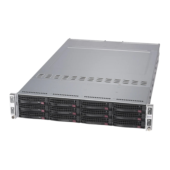
Chapter 1: Introduction Front Features The SC827HQ-R1K68BP3 is a 2U chassis. See the illustration below for the features included on the front of the chassis. Figure 1-2. Chassis Front View Front Chassis Features Item Feature Description Control Panel Front control panel with LEDs and buttons (see preceding page) HDD LED Indicates activity on a hard drive when flashing. -
Page 12: Rear Features
SuperServer 6029TR-HTR User's Manual Rear Features The illustration below shows the features included on the rear of the chassis. Figure 1-3. Chassis Rear View Rear Chassis Features Item Feature Description PCIe 3.0 Slot PCIe 3.0 x16 LP Slot (CPU 1) -
Page 13: Motherboard Layout
Chapter 1: Introduction 1.5 Motherboard Layout Below is a layout of the X11DPT-L with jumper, connector and LED locations shown. See the table on the following page for descriptions. For detailed descriptions, pinout information and jumper settings, refer to Chapter 4. LAN2 LAN1 IPMI_LAN... -
Page 14: Quick Reference Table
IPMI_LAN Dedicated IPMI LAN port I-SATA0-5 SATA 3.0 connection header supported by the Intel® PCH I-SATA Ports with built-in power pins and with support of Supermicro SuperDOM (Disk On Module) I-SATA6/I-SATA7 devices Front Panel Control Signals and Power Input Connector... - Page 15 Chapter 1: Introduction VCCP0 VCCP1 VR13 VR13 4+1 PHASE 4+1 PHASE VPP_AB (2.575) 140W 140W VDDQ_AB (1.2) 10.4 GT VTT_M_AB (0.6) CPU 1 CPU 2 DMI3 DMI3 SLOT1 PCI-E x16 G3 SXB2 PCI-E x4 G3 UPLINK DMI3 #0~#5 SATA x1 G3 #8(Flexible IO) 6.0 Gb/S I-SATA...
-
Page 16: Chapter 2 Server Installation
SuperServer 6029TR-HTR User's Manual Chapter 2 Server Installation 2.1 Overview This chapter provides advice and instructions for mounting your system in a server rack. If your system is not already fully integrated with processors, system memory etc., refer to Chapter 3 for details on installing those specific components. -
Page 17: Server Precautions
Chapter 2: Server Installation • In single rack installations, stabilizers should be attached to the rack. In multiple rack in- stallations, the racks should be coupled together. • Always make sure the rack is stable before extending a server or other component from the rack. -
Page 18: Circuit Overloading
SuperServer 6029TR-HTR User's Manual Circuit Overloading Consideration should be given to the connection of the equipment to the power supply circuitry and the effect that any possible overloading of circuits might have on overcurrent protection and power supply wiring. Appropriate consideration of equipment nameplate ratings should be used when addressing this concern. -
Page 19: Installing The Rails
Chapter 2: Server Installation 2.3 Installing the Rails There are a variety of rack units on the market, which may require a slightly different assembly procedure. The following is a basic guideline for installing the system into a rack with the rack mounting hardware provided. -
Page 20: Installing The Chassis Rails
SuperServer 6029TR-HTR User's Manual Installing the Chassis Rails Begin the rack mounting procedure by installing the inner rails to the server chassis. 1. Position the front and rear chassis rail sections along the side of the server making sure the screw holes line up. Note that these two rails are left/right specific. -
Page 21: Outer Rack Rails
Chapter 2: Server Installation Outer Rack Rails Outer rails attach to the rack and hold the chassis in place. The outer rails for the SC827 chassis extend between 30 inches and 33 inches. Installing the Outer Rails to the Rack 1. -
Page 22: Installing The Rack Rails
SuperServer 6029TR-HTR User's Manual Installing the Rack Rails Determine where you want to place the server in the rack (see the Rack and Server Precautions in Section 2.2). Note that servers should always be installed to the bottom of a rack first for stability reasons. -
Page 23: Installing The Server Into A Telco Rack
Chapter 2: Server Installation Installing the Server into a Telco Rack To install the SuperServer 6029TR-HTR into a Telco (or “open”) type rack, use two L-shaped brackets on either side of the chassis (four total). 1. First, determine how far the server will extend out from the front of the rack. The chassis should be positioned so that the weight is balanced between front and back. -
Page 24: Chapter 3 Maintenance And Component Installation
SuperServer 6029TR-HTR User's Manual Chapter 3 Maintenance and Component Installation This chapter provides instructions on installing and replacing main system components. To prevent compatibility issues, only use components that match the specifications and/or part numbers given. Installation or replacement of most components require that power first be removed from the system. -
Page 25: Motherboard Components
When receiving a motherboard without a processor pre-installed, make sure that the plastic CPU socket cap is in place and none of the socket pins are bent; otherwise, contact your retailer immediately. • Refer to the Supermicro website for updates on CPU support. -
Page 26: Attaching The Processor To The Narrow Processor Clip To Create The Processor Package Assembly
SuperServer 6029TR-HTR User's Manual Attaching the Processor to the Narrow Processor Clip to Create the Processor Package Assembly To properly install the CPU into the narrow processor clip, please follow the steps below. 1. Locate pin 1 (notch A), which is the triangle located on the top of the narrow processor clip. -
Page 27: Attaching The Processor Package Assembly To The Heatsink To Form The Processor Heatsink Module (Phm)
Chapter 3: Maintenance and Component Installation Attaching the Processor Package Assembly to the Heatsink to Form the Processor Heatsink Module (PHM) After you have made a processor package assembly by following the instructions on the previous page, please follow the steps below to mount the processor package assembly onto the heatsink to create the Processor Heatsink Module (PHM). -
Page 28: Preparing The Cpu Socket For Installation
SuperServer 6029TR-HTR User's Manual Preparing the CPU Socket for Installation This motherboard comes with the CPU socket pre-assembled in the factory. The CPU socket contains 1) a dust cover, 2) a socket bracket, 3) the CPU socket, and 4) a back plate. These components are pre-installed on the motherboard before shipping. -
Page 29: Installing The Processor Heatsink Module (Phm)
Chapter 3: Maintenance and Component Installation Installing the Processor Heatsink Module (PHM) Once you have assembled the processor heatsink module (PHM), you are ready to install the processor heatsink module (PHM) into the CPU socket on the motherboard. Note that there are two heatsink models. -
Page 30: Removing The Processor Heatsink Module (Phm) From The Motherboard
SuperServer 6029TR-HTR User's Manual Removing the Processor Heatsink Module (PHM) from the Motherboard Before removing the processor heatsink module (PHM), unplug power cord from the power outlet. 1. Using a T30 Torx-bit screwdriver, turn the screws on the PHM counterclockwise to loosen them from the socket, starting with screw marked #4 (in the sequence of 4, 3, 2, 2. -
Page 31: Pci Expansion Card Installation
Chapter 3: Maintenance and Component Installation PCI Expansion Card Installation The system includes a pre-installed riser card (p/n RSC-R1UTP-E16R) that positions one PCIe card at a 90 degree angle, allowing it to fit inside the chassis. Installing PCI Expansion Cards The riser card has already been pre-installed into the motherboard. -
Page 32: Memory Installation
Check the Supermicro website for possible updates to memory support. Note: 2933 MHz memory is supported by the 82xx/62xx platform only. - Page 33 Chapter 3: Maintenance and Component Installation • For each individual population, rearrangements between channels are allowed as long as the resulting population is compliant with the PDG rules for the 82xx/62xx/52xx platform. • For each individual population, please use the same DDR4 DIMM in all slots as specified by the PDG rules.
-
Page 34: Dimm Installation
SuperServer 6029TR-HTR User's Manual DIMM Installation COM1 LAN2 LAN1 IPMI_LAN 1. Insert DIMM modules in the following USB0/1(3.0) CTRL CTRL LEDM1 order: P1-DIMMA1, P1-DIMMD1, P1- JSD1 DIMMB1, and P1-DIMME1. For the system JTPM1 I-SATA6 JBT1 to work properly, please use memory... -
Page 35: Motherboard Battery
Chapter 3: Maintenance and Component Installation Motherboard Battery The motherboard uses non-volatile memory to retain system information when system power is removed. This memory is powered by a lithium battery residing on the motherboard. Replacing the Battery Begin by removing power from the system as described in Section 3.1. 1. -
Page 36: Chassis Components
SuperServer 6029TR-HTR User's Manual 3.4 Chassis Components Front Bezel If your system has an optional bezel attached to the front of the chassis, you will need to remove it to gain access to the drive bays. 1. Unlock the front of the chassis and then press the release knob. -
Page 37: Hard Drive Carrier Indicators
Chapter 3: Maintenance and Component Installation Removing a Drive from a Drive Carrier 1. Remove the screws that secure the hard drive to the carrier and separate the hard drive from the carrier. Replace the carrier back into the drive bay. Figure 3-3. -
Page 38: System Cooling
SuperServer 6029TR-HTR User's Manual System Cooling Four 8-cm counter-rotating fans provide the cooling for the system. Each fan unit is actually made up of two fans joined back-to-back, which rotate in opposite directions. This counter- rotating action generates exceptional airflow and is effective in dampening vibration levels. - Page 39 Chapter 3: Maintenance and Component Installation 5. Lift the cover from the chassis. 6. Remove the failed fan's wiring from the fan header on the motherboard. 7. Lift the failed fan from the chassis and pull it completely out. 8. Place the new fan into the vacant space in the housing while making sure the arrows on the top of the fan (indicating air direction) point in the same direction as the arrows on the other fans.
- Page 40 SuperServer 6029TR-HTR User's Manual Figure 3-6. Replacing a System Fan in the Fan Housing...
-
Page 41: Backplane
Chapter 3: Maintenance and Component Installation Backplane The SC827HQ chassis backplane is located behind the hard drives and in front of the front system fans. If it is necessary to remove the backplane, follow the instructions below. Removing the Backplane 1. - Page 42 SuperServer 6029TR-HTR User's Manual 7. Loosen the six screws in the backplane mounting bracket, located on the floor of the chassis. Figure 3-8. Loosening the Backplane Mounting Bracket in the Floor of the Chassis 8. Gently ease the backplane up and out of the chassis at a slight angle.
-
Page 43: Installing The Backplane
Chapter 3: Maintenance and Component Installation Installing the Backplane 1. Ensure that all of the hard drive trays have been removed from the bays in the front of the chassis. 2. Secure the side mounting bracket to the backplane with the six screws provided. 3. -
Page 44: Air Shroud
SuperServer 6029TR-HTR User's Manual Air Shroud The air shroud is used to concentrate airflow to maximize fan efficiency. The air shroud requires to be fixed with screws. Installing the Air Shroud 1. Lay the chassis on a flat, stable surface and remove the chassis cover. -
Page 45: I/O Shield
Chapter 3: Maintenance and Component Installation I/O Shield The I/O shield holds the serverboard ports in place. The I/O shield does not require installation. Node Installation/Removal As with any server system, power must be removed from the serverboard when upgrading or installing memory or processors. - Page 46 SuperServer 6029TR-HTR User's Manual Installing the Serverboard 1. Review the documentation that came with your serverboard. Become familiar with component placement, requirements, precautions, and cable connections. 2. Pull the serverboard node drawer out of the back of the chassis. 3. Remove the expander card brackets: a.
- Page 47 Chapter 3: Maintenance and Component Installation Figure 3-12. Installing the Serverboard in the Serverboard Node Drawer...
-
Page 48: Expansion Card/Expansion Slot
SuperServer 6029TR-HTR User's Manual Expansion Card/Expansion Slot The 6029TR-HTR includes one preinstalled riser card per node, designed specifically for use in a 2U rackmount chassis. This riser card (RSC-R1UTP-E16R) supports one low-profile PCI Express x16 card for each node. Installing the Riser Card onto the Riser Card Bracket 1. -
Page 49: Power Supply
2. Push the colored release tab to the side and pull the power module out with the handle provided. 3. Replace the failed power supply module with the exact same model from Supermicro. 4. Carefully insert the new module into position in the chassis and push it in until fully seated. -
Page 50: Headers And Connectors
SuperServer 6029TR-HTR User's Manual Chapter 4 Motherboard Connections This section describes the connections on the motherboard and provides pinout definitions. Note that depending on how the system is configured, not all connections are required. The LEDs on the motherboard are also described here. A motherboard layout indicating component locations may be found in Chapter 1. - Page 51 SATA7 can be used with Supermicro SuperDOMs which are yellow SATA DOM connectors with power pins built in, and do not require external power cables. Supermicro SuperDOMs are backward-compatible with regular SATA HDDs or SATA DOMs that need external power...
-
Page 52: Ports
SuperServer 6029TR-HTR User's Manual 4.2 Ports Rear I/O Ports See the figure below for the locations and descriptions of the various I/O ports on the rear of the motherboard. Back Panel I/O Ports Description No. Description No. Description USB 0 (USB 3.0) LAN1 USB 1 (USB 3.0) - Page 53 (Note: UID can also be triggered via IPMI on the motherboard. For more information, please refer to the IPMI User's Guide posted on our website at http://www.supermicro.com.) UID Switch...
-
Page 54: Jumpers
SuperServer 6029TR-HTR User's Manual 4.3 Jumpers Explanation of Jumpers To modify the operation of the motherboard, jumpers are used to choose between optional settings. Jumpers create shorts between two pins to change the function associated with it. Pin 1 is identified with a square solder pad on the printed circuit board. See the motherboard layout page for jumper locations. - Page 55 Chapter 4: Motherboard Connections Manufacturing Mode Select Close JPME2 to bypass SPI flash security and force the system to use the Manufacturing Mode, which will allow you to flash the system firmware from a host server to modify system settings. See the table below for jumper settings. Manufacturing Mode Select Jumper Settings Jumper Setting...
-
Page 56: Led Indicators
SuperServer 6029TR-HTR User's Manual 4.4 LED Indicators Dedicated IPMI LAN LEDs A dedicated IPMI LAN is located on the I/O back panel of the motherboard. The amber LED on the right indicates activity, while the green LED on the left indicates the speed of the connection. - Page 57 Chapter 4: Motherboard Connections BMC Heartbeat LED LEDM1 is the BMC heartbeat LED. When the LED is blinking green, BMC is functioning normally. See the table below for the LED status. BMC Heartbeat LED Indicator LED Color Definition Green: BMC Normal Blinking Unit ID LED A rear UID LED indicator at LE1 is located near the UID switch on the I/O back panel.
-
Page 58: Chapter 5 Software
USB/SATA DVD drive, or a USB flash drive, or the IPMI KVM console. 2. Retrieve the proper RST/RSTe driver. Go to the Supermicro web page for your motherboard and click on "Download the Latest Drivers and Utilities", select the proper driver, and copy it to a USB flash drive. - Page 59 Chapter 5: Software 4. During Windows Setup, continue to the dialog where you select the drives on which to install Windows. If the disk you want to use is not listed, click on “Load driver” link at the bottom left corner. Figure 5-2.
-
Page 60: Driver Installation
The Supermicro website contains drivers and utilities for your system at https://www. supermicro.com/wdl/. Some of these must be installed, such as the chipset driver. After accessing the website, go into the CDR_Images (in the parent directory of the above link) and locate the ISO file for your motherboard. Download this file to a USB flash drive or a DVD. -
Page 61: Superdoctor ® 5
5.3 SuperDoctor ® The Supermicro SuperDoctor 5 is a program that functions in a command-line or web-based interface for Windows and Linux operating systems. The program monitors such system health information as CPU temperature, system voltages, system power consumption, fan speed, and provides alerts via email or Simple Network Management Protocol (SNMP). -
Page 62: Ipmi
SuperServer 6029TR-HTR User's Manual 5.4 IPMI The X11DPT-L supports the Intelligent Platform Management Interface (IPMI). IPMI is used to provide remote access, monitoring and management. There are several BIOS settings that are related to IPMI. For general documentation and information on IPMI, please visit our website at:... -
Page 63: Chapter 6 Bios
Chapter 6: BIOS Chapter 6 BIOS 6.1 Introduction This chapter describes the AMIBIOS™ Setup utility for the motherboard. The BIOS is stored on a chip and can be easily upgraded using a flash program. Note: Due to periodic changes to the BIOS, some settings may have been added or deleted and might not yet be recorded in this manual. -
Page 64: Main Setup
SuperServer 6029TR-HTR User's Manual 6.2 Main Setup When you first enter the AMI BIOS setup utility, you will enter the Main setup screen. You can always return to the Main setup screen by selecting the Main tab on the top of the screen. The Main BIOS setup screen is shown below. - Page 65 Chapter 6: BIOS CPLD Version This item displays the version of the CPLD (Complex-Programmable Logical Device) used in the system. Memory Information Total Memory This item displays the total size of memory available in the system.
-
Page 66: Advanced Setup Configurations
SuperServer 6029TR-HTR User's Manual 6.3 Advanced Setup Configurations Use the arrow keys to select Boot Setup and press <Enter> to access the submenu items. Warning: Take caution when changing the Advanced settings. An incorrect value, a very high DRAM frequency, or an incorrect DRAM timing setting may make the system unstable. When this occurs, revert to the default to the manufacture default settings. - Page 67 Chapter 6: BIOS Wait For "F1" If Error Use this feature to force the system to wait until the 'F1' key is pressed if an error occurs. The options are Disabled and Enabled. INT19 (Interrupt 19) Trap Response Interrupt 19 is the software interrupt that handles the boot disk function. When this item is set to Immediate, the ROM BIOS of the host adaptors will "capture"...
- Page 68 SuperServer 6029TR-HTR User's Manual Power Button Function This feature controls how the system shuts down when the power button is pressed. Select 4 Seconds Override for the user to power off the system after pressing and holding the power button for 4 seconds or longer. Select Instant Off to instantly power off the system as soon as the user presses the power button.
- Page 69 Chapter 6: BIOS Cores Enabled Use this feature to enable or disable CPU cores in the processor specified by the user. The default setting is 0. Monitor/Mwait Streaming SIMD Extensions 3 (SSE3) includes Monitor and Mwait instructions, which are used for thread synchronization.
- Page 70 SuperServer 6029TR-HTR User's Manual LLC Prefetch If this feature is set to Enabled, the hardware prefetcher will prefetch streams of data and instructions from the main memory to the L3 cache to improve CPU performance. The options are Disable and Enable.
- Page 71 Chapter 6: BIOS Link L0p Enable Select Enable for Link L0p support. The options are Disable, Enable, and Auto. Link L1 Enable Select Enable for Link L1 support. The options are Disable, Enable, and Auto. IO Directory Cache (IODC) IO Directory Cache is an 8-entry cache that stores the directory state of remote IIO writes and memory lookups, and saves directory updates.
- Page 72 SuperServer 6029TR-HTR User's Manual Memory Configuration Integrated Memory Controller (IMC) Enforce POR Select Enable to enforce POR restrictions on DDR4 frequency and voltage programming. The options are POR and Disable. PPR Type Post Package Repair (PPR) is a new feature available on the DDR4 Technology. PPR provides additional spare capacity within a DDR4 DRAM module to be used to replace faulty cell areas detected during system boot.
- Page 73 Chapter 6: BIOS Memory Topology This feature displays DIMM population information. P1 DIMMA1: 2934MT/S Micron SRx4 16GB RDIMM P1 DIMMB1: 2934MT/S Micron SRx4 16GB RDIMM P1 DIMMD1: 2934MT/S Micron SRx4 16GB RDIMM P1 DIMME1: 2934MT/S Micron SRx4 16GB RDIMM P2 DIMMA1: 2934MT/S Micron SRx4 16GB RDIMM P2 DIMMB1: 2934MT/S Micron SRx4 16GB RDIMM P2 DIMMD1: 2934MT/S Micron SRx4 16GB RDIMM P2 DIMME1: 2934MT/S Micron SRx4 16GB RDIMM...
- Page 74 SuperServer 6029TR-HTR User's Manual SDDC Plus One Single Device Data Correction (SDDC) organizes data in a single bundle (x4/x8 DRAM). If any or all the bits become corrupted, corrections occur. The x4 condition is corrected on all cases. The x8 condition is corrected only if the system is in Lockstep Mode. The options are Disable and Enable.
- Page 75 Chapter 6: BIOS Link Speed Use this feature to select the link speed for the PCI-E port specified by the user. The options are Auto, Gen 1 (2.5 GT/s), Gen 2 (5 GT/s), and Gen 3 (8 GT/s). PCI-E Port Link Status This feature displays current PCI-E Link Status.
- Page 76 SuperServer 6029TR-HTR User's Manual IOAT Configuration Disable TPH Transparent Hugepages is a Linux memory management system that enables com- munication in larger blocks (pages). Enabling this feature will increase performance. The options are No and Yes. Prioritize TPH Use this feature to enable Prioritize TPH support. The options are Enable and Disable.
- Page 77 Chapter 6: BIOS Intel® VMD Technology This section describes the configuration settings for the Intel® Volume Management Device (VMD) Technology. Note: After you’ve enabled VMD on a PCI-E slot of your choice, this PCI-E slot will be dedicated for VMD use only, and it will no longer support any PCI-E device. To re- activate this slot for PCI-E use, please disable VMD.
- Page 78 SuperServer 6029TR-HTR User's Manual Hot Plug Capable (Available when the device is detected by the system) Use this feature to enable hot plug support for PCIe root ports 2A~2D. The options are Disable and Enable. VMD Config for PStack2 Intel® VMD for Volume Management Device Select Enable to use the Intel Volume Management Device Technology for this stack.
- Page 79 Chapter 6: BIOS II0-PCIE Express Global Options PCI-E Completion Timeout Disable Use this feature to enable PCI-E Completion Timeout support for electric tuning. The options are Yes, No, and Per-Port. South Bridge USB Module Version This feature display current USB module version. USB Devices This feature display current USB device.
- Page 80 SuperServer 6029TR-HTR User's Manual • ME Firmware Status #2 • Current State • Error Code PCH SATA Configuration When this submenu is selected, the AMI BIOS automatically detects the presence of the SATA devices that are supported by the Intel PCH chip and displays the following items: SATA Controller This item enables or disables the onboard SATA controller supported by the Intel PCH chip.
- Page 81 Chapter 6: BIOS Port 0 ~ Port 7 Hot Plug Set this item to Enabled for hot-plugging support, which will allow the user to replace a SATA drive without shutting down the system. The options are Disabled and Enabled. Port 0 ~ Port 7 Spin Up Device On an edge detect from 0 to 1, set this item to allow the PCH to initialize the device.
- Page 82 SuperServer 6029TR-HTR User's Manual Above 4G Decoding (Available if the system supports 64-bit PCI decoding) Select Enabled to decode a PCI device that supports 64-bit in the space above 4G Address. The options are Disabled and Enabled. SR-IOV Support Use this feature to enable or disable Single Root IO Virtualization Support. The options are Disabled and Enabled.
- Page 83 Chapter 6: BIOS Select Enabled to enable Option ROM support to boot the computer using a device installed on the slot specified by the user. The options are Disabled, Legacy and EFI. Use this feature to select which firmware type to be loaded for the add-on card in this slot. The options are Disabled, Legacy, and EFI.
- Page 84 SuperServer 6029TR-HTR User's Manual IPv4 HTTP Support Select Enabled to enable IPv4 HTTP boot support. The options are Disabled and Enabled. IPv6 PXE Support Select Enabled to enable IPv6 PXE boot support. The options are Disabled and Enabled. IPv6 HTTP Support Select Enabled to enable IPv6 HTTP boot support.
- Page 85 Chapter 6: BIOS SOL Configuration This submenu allows the user to configure the settings of Serial Port 2. Select Enabled to enable the selected onboard serial port. The options are Disabled and Enabled. Device Settings This item displays the status of a serial part specified by the user. Change Settings This feature specifies the base I/O port address and the Interrupt Request address of a serial port specified by the user.
- Page 86 SuperServer 6029TR-HTR User's Manual Bits per second Use this feature to set the transmission speed for a serial port used in Console Redirection. Make sure that the same speed is used in the host computer and the client computer. A lower transmission speed may be required for long and busy lines.
- Page 87 Chapter 6: BIOS Putty KeyPad This feature selects the settings for Function Keys and KeyPad used for Putty, which is a terminal emulator designed for the Windows OS. The options are VT100, LINUX, XTERMR6, SC0, ESCN, and VT400. Redirection After BIOS POST Use this feature to enable or disable legacy console redirection after BIOS POST.
- Page 88 SuperServer 6029TR-HTR User's Manual Parity A parity bit can be sent along with regular data bits to detect data transmission errors. Select Even if the parity bit is set to 0, and the number of 1's in data bits is even. Select Odd if the parity bit is set to 0, and the number of 1's in data bits is odd.
- Page 89 Chapter 6: BIOS Legacy Console Redirection Legacy Serial Redirection Port Use this feature to select a COM port to display redirection of Legacy OS and Legacy OPROM messages. The options are COM1 and SOL. Serial Port for Out-of-Band Management/Windows Emergency Management Services (EMS) The submenu allows the user to configure Console Redirection settings to support Out-of- Band Serial Port management.
- Page 90 SuperServer 6029TR-HTR User's Manual Flow Control Use this item to set the flow control for Console Redirection to prevent data loss caused by buffer overflow. Send a "Stop" signal to stop sending data when the receiving buffer is full. Send a "Start" signal to start sending data when the receiving buffer is empty. The options are None, Hardware RTS/CTS, and Software Xon/Xoff.
- Page 91 Chapter 6: BIOS Security Device Support If this feature and the TPM jumper (JPT1) on the motherboard are both enabled, the onboard security (TPM) device will be enabled in the BIOS to enhance data integrity and system security. Please note that the OS will not show the security device. Neither TCG EFI protocol nor INT1A interaction will be made available for use.
- Page 92 SuperServer 6029TR-HTR User's Manual PH (Platform Hierarchy) Randomization (for TPM Version 2.0 and above) Select Enabled for Platform Hierarchy Randomization support, which is used only during the platform developmental stage. This feature cannot be enabled in the production platforms. The options are Disabled and Enabled.
- Page 93 Chapter 6: BIOS Blink LEDs Use this feature to identify the physical network port by blinking the associated LED. Use the keybaord to select a value. UEFI Driver This item displays the UEFI driver version. Adapter PBA This item displays the Processor Bus Adapter (PBA) model number. The PBA number is a nine digit number (i.e., 010B00-000) located near the serial number.
-
Page 94: Event Logs
SuperServer 6029TR-HTR User's Manual 6.4 Event Logs Use this feature to configure Event Log settings. Change SMBIOS Event Log Settings Enabling/Disabling Options SMBIOS Event Log Change this item to enable or disable all features of the SMBIOS Event Logging during system boot. - Page 95 Chapter 6: BIOS SMBIOS Event Long Standard Settings Log System Boot Event This option toggles the System Boot Event logging to enabled or disabled. The options are Enabled and Disabled. MECI The Multiple Event Count Increment (MECI) counter counts the number of occurences that a duplicate event must happen before the MECI counter is incremented.
-
Page 96: Ipmi
SuperServer 6029TR-HTR User's Manual 6.5 IPMI Use this feature to configure Intelligent Platform Management Interface (IPMI) settings. BMC Firmware Revision This item indicates the IPMI firmware revision used in your system. IPMI STATUS (Baseboard Management Controller) This item indicates the status of the IPMI firmware installed in your system. - Page 97 Chapter 6: BIOS When SEL is Full This feature allows the user to decide what the BIOS should do when the system event log is full. Select Erase Immediately to erase all events in the log when the system event log is full.
- Page 98 SuperServer 6029TR-HTR User's Manual Gateway IP Address This item displays the Gateway IP address for this computer. This should be in decimal and in dotted quad form (i.e., 10.135.0.250). VLAN This item displays the virtual LAN settings. The options are Disable and Enable.
-
Page 99: Security
Chapter 6: BIOS 6.6 Security This menu allows the user to configure the following security settings for the system. Administrator Password Press <Enter> to create a new, or change an existing, Administrator password. User Password Press <Enter> to create a new, or change an existing, user password. Administrator Password Password Check Select Setup for the system to check for a password at Setup. - Page 100 SuperServer 6029TR-HTR User's Manual Secure Boot This section displays the contents of the following secure boot features: • System Mode • Secure Boot • Vendor Keys Secure Boot Use this item to enable secure boot. The options are Disabled and Enabled.
- Page 101 Chapter 6: BIOS Authorized Signatures This feature allows the user to configure the settings of the Authorized Signatures. The options are Set New and Append. Forbidden Signatures This feature allows the user to configure the settings of the Forbidden Signatures. The options are Set New and Append.
-
Page 102: Boot
SuperServer 6029TR-HTR User's Manual 6.7 Boot Use this feature to configure Boot Settings: Boot Mode Select Use this item to select the type of device that the system is going to boot from. The options are Legacy, UEFI, and Dual. The default setting is Dual. - Page 103 Chapter 6: BIOS • Legacy/UEFI/Dual/Boot Option #6 • Legacy/UEFI/Dual/Boot Option #7 • Legacy/UEFI/Dual/Boot Option #8 • UEFI/Dual/Boot Option #9 • Dual/Boot Option #10 • Dual/Boot Option #11 • Dual/Boot Option #12 • Dual/Boot Option #13 • Dual/Boot Option #14 • Dual/Boot Option #15 •...
- Page 104 SuperServer 6029TR-HTR User's Manual UEFI Boot Option #3 The options are ISATA P0:HGST HUH728080ALE600 (SATA,Port:0), ISATA P1:HGST HUH728080ALE600 (SATA,Port:1), ISATA P2:HGST HUH728080ALE600 (SATA,Port:2), ISATA P3:HGST HUH728080ALE600 (SATA,Port:3), ISATA P4:HGST HUH728080ALE600 (SATA,Port:4), ISATA P5:HGST HUH728080ALE600 (SATA,Port:5), and Disabled. UEFI Boot Option #4...
-
Page 105: Save & Exit
Chapter 6: BIOS 6.8 Save & Exit Select the Exit tab from the BIOS setup utility screen to enter the Exit BIOS Setup screen. Save Options Discard Changes and Exit Select this option to quit the BIOS Setup without making any permanent changes to the system configuration, and reboot the computer. - Page 106 SuperServer 6029TR-HTR User's Manual Default Options Restore Optimized Defaults To set this feature, select Restore Defaults from the Save & Exit menu and press <Enter>. These are factory settings designed for maximum system stability, but not for maximum performance. Save As User Defaults To set this feature, select Save as User Defaults from the Save &...
-
Page 107: Appendix A Standardized Warning Statements For Ac Systems
Supermicro's Technical Support department for assistance. Only certified technicians should attempt to install or configure components. Read this appendix in its entirety before installing or configuring components in the Supermicro chassis. These warnings may also be found on our website at http://www.supermicro.com/about/... - Page 108 Appendix A: Standardized Warning Statements Warnung WICHTIGE SICHERHEITSHINWEISE Dieses Warnsymbol bedeutet Gefahr. Sie befinden sich in einer Situation, die zu Verletzungen führen kann. Machen Sie sich vor der Arbeit mit Geräten mit den Gefahren elektrischer Schaltungen und den üblichen Verfahren zur Vorbeugung vor Unfällen vertraut. Suchen Sie mit der am Ende jeder Warnung angegebenen Anweisungsnummer nach der jeweiligen Übersetzung in den übersetzten Sicherheitshinweisen, die zusammen mit diesem Gerät ausgeliefert wurden.
- Page 109 SuperServer 6029TR-HTR User's Manual . ٌ ا ك ً ف حالة و ٌ يك أى تتسبب ف اصابة جسذ ة ٌ هذا الزهز ع ٌ خطز !تحذ ز قبل أى تعول عىل أي هعذات،يك عىل علن بالوخاطز ال ا ٌجوة عي الذوائز...
- Page 110 Appendix A: Standardized Warning Statements Warnung Vor dem Anschließen des Systems an die Stromquelle die Installationsanweisungen lesen. ¡Advertencia! Lea las instrucciones de instalación antes de conectar el sistema a la red de alimentación. Attention Avant de brancher le système sur la source d'alimentation, consulter les directives d'installation. .יש...
- Page 111 SuperServer 6029TR-HTR User's Manual Warnung Dieses Produkt ist darauf angewiesen, dass im Gebäude ein Kurzschluss- bzw. Überstromschutz installiert ist. Stellen Sie sicher, dass der Nennwert der Schutzvorrichtung nicht mehr als: 250 V, 20 A beträgt. ¡Advertencia! Este equipo utiliza el sistema de protección contra cortocircuitos (o sobrecorrientes) del edificio.
- Page 112 Appendix A: Standardized Warning Statements Power Disconnection Warning Warning! The system must be disconnected from all sources of power and the power cord removed from the power supply module(s) before accessing the chassis interior to install or remove system components. 電源切断の警告...
- Page 113 SuperServer 6029TR-HTR User's Manual يجب فصم اننظاو من جميع مصادر انطاقت وإ ز انت سهك انكهرباء من وحدة امداد انطاقت قبم انىصىل إىن امنناطق انداخهيت نههيكم نتثبيج أو إ ز انت مكىناث الجهاز 경고! 시스템에 부품들을 장착하거나 제거하기 위해서는 섀시 내부에 접근하기 전에 반드시 전원...
- Page 114 Appendix A: Standardized Warning Statements Attention Il est vivement recommandé de confier l'installation, le remplacement et la maintenance de ces équipements à des personnels qualifiés et expérimentés. !אזהרה .צוות מוסמך בלבד רשאי להתקין, להחליף את הציוד או לתת שירות עבור הציוד واملدربيه...
- Page 115 SuperServer 6029TR-HTR User's Manual Warnung Diese Einheit ist zur Installation in Bereichen mit beschränktem Zutritt vorgesehen. Der Zutritt zu derartigen Bereichen ist nur mit einem Spezialwerkzeug, Schloss und Schlüssel oder einer sonstigen Sicherheitsvorkehrung möglich. ¡Advertencia! Esta unidad ha sido diseñada para instalación en áreas de acceso restringido. Sólo puede obtenerse acceso a una de estas áreas mediante la utilización de una herramienta especial,...
- Page 116 Appendix A: Standardized Warning Statements Battery Handling Warning! There is the danger of explosion if the battery is replaced incorrectly. Replace the battery only with the same or equivalent type recommended by the manufacturer. Dispose of used batteries according to the manufacturer's instructions 電池の取り扱い...
- Page 117 SuperServer 6029TR-HTR User's Manual هناك خطر من انفجار يف حالة اسحبذال البطارية بطريقة غري صحيحة فعليل اسحبذال البطارية فقط بنفس النىع أو ما يعادلها مام أوصث به الرشمة املصنعة جخلص من البطاريات املسحعملة وفقا لحعليامت الرشمة الصانعة 경고! 배터리가 올바르게 교체되지 않으면 폭발의 위험이 있습니다. 기존 배터리와 동일하거나 제...
- Page 118 Appendix A: Standardized Warning Statements ¡Advertencia! Puede que esta unidad tenga más de una conexión para fuentes de alimentación. Para cortar por completo el suministro de energía, deben desconectarse todas las conexiones. Attention Cette unité peut avoir plus d'une connexion d'alimentation. Pour supprimer toute tension et tout courant électrique de l'unité, toutes les connexions d'alimentation doivent être débranchées.
- Page 119 SuperServer 6029TR-HTR User's Manual Backplane Voltage Warning! Hazardous voltage or energy is present on the backplane when the system is operating. Use caution when servicing. バックプレーンの電圧 システムの稼働中は危険な電圧または電力が、 バックプレーン上にかかっています。 修理する際には注意く ださい。 警告 当系统正在进行时,背板上有很危险的电压或能量,进行维修时务必小心。 警告 當系統正在進行時,背板上有危險的電壓或能量,進行維修時務必小心。 Warnung Wenn das System in Betrieb ist, treten auf der Rückwandplatine gefährliche Spannungen oder Energien auf.
- Page 120 Appendix A: Standardized Warning Statements هناك خطز مه التيار الكهزبايئ أوالطاقة املىجىدة عىل اللىحة عندما يكىن النظام يعمل كه حذ ر ا عند خدمة هذا الجهاس 경고! 시스템이 동작 중일 때 후면판 (Backplane)에는 위험한 전압이나 에너지가 발생 합니다. 서비스 작업 시 주의하십시오. Waarschuwing Een gevaarlijke spanning of energie is aanwezig op de backplane wanneer het systeem in gebruik is.
- Page 121 SuperServer 6029TR-HTR User's Manual תיאום חוקי החשמל הארצי !אזהרה .התקנת הציוד חייבת להיות תואמת לחוקי החשמל המקומיים והארציים تركيب املعدات الكهربائية يجب أن ميتثل للقىاويه املحلية والىطىية املتعلقة بالكهرباء 경고! 현 지역 및 국가의 전기 규정에 따라 장비를 설치해야 합니다.
- Page 122 Appendix A: Standardized Warning Statements Attention La mise au rebut ou le recyclage de ce produit sont généralement soumis à des lois et/ou directives de respect de l'environnement. Renseignez-vous auprès de l'organisme compétent. סילוק המוצר !אזהרה .סילוק סופי של מוצר זה חייב להיות בהתאם להנחיות וחוקי המדינה التخلص...
- Page 123 SuperServer 6029TR-HTR User's Manual Warnung Gefährlich Bewegende Teile. Von den bewegenden Lüfterblätter fern halten. Die Lüfter drehen sich u. U. noch, wenn die Lüfterbaugruppe aus dem Chassis genommen wird. Halten Sie Finger, Schraubendreher und andere Gegenstände von den Öffnungen des Lüftergehäuses entfernt.
- Page 124 Verbindungskabeln, Stromkabeln und/oder Adapater, die Ihre örtlichen Sicherheitsstandards einhalten. Der Gebrauch von anderen Kabeln und Adapter können Fehlfunktionen oder Feuer verursachen. Die Richtlinien untersagen das Nutzen von UL oder CAS zertifizierten Kabeln (mit UL/CSA gekennzeichnet), an Geräten oder Produkten die nicht mit Supermicro gekennzeichnet sind.
- Page 125 حجم املوصل والقابس السليم. استخدام أي كابالت ومحوالت أخرى قد يتسبب يف عطل أو حريق. يحظر قانون السالمة لألجهزة الكهربائية واملعدات استخدام الكابالت املعتمدة من قبلUL أوCSA ( والتي تحمل عالمةUL/CSA) مع أي معدات أخرى غري املنتجات املعنية واملحددة من قبلSupermicro.
- Page 126 사항을 준수하여 제공되거나 지정된 연결 혹은 구매 케이블, 전원 케이블 및 AC 어댑터를 사용하십시오. 다른 케이블이나 어댑터를 사용하면 오작동이나 화재가 발생할 수 있습니다. 전기 용품 안전법은 UL 또는 CSA 인증 케이블 (코드에 UL / CSA가 표시된 케이블)을 Supermicro 가 지정한 제품 이외의 전기 장치에 사용하는 것을 금지합니다. Stroomkabel en AC-Adapter...
-
Page 127: Appendix B System Specifications
Appendix B: System Specifications Appendix B System Specifications Processors (Per Node) Dual Intel® Xeon® 81xx/61xx/51xx/41xx/31xx series or 82xx/62xx/52xx/42xx/32xx series processors (support for CPUs with a TDP of 70-140W) Note: Please refer to the motherboard specifications pages on our website for updates to supported processors. Chipset (Per Node) Intel Intel®... - Page 128 SuperServer 6029TR-HTR User's Manual Regulatory Compliance Electromagnetic Emissions: FCC Class A, EN 55032 Class A, EN 61000-3-2/3-3, CISPR 32 Class A Electromagnetic Immunity: EN 55024/CISPR 24, (EN 61000-4-2, EN 61000-4-3, EN 61000-4-4, EN 61000-4-5, EN 61000-4-6, EN 61000-4-8, EN 61000-4-11)
-
Page 129: Appendix C Secure Boot Settings
Appendix C: Secure Boot Settings Appendix C Secure Boot Settings Secure boot is a feature of UEFI (Unified Extensible Firmware Interface) that ensures boot loaders are digitally signed and validated. The F.1, F.2, and F.3 sections provide instructions on how to enable the features of secure boot. The F.4 section states Key Management settings. C.1 Boot mode select Feature Press <Del>... - Page 130 SuperServer 6029TR-HTR User's Manual C.2 Secure Boot/ Secure Boot Mode/ CSM Support Features Press <Del> key continuously during system boot to enter the BIOS Setup utility. Navigate to the Security tab as shown below. Use the arrow keys to select Secure Boot and press <Enter> to access the menu items. The following screen will appear.
- Page 131 Appendix C: Secure Boot Settings C.3 Secure Boot Settings Follow the steps below to enable Secure Boot. Step 1. Set Secure Boot Mode to Standard. Press Yes to install factory default keys as needed. Note: The Key Management menu will become unavailable when Secure Boot Mode is set to Standard.
- Page 132 SuperServer 6029TR-HTR User's Manual Step 2. For the changes to take effect, press <F4> to save the settings and exit the BIOS Setup utility. Step 3. Press <Del> key continuously during system boot to enter the BIOS Setup utility. Navigate to the Security tab and enter the Secure Boot menu. Set Secure Boot to Enabled.
- Page 133 Appendix C: Secure Boot Settings Step 4. For the changes to take effect, press <F4> to save the settings and exit the BIOS Setup utility. Then, Press <Del> key continuously during system boot to enter the BIOS Setup utility. Navigate to the Security tab and enter the Secure Boot menu. The following screen will appear.
- Page 134 SuperServer 6029TR-HTR User's Manual C.4 Key Management Settings The Key Management menu as shown below, which is available when Secure Boot Mode is set to Custom, allows the secure boot keys to be installed via the external media and be involved in the secure boot process.
- Page 135 Appendix C: Secure Boot Settings *Refer to the following settings for keys and signatures related to secure boot. Platform Key (PK) The Platform Key (PK), which is pre-installed in firmware during manufacturing, provides full control of the secure boot key hierarchy. The options are Save to File, Set New, and Erase.
- Page 136 SuperServer 6029TR-HTR User's Manual Press <Enter> and the following screen will appear. To load the manufacturer's defaults, navigate to Yes and press <Enter>. The following screen will appear.
- Page 137 Appendix C: Secure Boot Settings To load it from the external media, navigate to No and press <Enter>. When the following screen appears, select the USB flash drive that contains the desired file.
- Page 138 SuperServer 6029TR-HTR User's Manual Erase: Use the arrow keys to select Erase and press <Enter> to clear the current PKs and the system will enter the secure boot setup mode.
- Page 139 Appendix C: Secure Boot Settings Key Exchange Key The Key Exchange Key (KEK), which is held by the operating system vendor, can be updated by the holder of the PK and be used by secure boot to protect access to sig- natures databases.
- Page 140 SuperServer 6029TR-HTR User's Manual Press <Enter> and the following screen will appear. To load the manufacturer's defaults, navigate to Yes and press <Enter>. The following screen will appear.
- Page 141 Appendix C: Secure Boot Settings To load it from the external media, navigate to No and press <Enter>. When the following screen appears, select the USB flash drive that contains the desired file.
- Page 142 SuperServer 6029TR-HTR User's Manual Authorized Signatures Authorized Signature Database (DB) contains authorized signing certificates and digital signatures. The options are Save to File, Set New, Append, and Erase. Select Save to File to save the current DB to a FAT formatted USB flash drive. Select Set New to load the manufacturer's defaults or load it from the external media.
- Page 143 Appendix C: Secure Boot Settings Authorized TimeStamps Authorized Timestamp Database (DBT) is used to issue and check signed time stamp certificates. The options are Save to File, Set New, Append, and Erase. Select Save to File to save the current DBT to a FAT formatted USB flash drive. Select Set New to load the manufacturer's defaults or load it from the external media.
- Page 144 SuperServer 6029TR-HTR User's Manual OsRecovery Signatures OsRecovery Signatures Database (DBR) contains secure boot authorized recovery vari- ables. The options are Save to File, Set New, Append, and Erase. Select Save to File to save the current DBR to a FAT formatted USB flash drive. Select Set New to load the manufacturer's defaults or load it from the external media.
-
Page 145: Appendix D Configuring Network Interface Card (Nic) Settings
Appendix D: Configuring Network Interface Card (NIC) Settings Appendix D Configuring Network Interface Card (NIC) Settings The appendix describes settings of onboard Intel® LAN devices via the BIOS Setup utility supported by the Unified Extensible Firmware Interface (UEFI) driver. D.1 Network Interface Card (NIC) Settings Press <Del>... - Page 146 SuperServer 6029TR-HTR User's Manual Onboard LAN1 Option ROM (available when NIC(s) is(are) detected by the system) Use the arrow keys to select Onboard LAN1 Option ROM and press <Enter>. The options are Disabled, Legacy, and EFI. Set this item to EFI.
- Page 147 Appendix D: Configuring Network Interface Card (NIC) Settings Use the arrow keys to select the desired onboard LAN device as shown below. Press <Enter> and the following screen will appear. It displays the detailed information for the selected onboard LAN device.
- Page 148 SuperServer 6029TR-HTR User's Manual Blink LEDs This item allows the user to set the LED blink duration (in seconds). The valid range is 0~15 (seconds). NIC Configuration Use the arrow keys to select NIC Configuration.
- Page 149 Appendix D: Configuring Network Interface Card (NIC) Settings Press <Enter> and the following screen will appear. Wake on LAN Use the arrow keys to select Wake On LAN and press <Enter>. The following screen will appear. The options are Disabled and Enabled. Set this item to support system wake-up via the selected LAN device.
Need help?
Do you have a question about the SuperServer 6029TR-HTR and is the answer not in the manual?
Questions and answers