Table of Contents
Advertisement
Quick Links
Advertisement
Table of Contents

Related Manuals for Supermicro 6028R-WTR


Summary of Contents for Supermicro 6028R-WTR
- Page 1 UPER ® SUPERSERVER 6028R-WTR 6028R-WTRT USER’S MANUAL Revision 1.0...
- Page 2 Clara County in the State of California, USA. The State of California, County of Santa Clara shall be the exclusive venue for the resolution of any such disputes. Supermicro's total liability for all claims will not exceed the price paid for the hardware product.
-
Page 3: About This Manual
Please refer to our web site for updates on supported processors. The only difference between the 6028R-WTR and 6028R-WTRT servers is that the 6028R-WTR use 1Gps dual LAN ports and the 6028R-WTRT uses 10Gps dual LAN ports. Manual Organization Chapter 1: Introduction The fi... - Page 4 SUPERSERVER 6028R-WTR(T) USER'S MANUAL Chapter 5: Advanced Serverboard Setup Chapter 5 provides detailed information on the X10DRW-i(T) serverboard, including the locations and functions of connections, headers and jumpers. Refer to this chapter when adding or removing processors or main memory and when reconfi...
- Page 5 Preface Notes...
-
Page 6: Table Of Contents
SUPERSERVER 6028R-WTR(T) USER'S MANUAL Table of Contents Chapter 1 Introduction Overview ......................1-1 Serverboard Features ..................1-2 Processors ...................... 1-2 Memory ......................1-2 SAS/SATA......................1-2 PCI Expansion Slots ..................1-2 Rear I/O Ports ....................1-3 Server Chassis Features ................1-3 System Power .................... - Page 7 Table of Contents Chapter 3 System Interface Overview ......................3-1 Control Panel Buttons ..................3-1 Reset ....................... 3-1 Power ......................3-1 Control Panel LEDs ..................3-2 Power Fail ....................... 3-2 Information LED ....................3-2 NIC1 ........................ 3-2 NIC2 ........................ 3-3 HDD .........................
- Page 8 SUPERSERVER 6028R-WTR(T) USER'S MANUAL Installing the Processor and Heatsink ............5-5 Installing an LGA 2011 Processor ..............5-5 Installing a Passive CPU Heatsink ..............5-8 Removing the Heatsink ................... 5-9 Installing Memory ..................5-10 Memory Support .................... 5-10 DIMM Installation ..................5-10 Adding PCI Add-On Cards ................
- Page 9 Table of Contents Chapter 7 BIOS Introduction ...................... 7-1 Starting BIOS Setup Utility ................7-1 How To Change the Confi guration Data ............7-2 Starting the Setup Utility ................. 7-2 Main Setup ...................... 7-2 Advanced Setup Confi gurations..............7-3 Event Logs ....................7-23 IPMI .......................
- Page 10 SUPERSERVER 6028R-WTR(T) USER'S MANUAL Notes...
-
Page 11: Chapter 1 Introduction
Chapter 1 Introduction Overview The SuperServer 6028R-WTR(T) is a high-end server comprised of two main subsystems: the SC815TS-R740WBP 2U chassis and the X10DRW-i(T) dual processor serverboard. Please refer to our web site for information on operating systems that have been certifi ed for use with the system (www.supermicro.com). -
Page 12: Serverboard Features
SUPERSERVER 6028R-WTR(T) USER'S MANUAL Serverboard Features The SuperServer 6028R-WTR(T) is built around the X10DRW-i(T), a dual processor serverboard based on the Intel PCH-C612 chipset and designed to provide maximum performance. Below are the main features of the X10DRW-i(T),. (See Figure 1-1 for a block diagram of the chipset.) Processors The X10DRW-i(T) supports single or dual Intel®... -
Page 13: Rear I/O Ports
Ports on the I/O backplane includes a VGA port, four USB 2.0 ports, two gigabit (6028R-WTR) or 10-gigabit (6028R-WTRT) Ethernet ports and one IPMI port. A UID (Unit Identifi er) button and LED are also located beside the VGA port. -
Page 14: Advanced Power Management
SUPERSERVER 6028R-WTR(T) USER'S MANUAL Advanced Power Management Intel® Intelligent Power Node Manager (IPNM) ® The Intel Intelligent Power Node Manager (IPNM) provides your system with real-time thermal control and power management for maximum energy effi ciency. Although IPNM Specifi cation Version 2.0 is supported by the BMC (Baseboard Management Controller), your system must also have IPNM-compatible Manageability Engine (ME) 2.0 fi... - Page 15 Chapter 1: Introduction Figure 1-1. Intel PCH-C612 Chipset: System Block Diagram Note: This is a general block diagram. Please see Chapter 5 for details. SXB2 RIGHT SLOT PCIE 3.0 x16 SXB1B (lower) Left SLOT WIO Slots PCIE 3.0 x16 SXB1A SXB2 PCIE x16 Rear...
-
Page 16: Contacting Supermicro
SUPERSERVER 6028R-WTR(T) USER'S MANUAL Contacting Supermicro Headquarters Address: Super Micro Computer, Inc. 980 Rock Ave. San Jose, CA 95131 U.S.A. Tel: +1 (408) 503-8000 Fax: +1 (408) 503-8008 Email: marketing@supermicro.com (General Information) support@supermicro.com (Technical Support) Web Site: www.supermicro.com Europe Address: Super Micro Computer B.V. -
Page 17: Chapter 2 Server Installation
Decide on a suitable location for the rack unit that will hold the SuperServer 6028R-WTR(T). It should be situated in a clean, dust-free area that is well ventilated. Avoid areas where heat, electrical noise and electromagnetic fi elds are generated. -
Page 18: Choosing A Setup Location
SUPERSERVER 6027R-73DARF User's Manual Choosing a Setup Location • Leave enough clearance in front of the rack to enable you to open the front door completely (~25 inches) and approximately 30 inches of clearance in the back of the rack to allow for suffi cient airfl ow and ease in servicing. •... -
Page 19: Rack Mounting Considerations
Chapter 2: Server Installation Rack Mounting Considerations Warning! To prevent bodily injury when mounting or servicing this unit in a rack, you must take special precautions to ensure that the system remains stable. The following guidelines are provided to ensure your safety: •... -
Page 20: Installing The System Into A Rack
SUPERSERVER 6027R-73DARF User's Manual Installing the System into a Rack This section provides information on installing the SC815 chassis into a rack unit with the quick-release rails provided. There are a variety of rack units on the market, which may mean the assembly procedure will differ slightly. You should also refer to the installation instructions that came with the rack unit you are using. -
Page 21: Outer Rack Rails
Chapter 2: Server Installation Figure 2-1: Separating the Rack Rails Separating the Inner and Outer Rails Rail Assembly 1. Locate the rail assembly in the chassis packaging. 2. Extend the rail assembly by pulling it outward. Extending the Rails 3. Press the quick-release tab. 4. - Page 22 SUPERSERVER 6027R-73DARF User's Manual Installing the Chassis into a Rack 1. Extend the outer rails as illustrated above. 2. Align the inner rails of the chassis with the outer rails on the rack. 3. Slide the inner rails into the outer rails, keeping the pressure even on both sides.
-
Page 23: Chapter 3 System Interface
Chapter 3: System Interface Chapter 3 System Interface Overview There are several LEDs on the control panel as well as others on the drive carriers to keep you constantly informed of the overall status of the system and the activity and health of specifi... -
Page 24: Control Panel Leds
SUPERSERVER 6027R-73DARF User's Manual Control Panel LEDs The control panel located on the front of the chassis has several LEDs. These LEDs provide you with critical information related to different parts of the system. This section explains what each LED indicates when illuminated and any corrective action you may need to take. -
Page 25: Nic2
Chapter 3: System Interface NIC2 Indicates network activity on the LAN2 port when fl ashing. On the SuperServer 6028R-WTR(T), this LED indicates hard drive and/or DVD-ROM drive activity when fl ashing. Power Indicates power is being supplied to the system's power supply units. This LED should normally be illuminated when the system is operating. - Page 26 SUPERSERVER 6027R-73DARF User's Manual Notes...
-
Page 27: Chapter 4 Standardized Warning Statements For Ac Systems
The following statements are industry standard warnings, provided to warn the user of situations which have the potential for bodily injury. Should you have questions or experience difficulty, contact Supermicro's Technical Support department for assistance. Only certifi ed technicians should attempt to install or confi gure components. - Page 28 SUPERSERVER 6028R-WTR(T) USER'S MANUAL Warnung WICHTIGE SICHERHEITSHINWEISE Dieses Warnsymbol bedeutet Gefahr. Sie befi nden sich in einer Situation, die zu Verletzungen führen kann. Machen Sie sich vor der Arbeit mit Geräten mit den Gefahren elektrischer Schaltungen und den üblichen Verfahren zur Vorbeugung vor Unfällen vertraut.
- Page 29 Warning Statements for AC Systems ﺟﺴﺪﻳﺔ ﺍﺻﺎﺑﺔ ﺗﺘﺴﺒﺐ ﻓﻲ ﺣﺎﻟﺔ ﻳﻤﻜﻦ ﺃﻥ ﺍﻧﻚ ﻓﻲ ﺧﻄﺮ ﻳﻌﻨﻲ ﻫﺬﺍ ﺍﻟﺮﻣﺰ !ﺗﺤﺬﻳﺮ ﺍﻟﺪﻭﺍﺋﺮ ﺑﺎﻟﻤﺨﺎﻁﺮ ﺍﻟﻨﺎﺟﻤﺔ ﻋﻦ ﻦ ﻋﻠﻰ ﻋﻠﻢ ، ﻛ ﻣﻌﺪﺍﺕ ﺗﻌﻤﻞ ﻋﻠﻰ ﺃﻱ ﻗﺒﻞ ﺃﻥ ﺍﻟﻜﻬﺮﺑﺎﺋﻴﺔ ﺣﻮﺍﺩﺙ ﺃﻱ ﻭﻗﻮﻉ ﻤﻨﻊ ﻟ ﺍﻟﻮﻗﺎﺋﻴﺔ...
-
Page 30: Installation Instructions
SUPERSERVER 6028R-WTR(T) USER'S MANUAL Installation Instructions Warning! Read the installation instructions before connecting the system to the power source. 設置手順書 システムを電源に接続する前に、 設置手順書をお読み下さい。 警告 将此系统连接电源前,请先阅读安装说明。 警告 將系統與電源連接前,請先閱讀安裝說明。 Warnung Vor dem Anschließen des Systems an die Stromquelle die Installationsanweisungen lesen. ¡Advertencia! Lea las instrucciones de instalación antes de conectar el sistema a la red de alimentación. -
Page 31: Circuit Breaker
Chapter 4: Warning Statements for AC Systems Circuit Breaker Warning! This product relies on the building's installation for short-circuit (overcurrent) protection. Ensure that the protective device is rated not greater than: 250 V, 20 A. サーキッ ト ・ ブレーカー この製品は、 短絡 (過電流) 保護装置がある建物での設置を前提としています。 保護装置の定格が250 V、... -
Page 32: Power Disconnection Warning
SUPERSERVER 6028R-WTR(T) USER'S MANUAL ﻓﻲ ﺍﻟﺘﻲ ﺗﻢ ﺗﺜﺒﻴﺘﻬﺎ ﻣﻦ ﺍﻟﺪﻭﺍﺋﺮﺍﻟﻘﺼﻴﺮﺓ ﺍﻟﺤﻤﺎﻳﺔ ﻣﻌﺪﺍﺕ ﻳﻌﺘﻤﺪ ﻋﻠﻰ ﻫﺬﺍ ﺍﻟﻤﻨﺘﺞ ﺍﻟﻤﺒﻨﻰ ﺃﻛﺜﺮ ﻣﻦ ﻟﻴﺲ ﻮﻗﺎﺋﻲ ﺍﻟ ﺍﻟﺠﻬﺎﺯ ﺗﻘﻴﻴﻢ ﺃﻥ ﺗﺄﻛﺪ ﻣﻦ 20A, 250V 경고! 이 제품은 전원의 단락(과전류)방지에 대해서 전적으로 건물의 관련 설비에 의존합니다. 보호장치의 정격이 반드시 250V(볼트), 20A(암페어)를 초과하지... - Page 33 Chapter 4: Warning Statements for AC Systems Warnung Das System muss von allen Quellen der Energie und vom Netzanschlusskabel getrennt sein, das von den Spg.Versorgungsteilmodulen entfernt wird, bevor es auf den Chassisinnenraum zurückgreift, um Systemsbestandteile anzubringen oder zu entfernen. ¡Advertencia! El sistema debe ser disconnected de todas las fuentes de energía y del cable eléctrico quitado de los módulos de fuente de alimentación antes de tener acceso el interior del chasis para instalar o para quitar componentes de sistema.
-
Page 34: Equipment Installation
SUPERSERVER 6028R-WTR(T) USER'S MANUAL Equipment Installation Warning! Only trained and qualifi ed personnel should be allowed to install, replace, or service this equipment. 機器の設置 トレーニングを受け認定された人だけがこの装置の設置、 交換、 またはサービスを許可 されています。 警告 只有经过培训且具有资格的人员才能进行此设备的安装、更换和维修。 警告 只有經過受訓且具資格人員才可安裝、更換與維修此設備。 Warnung Das Installieren, Ersetzen oder Bedienen dieser Ausrüstung sollte nur geschultem, qualifi... -
Page 35: Restricted Area
Chapter 4: Warning Statements for AC Systems Waarschuwing Deze apparatuur mag alleen worden geïnstalleerd, vervangen of hersteld door geschoold en gekwalifi ceerd personeel. Restricted Area Warning! This unit is intended for installation in restricted access areas. A restricted access area can be accessed only through the use of a special tool, lock and key, or other means of security. -
Page 36: Battery Handling
SUPERSERVER 6028R-WTR(T) USER'S MANUAL אזור עם גישה מוגבלת !אזהרה יש להתקין את היחידה באזורים שיש בהם הגבלת גישה. הגישה ניתנת בעזרת .('כלי אבטחה בלבד )מפתח, מנעול וכד ﻣﺤﻈﻮﺭﺓ ﻣﻨﺎﻁﻖ ﻟﺘﺮﻛﻴﺒﻬﺎ ﻓﻲ ﻫﺬﻩ ﺍﻟﻮﺣﺪﺓ ﺗﺨﺼﻴﺺ ﺗﻢ ،ﺃﺩﺍﺓ ﺧﺎﺻﺔ ﻣﻦ ﺧﻼﻝ ﺍﺳﺘﺨﺪﺍﻡ... - Page 37 Chapter 4: Warning Statements for AC Systems Warnung Bei Einsetzen einer falschen Batterie besteht Explosionsgefahr. Ersetzen Sie die Batterie nur durch den gleichen oder vom Hersteller empfohlenen Batterietyp. Entsorgen Sie die benutzten Batterien nach den Anweisungen des Herstellers. Attention Danger d'explosion si la pile n'est pas remplacée correctement. Ne la remplacer que par une pile de type semblable ou équivalent, recommandée par le fabricant.
-
Page 38: Redundant Power Supplies
SUPERSERVER 6028R-WTR(T) USER'S MANUAL Redundant Power Supplies Warning! This unit might have more than one power supply connection. All connections must be removed to de-energize the unit. 冗長電源装置 このユニッ トは複数の電源装置が接続されている場合があります。 ユニッ トの電源を切るためには、 すべての接続を取り外さなければなりません。 警告 此部件连接的电源可能不止一个,必须将所有电源断开才能停止给该部件供电。 警告 此裝置連接的電源可能不只一個,必須切斷所有電源才能停止對該裝置的供電。 Warnung Dieses Gerät kann mehr als eine Stromzufuhr haben. Um sicherzustellen, dass der Einheit kein trom zugeführt wird, müssen alle Verbindungen entfernt werden. -
Page 39: Backplane Voltage
Chapter 4: Warning Statements for AC Systems ﺍﻣﺪﺍﺩ ﺍﻟﻄﺎﻗﺔ ﺑﻮﺣﺪﺍﺕ ﻋﺪﺓ ﺍﺗﺼﺎﻻﺕ ﺠﻬﺎﺯ ﺍﻟ ﻳﻜﻮﻥ ﻟﻬﺬﺍ ﻗﺪ ﺍﻟﻜﻬﺮﺑﺎء ﻋﻦ ﻮﺣﺪﺓ ﺍﻟ ﻟﻌﺰﻝ ﻛﺎﻓﺔ ﺍﻻﺗﺼﺎﻻﺕ ﻳﺠﺐ ﺇﺯﺍﻟﺔ 경고! 이 장치에는 한 개 이상의 전원 공급 단자가 연결되어 있을 수 있습니다. 이 장치에 전원을... -
Page 40: Comply With Local And National Electrical Codes
SUPERSERVER 6028R-WTR(T) USER'S MANUAL Attention Lorsque le système est en fonctionnement, des tensions électriques circulent sur le fond de panier. Prendre des précautions lors de la maintenance. מתח בפנל האחורי !הרה אז קיימת סכנת מתח בפנל האחורי בזמן תפעול המערכת. יש להיזהר במהלך... -
Page 41: Product Disposal
Chapter 4: Warning Statements for AC Systems ¡Advertencia! La instalacion del equipo debe cumplir con las normas de electricidad locales y nacionales.Attention L'équipement doit être installé conformément aux normes électriques nationales et locales. תיאום חוקי החשמל הארצי !אזהרה הציוד חייבת להיות תואמת לחוקי החשמל המקומיים והארציים התקנת... -
Page 42: Hot Swap Fan Warning
SUPERSERVER 6028R-WTR(T) USER'S MANUAL Warnung Die Entsorgung dieses Produkts sollte gemäß allen Bestimmungen und Gesetzen des Landes erfolgen. ¡Advertencia! Al deshacerse por completo de este producto debe seguir todas las leyes y reglamentos nacionales. Attention La mise au rebut ou le recyclage de ce produit sont généralement soumis à des lois et/ou directives de respect de l'environnement. - Page 43 Chapter 4: Warning Statements for AC Systems 当您从机架移除风扇装置,风扇可能仍在转动。小心不要将手指、螺丝起子和其他 物品太靠近风扇 警告 當您從機架移除風扇裝置,風扇可能仍在轉動。小心不要將手指、螺絲起子和其他 物品太靠近風扇。 Warnung Die Lüfter drehen sich u. U. noch, wenn die Lüfterbaugruppe aus dem Chassis genommen wird. Halten Sie Finger, Schraubendreher und andere Gegenstände von den Öffnungen des Lüftergehäuses entfernt. ¡Advertencia! Los ventiladores podran dar vuelta cuando usted quite ell montaje del ventilador del chasis.
-
Page 44: Power Cable And Ac Adapter
fi re. Electrical Appliance and Material Safety Law prohibits the use of UL or CSA -certifi ed cables (that have UL/CSA shown on the code) for any other electrical devices than products designated by Supermicro only. 電源コードとACアダプター... - Page 45 Appareils électroménagers et de loi sur la sécurité Matériel interdit l'utilisation de UL ou CSA câbles certifi és qui ont UL ou CSA indiqué sur le code pour tous les autres appareils électriques que les produits désignés par Supermicro seulement.
- Page 46 Elektrisch apparaat en veiligheidsinformatiebladen wet verbiedt het gebruik van UL of CSA gecertifi ceerde kabels die UL of CSA die op de code voor andere elektrische apparaten dan de producten die door Supermicro alleen.
-
Page 47: Chapter 5 Advanced Serverboard Setup
Chapter 5: Advanced Serverboard Setup Chapter 5 Advanced Serverboard Setup This chapter covers the steps required to connect the data and power cables and install add-on cards. All serverboard jumpers and connections are also described. A layout and quick reference chart are included in this chapter for your reference. Remember to completely close the chassis when you have fi... -
Page 48: Connecting Cables
SUPERSERVER 6028R-WTR(T) USER'S MANUAL Connecting Cables Now that the serverboard is installed, the next step is to connect the cables to the board. These include the data cables for the peripherals and control panel and the power cables. Connecting Data Cables The cables used to transfer data from the peripheral devices have been carefully routed to prevent them from blocking the fl... -
Page 49: Connecting The Control Panel
Chapter 5: Advanced Serverboard Setup Connecting the Control Panel JF1 contains header pins for various front control panel connectors. See Figure 5-1 for the pin locations of the various front control panel buttons and LED indicators. All JF1 wires have been bundled into a single cable to simplify this connection. Make sure the red wire plugs into pin 1 as marked on the board. -
Page 50: Rear I/O Ports
SUPERSERVER 6028R-WTR(T) USER'S MANUAL Rear I/O Ports The I/O ports are in conformance with the PC 99 specifi cation. See Figure 5-2 below for the locations of the various I/O ports. Figure 5-2. Rear I/O Ports Rear I/O Ports VGA Port USB 3.0 Port 0... -
Page 51: Installing The Processor And Heatsink
CPU socket cap is in place and none of the socket pins are bent; otherwise, contact your retailer immediately. • Refer to the Supermicro web site for updates on CPU support. Installing an LGA 2011 Processor Press down on the lever labeled 'Close 1st' 1. - Page 52 SUPERSERVER 6028R-WTR(T) USER'S MANUAL 3. With the lever labeled 'Close 1st' fully retracted, gently push down on the 'Open 1st' lever to open the load plate. Lift the load plate to open it completely. Gently push down to pop the load plate open.
- Page 53 Chapter 5: Advanced Serverboard Setup Caution: You can only install the CPU to the socket in one direction. Make sure that the CPU is properly inserted into the socket before closing the load plate. If it doesn't close properly, do not force it as it may damage your CPU. Instead, open the load plate again and double-check that the CPU is aligned properly.
-
Page 54: Installing A Passive Cpu Heatsink
SUPERSERVER 6028R-WTR(T) USER'S MANUAL Installing a Passive CPU Heatsink 1. Do not apply any thermal grease to the two heatsinks or the CPU die -- the required amount has already been applied. 2. Place the heatsink on top of the CPU so that the four mounting holes are aligned with those on the Motherboard's and the Heatsink Bracket underneath. -
Page 55: Removing The Heatsink
Chapter 5: Advanced Serverboard Setup Removing the Heatsink Warning: We do not recommend that the CPU or the heatsink be removed. However, if you do need to uninstall the heatsink, please follow the instructions below to uninstall the heatsink to prevent damage done to the CPU or the CPU socket. 1. -
Page 56: Installing Memory
SUPERSERVER 6028R-WTR(T) USER'S MANUAL Installing Memory Caution! Exercise extreme care when installing or removing DIMM modules to prevent any possible damage. Memory Support The X10DRW-i(T) supports up to 1024 GB of ECC registered (RDIMM) or ECC Load Reduced (LRDIMM) DDR4 2133/1866/1600/1333 MHz speed, 1 GB, 2 GB, 4 GB, 8 GB, 16 GB, 32 GB and 64 GB size @ 1.2V voltage SDRAM... - Page 57 Chapter 5: Advanced Serverboard Setup DIMM Module Population Table Follow the tables below when installing memory. Processors and their Corresponding Memory Modules CPU# Corresponding DIMM Modules CPU 1 DIMMA1 DIMMB1 DIMMC1 DIMMD1 DIMMA2 DIMMB2 DIMMC2 DIMMD2 CPU2 DIMME1 DIMMF1 DIMMG1 DIMMH1 DIMME2 DIMM F2...
- Page 58 SUPERSERVER 6028R-WTR(T) USER'S MANUAL Populating RDIMM/LRDIMM Memory Modules Intel E5-2600v3 Series Processor Memory Support Type Ranks DIMM Speed (MT/s), Voltage (V), Slot per Channel Capacity (GB) (SPC) and DIMM Per Channel (DPC) DIMM 1 Slot Per 2 Slots Per Channel &...
-
Page 59: Adding Pci Add-On Cards
Chapter 5: Advanced Serverboard Setup Adding PCI Add-On Cards The 6028R-WTR(T) can accommodate up to six low-profi le add-on (expansion) cards. Installing an Add-on Card 1. Begin by removing the shield for the PCI slot you wish to populate. 2. Fully seat the card into the slot, pushing down with your thumbs evenly on both sides of the card. -
Page 60: Serverboard Details
SUPERSERVER 6028R-WTR(T) USER'S MANUAL Serverboard Details Figure 5-5. X10DRW-i(T) Layout LAN1 USB2/3(3.0)USB0/1(3.0) LAN2 UID-SW CTRL IPMI_LAN X10DRW-i(T) Rev. 1.01 CPU2 CLOSE 1st OPEN 1st BIOS LICENSE CPU1 IPMI CLOSE 1st Flash BIOS OPEN 1st I-SGPIO2 I-SGPIO1 JBT1 LED2 JPME2 JVR1... - Page 61 Chapter 5: Advanced Serverboard Setup X10DRW-i(T) Jumpers Jumper Description Default Setting JBT1 Clear CMOS See Chapter 3 C1/JI SMB to PCI-E slots Pins 2-3 (Disabled) JPB1 BMC Enable Pins 1-2 (Enabled) JPG1 VGA Enable Pins 1-2 (Enabled) GLAN1/GLAN2 Enable (X10DRW-i) JPL1 Pins 1-2 (Enabled) 10G_LAN1/10G_LAN2 Enable (X10DRW-iT)
- Page 62 SUPERSERVER 6028R-WTR(T) USER'S MANUAL Connectors Description S-SGPIO Seria_Link General-Purpose (SGPIO) I/O header for S-SATA connections 0-3 Internal speaker/buzzer SXB1A SMC-proprietary SPEC slot (Left) (See Note 2 below.) SXB1B (CPU1/CPU2) PCI-E 3.0x16 + x16 add-on card slot (Left) (Note 2 below.) SXB1C SMC-proprietary SPEC slot (Left) (See Note 2 below.)
-
Page 63: Connector Defi Nitions
Chapter 5: Advanced Serverboard Setup Connector Defi nitions Power Connectors ATX Power 24-pin Connector Pin Defi nitions (JPWR1) A 24-pin main power supply connector Pin# Defi nition Pin # Defi nition (JPWR1), and two 8-pin CPU power +3.3V +3.3V connectors (JPWR2/JPWR3) are -12V +3.3V located on the serverboard. - Page 64 SUPERSERVER 6028R-WTR(T) USER'S MANUAL Reset Button Reset Button Pin Defi nitions (JF1) The Reset Button connection is located Pin# Defi nition on pins 3 and 4 of JF1. Attach it to a Reset hardware reset switch on the computer Ground case.
- Page 65 Chapter 5: Advanced Serverboard Setup Power LED Power LED Pin Defi nitions (JF1) The Power LED connection is located Pin# Defi nition on pins 15 and 16 of JF1. Refer to the 3.3V table on the right for pin defi nitions. PWR LED NMI Button NMI Button...
- Page 66 SUPERSERVER 6028R-WTR(T) USER'S MANUAL Universal Serial Bus (USB) BP USB (3.0) 0/1, 2/3 Pin Defi nitions Four USB 3.0 ports (USB 0/1, USB Pin# Description 2/3) are located on the I/O backpanel. VBUS In addition, an internal USB header, SSRX- located next to S-SATA0, also provides two USB 3.0 connections (USB 4/5) for...
- Page 67 Note: UID can also be triggered via IPMI on the serverboard. For more information on IPMI, please refer to the IPMI User's Guide posted on our website @ http://www.supermicro. com. Internal Speaker Internal Buzzer Pin Defi nition The Internal Speaker (SP1) provides Pin# Defi...
- Page 68 SUPERSERVER 6028R-WTR(T) USER'S MANUAL Power SMB (I C) Connector PWR SMB Pin Defi nitions Power System Management Bus (I Pin# Defi nition connector (JPI C1) monitors power Clock supply, fan and system temperatures. Data See the table on the right for pin defi...
-
Page 69: Jumper Settings
Chapter 5: Advanced Serverboard Setup Jumper Settings Connector Pins Explanation of Jumpers To modify the operation of the Jumper serverboard, jumpers can be used to choose between optional settings. Jumpers create shorts between two Setting pins to change the function of the connector. - Page 70 SUPERSERVER 6028R-WTR(T) USER'S MANUAL LAN Enable/Disable LAN Enable/Disable Jumper Settings (JPL1) JPL1 enables or disables Gigabit_ Jumper Setting Defi nition LAN ports 1/2 on the X10DRW-i, and Pins 1-2 Enabled (default) 10G_LAN ports 1/2 on the X10DRW- Pins 2-3 Disabled iT.
- Page 71 Chapter 5: Advanced Serverboard Setup C Bus to PCI-E Slots C to PCI-E Jumper Setting Use Jumpers JI C1 and JI C2 to Jumper Setting Defi nition connect the System Management Bus Pins 1-2 Enabled C) to PCI-Express slots to improve Pins 2-3 Disabled (Default) PCI performance.
-
Page 72: 5-10 Onboard Led Indicators
SUPERSERVER 6028R-WTR(T) USER'S MANUAL 5-10 Onboard LED Indicators GLAN LEDs GLAN LED Activity Link Speed The LAN ports are located on the IO Backplane on the serverboard. Each Ethernet LAN port has two LEDs. The GLAN Activity Indicator yellow LED indicates activity. Link LED,... -
Page 73: 5-11 Sata Connections
Parallel ATA. SATA_RXP See the table on the right for pin Ground defi nitions. Note: For more information on SATA HostRAID confi guration, please refer to the Intel SATA HostRAID User's Guide posted on our website @ ftp://ftp.supermicro. com.. 5-27... -
Page 74: 5-12 Installing Software
SUPERSERVER 6028R-WTR(T) USER'S MANUAL 5-12 Installing Software The Supermicro ftp site contains drivers and utilities for your system at ftp://ftp. supermicro.com. Some of these must be installed, such as the chipset driver. After accessing the ftp site, go into the CDR_Images directory and locate the ISO fi... -
Page 75: Superdoctor 5
CD on it allows you to view the entire contents. SuperDoctor 5 ® The Supermicro SuperDoctor 5 is a hardware and operating system services monitoring program that functions in a command-line or web-based interface in Windows and Linux operating systems. The program monitors system health... - Page 76 Figure 5-8. SuperDoctor 5 Interface Display Screen (Remote Control) Note: The SuperDoctor 5 program and User’s Manual can be downloaded from the Supermicro web site at http://www.supermicro.com/products/nfo/sms_sd5.cfm. For Linux, we recommend that you use the SuperDoctor II application instead. 5-30...
-
Page 77: 5-13 Serverboard Battery
Chapter 5: Advanced Serverboard Setup 5-13 Serverboard Battery Caution: There is a danger of explosion if the onboard battery is installed upside down, which will reverse its polarites (see Figure 5-x). This battery must be replaced only with the same or an equivalent type recommended by the manufacturer (CR2032). - Page 78 SUPERSERVER 6028R-WTR(T) USER'S MANUAL Notes 5-32...
-
Page 79: Chapter 6 Advanced Chassis Setup
Chapter 6: Advanced Chassis Setup Chapter 6 Advanced Chassis Setup This chapter covers the steps required to install components and perform maintenance on the SC815TS-R740WBP chassis. For component installation, follow the steps in the order given to eliminate the most common problems encountered. -
Page 80: Control Panel
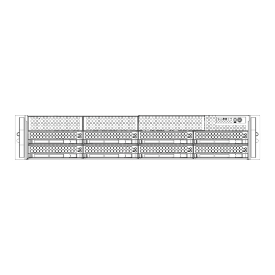
SUPERSERVER 6027R-73DARF User's Manual Figure 6-1. Front and Rear Chassis Views 3.5" Drive Bays (2) USB Ports (2) DVD-ROM Drive (Optional) Control Panel SAS/SATA Drives (8) System Reset Main Power Power Supplies 7 Low-profi le PCI Slots Rear I/O Ports (see Section 5-3) Control Panel The control panel (located on the front of the chassis) must be connected to the JF1 connector on the serverboard to provide you with system status indications. -
Page 81: Replacing System Fans
Installing a New Fan 1. Replace the failed fan with an identical 8-cm, 12-volt fan (available from Supermicro). 2. Position the new fan into the space vacated by the failed fan previously removed. A "click" can be heard when the fan is fully installed in place and the power connections are made. -
Page 82: Drive Bay Installation/Removal
Proceed to the "DVD-ROM Installation" section later in this chapter for instructions. Warning: Enterprise level hard disk drives are recommended for use in Supermicro chassis and servers. For information on recommended HDDs, visit the Supermicro Web site at http://www.supermicro.com/products/nfo/fi les/ storage/SAS-CompList.pdf... -
Page 83: Hard Drive Backplane
Chapter 6: Advanced Chassis Setup Figure 6-3. Removing a Drive Carrier Handle Release Button Figure 6-4. Mounting a Drive in a Carrier Caution: Regardless of how many hard drives are installed, all drive carriers must remain in the drive bays to maintain proper airfl ow. Use caution when working around the backplane. -
Page 84: Dvd-Rom Installation (Optional)
DVD-ROM Installation (Optional) The top cover of the chassis must be opened to gain full access to the DVD-ROM drive bay. The SuperServer 6028R-WTR(T) accomodates only slim type DVD-ROM drives. Side mounting brackets are typically needed to mount a slim DVD-ROM drive in the server. -
Page 85: Power Supply
Chapter 6: Advanced Chassis Setup Power Supply The SuperServer 6028R-WTR(T) has a 740 Watt redundant power supply consisting of two power modules. Each power supply module has an auto-switching capability, which enables it to automatically sense and operate at a 100V - 240V input voltage. - Page 86 SUPERSERVER 6027R-73DARF User's Manual Notes...
-
Page 87: Chapter 7 Bios
Chapter 7: BIOS Chapter 7 BIOS Introduction This chapter describes the AMI BIOS Setup utility for the X10DRW-i(T) It also provides the instructions on how to navigate the AMI BIOS Setup utility screens. The AMI ROM BIOS is stored in a Flash EEPROM and can be easily updated. Starting BIOS Setup Utility To enter the AMI BIOS Setup utility screens, press the <Del>... -
Page 88: How To Change The Confi Guration Data
SUPERSERVER 6028R-WTR(T) USER'S MANUAL How To Change the Confi guration Data The confi guration data that determines the system parameters may be changed by entering the AMI BIOS Setup utility. This Setup utility can be accessed by pressing <Delete> at the appropriate time during system boot. -
Page 89: Advanced Setup Confi Gurations
Chapter 7: BIOS Memory Information Total Memory This displays the amount of memory that is available in the system. Advanced Setup Confi gurations Use the arrow keys to select Advanced and press <Enter> to access the following submenu items: Boot Feature Quiet Boot Use this feature to select the bootup screen display between POST messages or the OEM logo. - Page 90 SUPERSERVER 6028R-WTR(T) USER'S MANUAL Bootup Num-Lock Use this feature to set the Power-on state for the Numlock key. The options are Off and On. Wait For 'F1' If Error If this feature is set to Enabled, the system will wait until the 'F1' key is pressed when an error occurs.
- Page 91 Chapter 7: BIOS CPU Confi guration This submenu displays the information of the CPU as detected by the BIOS. It also allows the user to confi gure the CPU settings. Socket 1 CPU Information/Socket 2 CPU Information This submenu displays the following information regarding the CPU installed in Socket 1 or Socket 2.
- Page 92 SUPERSERVER 6028R-WTR(T) USER'S MANUAL RTID (Record Types IDs) This feature displays the total number of Record Type IDs for local and remote pools. The options are Optimal and Alternate. Hyper-threading Select Enabled to support Intel Hyper-threading Technology to enhance CPU performance.
- Page 93 Chapter 7: BIOS DCU Streamer Prefetcher (Available when supported by the CPU) Select Enabled to support Data Cache Unite (DCU) prefetch to speed up data accessing and processing in the DCU to enhance CPU performance. The options are Disabled and Enabled. DCU IP Prefetcher Select Enabled for DCU (Data Cache Unit) IP Prefetcher support, which will prefetch IP addresses to enhance network connectivity and system performance.
- Page 94 SUPERSERVER 6028R-WTR(T) USER'S MANUAL C1E Support (Available when Power Technology is set to Custom) Select Enabled to enable Enhanced C1 Power State to boost system performance. The options are Enabled and Disabled. CPU C3 Report (Available when Power Technology is set to Custom) Select Enabled to allow the BIOS to report the CPU C3 State (ACPI C2) to the operating system.
- Page 95 Chapter 7: BIOS Long Duration Maintained This item displays the period of time (in seconds) during which long duration power is maintained. The default setting is 0. Recommended Short Duration Power Limit This item displays the short duration power settings (in watts) recommended by the manufacturer.
- Page 96 SUPERSERVER 6028R-WTR(T) USER'S MANUAL ® Intel I/OAT Select Enabled to enable Intel I/OAT (I/O Acceleration Technology), which will significantly reduce CPU overhead by leveraging CPU architectural improvements and freeing the system resource up for other tasks. The options are Disabled and Enabled.
- Page 97 Chapter 7: BIOS QPI (Quick Path Interconnect) Link Speed Mode Use this feature to select data transfer speed for QPI Link connections. The options are Fast and Slow. QPI Link Frequency Select Use this feature to select the desired QPI frequency. The options are Auto, 6.4 GT/s, 7.2 GT/s, and 8.0 GT/s.
- Page 98 SUPERSERVER 6028R-WTR(T) USER'S MANUAL Channel Interleaving This feature selects from the different channel interleaving methods. The options are Auto, 1 Way, 2 Way, 3, Way, and 4 Way. Rank Interleaving This feature allows the user to select a rank memory interleaving method. The options are Auto, 1 Way, 2 Way, 4, Way, and 8 Way.
-
Page 99: South Bridge
Chapter 7: BIOS South Bridge This feature allows the user to confi gure the settings for the Intel PCH chip. PCH Information This feature displays the following PCH information. Name: This item displays the name of the PCH chip. Stepping: This item displays the PCH stepping. USB Devices: This item displays the USB devices detected by the BIOS. - Page 100 SUPERSERVER 6028R-WTR(T) USER'S MANUAL SATA Confi guration When this submenu is selected, the AMI BIOS automatically detects the presence of IDE or SATA devices and displays the following items. SATA Port0~SATA Port5: The AMI BIOS displays the status of each SATA port as detected by the BIOS.
- Page 101 Chapter 7: BIOS SATA RAID Option ROM/UEFI Driver Select Enabled to boot the system from a SATA RAID device or a UEFI (Unifi ed Extensible Firmware Interface) device. The options are Enabled or Disabled. Port 0~5 Hot Plug Select Enabled to enable hot-plug support for a port specifi ed by the user. The options are Enabled and Disabled.
- Page 102 SUPERSERVER 6028R-WTR(T) USER'S MANUAL ASPM Support This feature allows the user to set the Active State Power Management (ASPM) level for a PCI-E device. Select Auto to allow the system BIOS to automatically set the ASPM level for the system. Select Disabled to disable ASPM support. The options are Disabled and Auto.
- Page 103 Chapter 7: BIOS Super IO Confi guration Super IO Chip Displays the Super IO chip type. COM 1 Confi guration Serial Port Select Enabled to enable a serial port specifi ed by the user. The options are Enabled and Disabled. Device Settings This item displays the settings of Serial Port 1.
-
Page 104: Serial Port Console Redirection
SUPERSERVER 6028R-WTR(T) USER'S MANUAL SOL (Serial_Over_LAN) Device Mode Use this feature to select the desired mode for the SOL port. The options are Normal and High Speed. Serial Port 2 Attribute Use this feature to select the attribute for serial port 2. The options are SOL (Serial_On_LAN), and COM. - Page 105 Chapter 7: BIOS Data Bits Use this feature to set the data transmission size for Console Redirection. The options are 7 and 8 (Bits). Parity A parity bit can be sent along with regular data bits to detect data transmission errors.
- Page 106 SUPERSERVER 6028R-WTR(T) USER'S MANUAL Putty Keypad Use this feature to select function key and keypad setting on Putty. The options are VT100, LINUX, XTERMR6, SCO, ESCN, and VT400. Redirection After BIOS POST If Always Enabled is selected, Legacy Console Redirection will be enabled for Legacy OS after BIOS POST (Power-On Self Test) is completed.
-
Page 107: Acpi Settings
Chapter 7: BIOS Flow Control This feature allows the user to set the fl ow control for Console Redirection to prevent data loss caused by buffer overfl ow. Send a "Stop" signal to stop sending data when the receiving buffer is full. Send a "Start" signal to start sending data when the receiving buffer is empty. - Page 108 SUPERSERVER 6028R-WTR(T) USER'S MANUAL High Precision Event Timer Select Enabled to activate the High Precision Event Timer (HPET) that produces periodic interrupts at a much higher frequency than a Real-time Clock (RTC) does in synchronizing multimedia streams, providing smooth playback, reducing the dependency on other timestamp calculation devices, such as an x86 RDTSC Instruction embedded in the CPU.
-
Page 109: Event Logs
Chapter 7: BIOS Intel TXT(LT-SX) Confi guration This feature indicates if the following hardware components support the Intel TXT (Trusted Execution Technology), which helps protect against software-based attacks and ensures protection, confi dentiality and integrity of data stored or created on the system. - Page 110 SUPERSERVER 6028R-WTR(T) USER'S MANUAL Runtime Error Logging Support Change this item to enable or disable runtime error logging. The options are Enabled and Disabled. Memory Correction Error Threshold Change this item to defi ne the system's memory correction error threshold. Directly enter a numeric value.
-
Page 111: Ipmi
Chapter 7: BIOS IPMI Use this menu to confi gure Intelligent Platform Management Interface (IPMI) settings. System Event Log Enabling/Disabling Options SEL Components Select Enabled for all system event logging at bootup. The options are Enabled and Disabled. Erasing Settings Erase SEL Select 'Yes, On next reset' to erase all system event logs upon next system reboot. - Page 112 SUPERSERVER 6028R-WTR(T) USER'S MANUAL When SEL is Full This feature allows the user to decide what the BIOS should do when the system event log is full. Select Erase Immediately to erase all events in the log when the system event log is full. The options are Do Nothing and Erase Immediately.
-
Page 113: Boot
Chapter 7: BIOS Boot This menu allows the user to confi gure the following boot settings for the system. Set Boot Priorities 1st Boot Device/2nd Boot Device/3rd Boot Device/4th Boot Device/5th Boot Device/6th Boot Device Use this feature to specify the sequence of boot priority for a device specifi ed by the user. -
Page 114: Security
SUPERSERVER 6028R-WTR(T) USER'S MANUAL USB Hard Disk Drive BBS Priorities This submenu allows the user to specify the boot priority sequence of a USB hard drive. 1st Device Network Device BBS Priorities This submenu allows the user to specify the boot priority sequence of a network device. -
Page 115: Save & Exit
Chapter 7: BIOS Password Check This item allows you to decide when the system should check for a password after it has been entered. Select Setup for the system to prompt for a password before the user enters the BIOS Setup utility. Select Always for the system to prompt for a password upon each system boot and before the user enters the Setup utility. - Page 116 SUPERSERVER 6028R-WTR(T) USER'S MANUAL Save Changes and Reset When you have completed the system confi guration changes, select this option to save the changes and reboot the computer so that the new system confi guration settings can take effect. Select Save Changes and Exit, and press <Enter>. When...
- Page 117 Chapter 7: BIOS Boot Override This feature allows the user to override the Boot Option Priorities setting in the Boot menu, and instead immediately boot the system with one of the listed devices. This is a one-time override. 7-31...
- Page 118 SUPERSERVER 6028R-WTR(T) USER'S MANUAL Notes 7-32...
-
Page 119: Appendix A Bios Error Beep Codes
Appendix A: BIOS POST Error Codes Appendix A BIOS Error Beep Codes During the POST (Power-On Self-Test) routines, which are performed at each system boot, errors may occur. Non-fatal errors are those which, in most cases, allow the system to continue to boot. - Page 120 SUPERSERVER 6028R-WTR(T) USER'S MANUAL Notes...
-
Page 121: Appendix B System Specifi Cations
Appendix B: System Specifi cations Appendix B System Specifi cations Processors Single or dual Intel® Xeon E5-2600v3 Series processors. Note: If using a single processor only, then slots SXB1B and SXB2 (lower left) will NOT be functional Note: Please refer to our web site for a complete listing of supported processors. Chipset Intel PCH-C612 chipset BIOS... - Page 122 UPER ERVER 6027R-73DARF User's Manual Weight 57 lbs. (25.9 kg.) System Cooling Three 8-cm system cooling fans Note: The system cooling fans are redundant, hot-plug. System Input Requirements AC Input Voltage: 100 - 240V AC auto-range Rated Input Current: 9 - 3.5A max Rated Input Frequency: 50 to 60 Hz Power Supply Output Rated Output Power: 740 Watt (Part# PWS-741P-1R)
- Page 123 Appendix B: System Specifi cations Notes...
- Page 124 ERVER 6027R-73DARF User's Manual (continued from front) The products sold by Supermicro are not intended for and will not be used in life support systems, medical equipment, nuclear facilities or systems, aircraft, aircraft devices, aircraft/emergency com- munication devices or other critical systems whose failure to perform be reasonably expected to result in signifi...
Need help?
Do you have a question about the 6028R-WTR and is the answer not in the manual?
Questions and answers