Table of Contents
Advertisement
Quick Links
Advertisement
Table of Contents

Related Manuals for Supermicro SuperStorage 6029P-E1CR16T


Summary of Contents for Supermicro SuperStorage 6029P-E1CR16T
- Page 1 SuperStorage 6029P-E1CR16T USER’S MANUAL Revision 1.0d...
- Page 2 State of California, USA. The State of California, County of Santa Clara shall be the exclusive venue for the resolution of any such disputes. Supermicro's total liability for all claims will not exceed the price paid for the hardware product.
- Page 3 About this Manual This manual is written for professional system integrators and PC technicians. It provides information for the installation and use of the SuperStorage 6029P-E1CR16T. Installation and maintenance should be performed by experienced technicians only. Please refer to the 6029P-E1CR16T specifications page on our website for updates on supported memory, processors and operating systems (http://www.supermicro.com).
-
Page 4: Table Of Contents
Preface Contents Chapter 1 Introduction 1.1 Overview ..........................8 1.2 Unpacking the System ......................8 1.3 System Features ........................9 1.4 Server Chassis Features ....................10 Control Panel ........................10 Front Features ........................11 Rear Features ........................12 Quick Reference Table ......................14 Chapter 2 Server Installation 2.1 Overview ..........................17 2.2 Preparing for Setup ......................17 Choosing a Setup Location ....................17 Rack Precautions ......................17... - Page 5 SuperStorage 6029P-E1CR16T User's Manual 3.3 Motherboard Components ....................27 Processor and Heatsink Installation ..................27 The Xeon Scalable Processor ..................27 Overview of the Processor Socket Assembly ..............28 Overview of the Processor Heatsink Module (PHM) .............29 Assembling the Processor Package ................30 Assembling the Processor Heatsink Module (PHM) .............31 Removing the Processor Heatsink Module from the Motherboard .......32...
- Page 6 Preface Ethernet Ports ........................58 Rear I/O Ports ........................60 4.4 Jumpers ..........................61 Explanation of Jumpers ....................61 4.5 LED Indicators ........................64 Chapter 5 Software 5.1 Microsoft Windows OS Installation ..................65 5.2 Driver Installation ........................67 5.3 SuperDoctor 5 ........................68 ® 5.4 IPMI ............................68 Chapter 6 UEFI BIOS 6.1 Introduction .........................69 Starting the Setup Utility ....................69...
- Page 7 SuperStorage 6029P-E1CR16T User's Manual Contacting Supermicro Headquarters Address: Super Micro Computer, Inc. 980 Rock Ave. San Jose, CA 95131 U.S.A. Tel: +1 (408) 503-8000 Fax: +1 (408) 503-8008 Email: marketing@supermicro.com (General Information) support@supermicro.com (Technical Support) Website: www.supermicro.com Europe Address: Super Micro Computer B.V.
-
Page 8: Overview
SuperStorage 6029P-E1CR16T User's Manual Chapter 1 Introduction 1.1 Overview This chapter provides a brief outline of the functions and features of the 6029P-E1CR16T. The 6029P-E1CR16T is based on the X11DPH-T motherboard and the SC829HE1C4-R1K62LPB chassis. In addition to the motherboard and chassis, several important parts that are included with the system are listed below. -
Page 9: System Features
Chapter 1: Introduction 1.3 System Features The following table provides you with an overview of the main features of the 6029P-E1CR16T. Please refer to Appendix C for additional specifications. System Features Motherboard X11DPH-T Chassis SC829HE1C4-R1K62LPB Dual Intel® Xeon® 81xx/61xx/51xx/41xx/31xx and 82xx/62xx/52xx/42xx/32xx series processors * Socket Type Socket P Memory... -
Page 10: Server Chassis Features
SuperStorage 6029P-E1CR16T User's Manual 1.4 Server Chassis Features Control Panel The switches and LEDs located on the control panel are described below. See Chapter 4 for details on the control panel connections. Figure 1-1. Control Panel View Control Panel Features... -
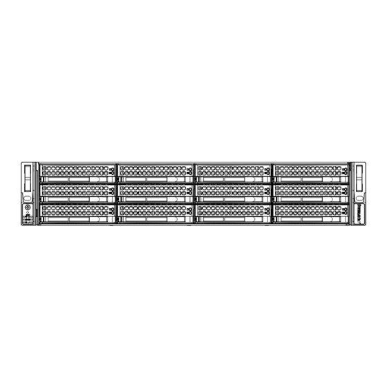
Page 11: Front Features
Chapter 1: Introduction Information LED Status Description Continuously on and red An overheat condition has occurred. (This may be caused by cable congestion.) Blinking red (1 Hz) Fan failure: check for an inoperative fan. Blinking red (0.25 Hz) Power failure: check for an inoperative power supply. UID has been activated locally to locate the server in a rack environment. -
Page 12: Rear Features
SuperStorage 6029P-E1CR16T User's Manual Rear Features The illustration below shows the features included on the rear of the chassis. Figure 1-3. Chassis Rear View Rear Chassis Features Item Feature Description Power Supply Module 1600W power supply (redundant, with two power modules) I/O Ports I/O ports (see Section 4.3 for details) - Page 13 Chapter 1: Introduction USB2/3 (3.0) SLOT7 JSDCARD1 SLOT6 IPMI LAN LEDM1 SLOT3 SLOT5 FAN6 FAN5 USB0/1 (3.0) JNCSI SLOT1 SLOT4 LAN2 SLOT2 COM1 LAN1 JUIDB1 JPG1 USB 2/3(3.0) JPG1 JPL1 COM1 FAN5 JTPM1 JSDCARD1 AST2500 LAN2 LAN1 IPMI_LAN CTRL FAN6 USB 0/1(3.0) JPME2 JPME2...
-
Page 14: Quick Reference Table
SuperStorage 6029P-E1CR16T User's Manual Quick Reference Table Jumper Description Default Setting JBT1 CMOS Clear Open (Normal) JPG1 VGA Enable Pins 1-2 (Enabled) JPL1 LAN1/LAN2 Enable Pins 1-2 (Enabled) JPME1 ME Recovery Pins 1-2 (Normal) JPME2 ME Manufacturing Mode Pins 1-2 (Normal) - Page 15 Description (CPU2) SLOT2, SLOT4, PCI-Express 3.0 x16 slots supported by CPU2 SLOT5 S-SATA0, S-SATA1 Powered SATA 3.0 ports with support of Supermicro SuperDOM (Disk-On-Module) T-SGPIO1 Serial Link General Purpose I/O (SGPIO) port USB0/1, USB2/3 Universal Serial Bus (USB) 3.0 ports USB4/5 Internal USB 3.0 header for front access...
- Page 16 SuperStorage 6029P-E1CR16T User's Manual #F-0 VCCP1 12v VCCP0 12v #M-0 #E-0 #L-0 VR13 VR13 #D-1 #K-1 5+1 PHASE 6+1 PHASE #D-0 #K-0 up to 255W #C-0 10.4/11.2G #J-0 #B-0 #H-0 VCCP1 VCCP0 #A-1 #G-1 #A-0 SNB CORE #G-0 SNB CORE...
-
Page 17: Chapter 2 Server Installation
Chapter 2: Server Installation Chapter 2 Server Installation 2.1 Overview This chapter provides advice and instructions for mounting your system in a server rack. If your system is not already fully integrated with processors, system memory etc., refer to Chapter 4 for details on installing those specific components. Caution: Electrostatic Discharge (ESD) can damage electronic components. -
Page 18: Server Precautions
SuperStorage 6029P-E1CR16T User's Manual • Always make sure the rack is stable before extending a server or other component from the rack. • You should extend only one server or component at a time - extending two or more simul- taneously may cause the rack to become unstable. -
Page 19: Circuit Overloading
Chapter 2: Server Installation Circuit Overloading Consideration should be given to the connection of the equipment to the power supply circuitry and the effect that any possible overloading of circuits might have on overcurrent protection and power supply wiring. Appropriate consideration of equipment nameplate ratings should be used when addressing this concern. -
Page 20: Installing The Rails
SuperStorage 6029P-E1CR16T User's Manual 2.3 Installing the Rails There are a variety of rack units on the market, which may require a slightly different assembly procedure. The following is a basic guideline for installing the system into a rack with the rack mounting hardware provided. -
Page 21: Releasing The Inner Rail
Chapter 2: Server Installation Releasing the Inner Rail Each inner rail has a locking latch. This latch prevents the server from coming completely out of the rack when when the chassis is pulled out for servicing. To mount the rail onto the chassis, first release the inner rail from the outer rails. Releasing Inner Rail from the Outer Rails 1. -
Page 22: Installing The Inner Rails On The Chassis
SuperStorage 6029P-E1CR16T User's Manual Installing the Inner Rails on the Chassis Installing the Inner Rails 1. Identify the left and right inner rails. They are labeled. 2. Place the inner rail firmly against the side of the chassis, aligning the hooks on the side of the chassis with the holes in the inner rail. -
Page 23: Installing The Outer Rails Onto The Rack
Chapter 2: Server Installation Installing the Outer Rails onto the Rack Installing the Outer Rails 1. Press upward on the locking tab at the rear end of the middle rail. 2. Push the middle rail back into the outer rail. 3. -
Page 24: Sliding The Chassis Onto The Rack Rails
SuperStorage 6029P-E1CR16T User's Manual Sliding the Chassis onto the Rack Rails Warning: Mounting the system into the rack requires at least two people to support the chassis during installation. Please follow safety recommendations printed on the rails. Installing the Chassis into a Rack 1. -
Page 25: Chapter 3 Maintenance And Component Installation
SuperStorage 6029P-E1CR16T User's Manual Chapter 3 Maintenance and Component Installation This chapter provides instructions on installing and replacing main system components. To prevent compatibility issues, only use components that match the specifications and/or part numbers given. Installation or replacement of most components require that power first be removed from the system. - Page 26 Chapter 3: Maintenance and Component Installation 6. To remove the system from the rack completely, press the locking tabs in the chassis rails (push the right-side tab down and the left-side tab up) to continue to pull the system out past the locked position. Warning: Except for short periods of time, do not operate the server without the cover in place.
-
Page 27: Motherboard Components
CPU socket cap is in place and none of the socket pins are bent; otherwise, contact your retailer immediately. • Refer to the Supermicro website for updates on CPU support. The Xeon Scalable Processor The Intel Xeon Dual Intel® Xeon® 81xx/61xx/51xx/41xx/31xx and 82xx/62xx/52xx/42xx/32xx series processors comes in two models: Fabric (F Model) and Non-Fabric (Non-F Model). -
Page 28: Overview Of The Processor Socket Assembly
Chapter 3: Maintenance and Component Installation Overview of the Processor Socket Assembly The processor socket assembly contains 1) the Intel processor, 2) the narrow processor clip, 3) the dust cover, and 4) the CPU socket. 1. Processor 2. Narrow processor clip (the plastic processor package carrier used for the CPU) 3. -
Page 29: Overview Of The Processor Heatsink Module (Phm)
SuperStorage 6029P-E1CR16T User's Manual Overview of the Processor Heatsink Module (PHM) The Processor Heatsink Module (PHM) contains 1) a heatsink, 2) a narrow processor clip, and 3) the processor. 1. Heatsink 2. Narrow processor clip 3. SKX(-F) Processor (Bottom View for a non-F Model) -
Page 30: Assembling The Processor Package
Chapter 3: Maintenance and Component Installation Assembling the Processor Package Attach the processor to the narrow processor clip to create the processor package. Caution: Exercise extreme caution when handling the CPU. Do not touch the underside of the CPU to avoid damaging it. Be sure to wear ESD gloves when handling components. 1. -
Page 31: Assembling The Processor Heatsink Module (Phm)
SuperStorage 6029P-E1CR16T User's Manual Assembling the Processor Heatsink Module (PHM) After creating the processor package assembly, mount it onto the heatsink to create the processor heatsink module (PHM). 1. Locate "1" on the heatsink label and the corner next to it. With your index finger pressing against the screw at this corner, carefully turn the heatsink upside down with the thermal grease side facing up. -
Page 32: Removing The Processor Heatsink Module From The Motherboard
Chapter 3: Maintenance and Component Installation Removing the Processor Heatsink Module from the Motherboard Before removing the processor heatsink module (PHM), power down as described in Section 3.1. 1. Using a T30 Torx-bit screwdriver, turn the screws on the PHM counterclockwise to loosen them from the socket, starting with screw marked #4, in the sequence of 4, 3, 2, 2. -
Page 33: Memory Installation
• Put the memory modules into the antistatic bags when not in use. • Check the Supermicro website for recommended memory modules Introduction to Intel® Optane DC Persistent Memory Intel® 82xx/62xx/52xx/4215 supports new DCPMM (Optane™ DC Persistent Memory Modules) technology. DCPMM offers data persistence with higher capacity at lower latencies than the existing memory modules and provides hyper-speed storage capability for high performance computing platforms with flexible configuration options. -
Page 34: Memory Installation Sequence
Chapter 3: Maintenance and Component Installation DDR4 Memory Support for 81xx/61xx/51xx/41xx/31xx Processors Speed (MT/s) Ranks DIMM Capacity (GB) One Slot Two Slots per Channel per Channel DIMM Type One DIMM One DIMM Two DIMMs DRAM Density Data per Channel per Channel per Channel Width 4 Gb... -
Page 35: General Memory Population Requirements
SuperStorage 6029P-E1CR16T User's Manual General Memory Population Requirements 1. Be sure to use the memory modules of the same type and speed on the motherboard. Mixing of memory modules of different types and speeds is not allowed. 2. Using unbalanced memory topology such as populating two DIMMs in one channel while populating one DIMM in another channel on the same motherboard will result in reduced memory performance. - Page 36 Chapter 3: Maintenance and Component Installation Note: Unbalanced memory configuration decreases memory performance and is not recommended for Supermicro motherboards. Memory Population Table for the X11DP Motherboard w/16 DIMM Slots Onboard CPUs/DIMMs Memory Population Sequence 1 CPU & 1 DIMM CPU1: P1-DIMMA1 1 CPU &...
- Page 37 SuperStorage 6029P-E1CR16T User's Manual Symmetric Population within 1 CPU Socket Channel Modes DIMMF1 DIMME1 DIMMD1 DIMMD2 DIMMA2 DIMMA1 DIMMB1 DIMMC1 Config. DRAM1 DRAM1 DRAM1 DCPMM DCPMM DRAM1 DRAM1 DRAM1 2-1-1 DRAM2 DRAM2 DRAM2 DCPMM DCPMM DRAM2 DRAM2 DRAM2 2-1-1 AD + MM DRAM3...
-
Page 38: Dimm Installation
Chapter 3: Maintenance and Component Installation DIMM Installation USB 2/3(3.0) JPG1 COM1 FAN5 JSDCARD1 AST2500 1. Follow the instructions given in the LAN2 LAN1 IPMI_LAN CTRL FAN6 USB 0/1(3.0) JPME2 CPU2 memory population guidelines listed in the previous sections to install memory modules on your motherboard. -
Page 39: Pci Expansion Card Installation
SuperStorage 6029P-E1CR16T User's Manual PCI Expansion Card Installation The 6029P-E1CR16T can accommodate up to seven low-profile add-on cards in the PCI expansion slots on the serverboard. Installing Add-on Card 1. Begin by removing the shield for the PCI slot you wish to populate. Make sure that the card you are installing is supported by the slot (see table below). -
Page 40: Chassis Components
Chapter 3: Maintenance and Component Installation 3.4 Chassis Components Removing and Installing Hard Drives The SC829U chassis accepts twelve hot-swappable 3.5" hard drives. The hard drives are mounted in drive carriers to simplify their installation and removal from the chassis. System power may remain on when removing carriers with drives installed. - Page 41 Figure 3-5. Removing a Dummy Drive from a Carrier Note: Enterprise level hard disk drives are recommended for use in Supermicro chassis and servers. For information on recommended HDDs, visit the Supermicro website at http://www.
- Page 42 Chapter 3: Maintenance and Component Installation Hard Drive Drive Carrier Figure 3-6. Installing a Hard Drive Figure 3-7. Installing a Carrier into its Bay...
-
Page 43: Internal 3.5" Hard Drives
SuperStorage 6029P-E1CR16T User's Manual Internal 3.5" Hard Drives The SC829U chassis supports four internal hot-swap 3.5" hard drives which are mounted in individual hard drive trays contained in an internal chassis tray. After the chassis tray has been installed into the chassis, the power can stay on when removing or installing the hard drives from their individual trays. - Page 44 Chapter 3: Maintenance and Component Installation 5. Lift the individual trays up and out of the chassis tray. Figure 6-12. Removing a Hard Drive Carrier from the Hard Drive Tray 6. Place a hard drive into each of the individual trays and secure it with four screws. 7.
- Page 45 SuperStorage 6029P-E1CR16T User's Manual 8. Secure the individual trays into the chassis tray with four screws. Figure 6-14. Installing Hard Drives and Carriers into the Hard Drive Tray 9. Place the loaded chassis tray into the chassis. Figure 6-15. Installing the Hard Drive Tray into the Chassis 10.
- Page 46 Chapter 3: Maintenance and Component Installation After installing the chassis tray and individual trays, the internal hot-swappable hard drives may be removed without powering down the system. Removing Internal Hard Drives from the Chassis Tray 1. Confirm that that chassis tray and individual trays have been installed as directed in the previous section.
-
Page 47: Adding Pci Expansion Cards
(CPU2) Full Height, full length x8 (CPU2) Full height = 4.2", Low profile = 2.5", Full length = 10.5", Half length = 6.6" * This slot supports only Supermicro SAS Cards listed below. Supermicro SAS Cards Part Number Description... - Page 48 Chapter 3: Maintenance and Component Installation Ultra Riser Bracket WIO Riser Bracket Figure 3-9. Expansion and Riser Cards—Rear View Installing PCI Expansion Cards 1. Power down the system and remove the top chassis cover. 2. Remove the Ultra riser bracket or WIO riser bracket by flipping up its riser cage release tab as pictured in Figure 3-10.
-
Page 49: System Fans
SuperStorage 6029P-E1CR16T User's Manual System Fans The chassis contains four 8-cm high-performance fans. Replacing a System Fan Fan speed is controlled by system temperature via IPMI. If a fan fails, the remaining fan will ramp up to full speed and the overheat/fan fail LED on the control panel will turn on. Replace any failed fan at your earliest convenience with the same type and model (the system can continue to run with a failed fan). -
Page 50: Power Supply
The Power Fail LED will illuminate and remain on until the failed unit has been replaced. Replacement units can be ordered directly from Supermicro. The power supply units have a hot-plug capability, meaning you can replace the failed unit without powering down the system. -
Page 51: Chapter 4 Motherboard Connections
Chapter 4: Motherboard Connections Chapter 4 Motherboard Connections This section describes the connections on the motherboard and provides pinout definitions. Note that depending on how the system is configured, not all connections are required. The LEDs on the motherboard are also described here. A serverboard layout indicating component locations may be found in Chapter 1. -
Page 52: Headers And Connectors
SuperStorage 6029P-E1CR16T User's Manual Processor Power Connector JPWR1, JPWR2 and JPWR4 are the 8-pin 12V DC power inputs for the CPU or alternative single power source for a special enclosure when the 24-pin ATX power is not in use. 12V 8-pin Power... - Page 53 4-7 ports are supported by the Intel PCH, while S-SATA0/1 are supported by Intel SCU. S-SATA1/2 can be used with Supermicro SuperDOMs, which are yellow SATA DOM connectors with built-in power pins that do not require external power cables. Supermicro SuperDOMs are backward-compatible with regular SATA HDDs or SATA DOMs that need external power cables.
- Page 54 SuperStorage 6029P-E1CR16T User's Manual TPM Header The JTPM1 header is used to connect a Trusted Platform Module (TPM)/Port 80, which is available from a third-party vendor. A TPM/Port 80 connector is a security device that supports encryption and authentication in hard drives. It allows the motherboard to deny access if the TPM associated with the hard drive is not installed in the system.
- Page 55 Chapter 4: Motherboard Connections Standby Power The Standby Power header is located at JSTBY1 on the motherboard. You must have a card with a Standby Power connector and a cable to use this feature. Standby Power Pin Definitions Pin# Definition +5V Standby Ground No Connection...
-
Page 56: Control Panel
SuperStorage 6029P-E1CR16T User's Manual Control Panel JF1 contains header pins for various control panel connections. See the figure below for the pin locations and definitions of the control panel buttons and LED indicators. All JF1 wires have been bundled into a single cable to simplify this connection. Make sure the red wire plugs into pin 1 as marked on the motherboard. - Page 57 Chapter 4: Motherboard Connections Power Fail LED The Power Fail LED connection is located on pins 5 and 6 of JF1. Power Fail LED Pin Definitions (JF1) Pin# Definition 3.3V PWR Supply Fail OH/Fan Fail/PWR Fail/UID LED Connect an LED cable to pins 7 and 8 of the Front Control Panel (JF1) to use UID/Overheat/ Fan Fail/Power Fail LED connections.
-
Page 58: Ports
SuperStorage 6029P-E1CR16T User's Manual Power LED The Power LED connection is located on pins 15 and 16 of JF1. Power LED Pin Definitions (JF1) Pins Definition 3.3V PWR LED NMI Button The non-maskable interrupt (NMI) button header is located on pins 19 and 20 of JF1. - Page 59 Chapter 4: Motherboard Connections Universal Serial Bus (USB) Ports Four USB 3.0 ports (USB 0/1, USB 2/3) are located on the I/O back panel. An internal USB header, located next to SATA 4~7, provides two USB 3.0 connections (USB2/3) for front access.
-
Page 60: Rear I/O Ports
Note: UID can also be triggered via IPMI on the motherboard. For more information on IPMI, please refer to the IPMI User's Guide posted on our website at http://www.supermicro.com. UID Switch... -
Page 61: Jumpers
Chapter 4: Motherboard Connections 4.4 Jumpers Explanation of Jumpers To modify the operation of the motherboard, jumpers are used to choose between optional settings. Jumpers create shorts between two pins to change the function associated with it. Pin 1 is identified with a square solder pad on the printed circuit board. See the motherboard layout page for jumper locations. - Page 62 SuperStorage 6029P-E1CR16T User's Manual VGA Enable/Disable JPG1 allows you to enable or disable the VGA port using the onboard graphics controller. The default setting is Enabled. VGA Enable/Disable Jumper Settings Jumper Setting Definition Pins 1-2 Enabled Pins 2-3 Disabled LAN1/2 Enable/Disable Change the setting of jumper JPL1 to enable or disable the LAN1 and LAN2 Ethernets ports, respectively.
- Page 63 Chapter 4: Motherboard Connections C Bus for VRM Jumpers JVRM1 and JVRM2 allow the VRM SMB clock and data to access the Baseboard Management Controller (BMC). JVRM1 (VRM SMB Clock to BMC) Jumper Settings Jumper Setting Definition Closed Enable (SMB Clock to BMC) Open Disable (SMB Clock to PCH) JVRM2 (VRM SMB Data to BMC)
-
Page 64: Led Indicators
SuperStorage 6029P-E1CR16T User's Manual 4.5 LED Indicators LAN1/2 LEDs The rear Ethernet ports have two LEDs. On each port, one LED indicates activity when flashing while the other LED may be green, amber or off to indicate the speed of the connection. -
Page 65: Chapter 5 Software
USB/SATA DVD drive, or a USB flash drive, or the IPMI KVM console. 2. Retrieve the proper RST/RSTe driver. Go to the Supermicro web page for your motherboard and click on "Download the Latest Drivers and Utilities", select the proper driver, and copy it to a USB flash drive. - Page 66 SuperStorage 6029P-E1CR16T User's Manual 4. During Windows Setup, continue to the dialog where you select the drives on which to install Windows. If the disk you want to use is not listed, click on “Load driver” link at the bottom left corner.
-
Page 67: Driver Installation
The Supermicro website contains drivers and utilities for your system at https://www. supermicro.com/wftp/driver. Some of these must be installed, such as the chipset driver. After accessing the website, go into the CDR_Images (in the parent directory of the above link) and locate the ISO file for your motherboard. Download this file to to a USB flash drive or a DVD. -
Page 68: Superdoctor ® 5
5.3 SuperDoctor ® The Supermicro SuperDoctor 5 is a program that functions in a command-line or web-based interface for Windows and Linux operating systems. The program monitors such system health information as CPU temperature, system voltages, system power consumption, fan speed, and provides alerts via email or Simple Network Management Protocol (SNMP). -
Page 69: Chapter 6 Uefi Bios
Chapter 6: BIOS Chapter 6 UEFI BIOS 6.1 Introduction This chapter describes the UEFI BIOS Setup utility for the X11DPH-T motherboard. The BIOS is stored on a chip and can be easily upgraded using a flash program. Note: Due to periodic changes to the BIOS, some settings may have been added or deleted and might not yet be recorded in this manual. -
Page 70: Main Setup
SuperStorage 6029P-E1CR16T User's Manual 6.2 Main Setup When you first enter the AMI BIOS setup utility, you will enter the Main setup screen. You can always return to the Main setup screen by selecting the Main tab on the top of the screen. The Main BIOS setup screen is shown below. - Page 71 Chapter 6: BIOS Memory Information Total Memory This item displays the total size of memory available in the system.
-
Page 72: Advanced Setup Configurations
SuperStorage 6029P-E1CR16T User's Manual 6.3 Advanced Setup Configurations Use the arrow keys to select the Advanced submenu and press <Enter> to access the submenu items. Warning: Take Caution when changing the Advanced settings. An incorrect value, an incorrect DRAM frequency, or an incorrect BIOS timing setting may cause the system to malfunction. - Page 73 Chapter 6: BIOS Wait For 'F1' If Error Select Enabled to force the system to wait until the 'F1' key is pressed if an error occurs. The options are Disabled and Enabled. INT19 Trap Response Interrupt 19 is the software interrupt that handles the boot disk function. When this item is set to Immediate, the ROM BIOS of the host adaptors will "capture"...
- Page 74 SuperStorage 6029P-E1CR16T User's Manual Power Button Function This feature controls how the system shuts down when the power button is pressed. Select 4 Seconds Override for the user to power off the system after pressing and holding the power button for 4 seconds or longer. Select Instant Off to instantly power off the system as soon as the user presses the power button.
- Page 75 Chapter 6: BIOS Execute Disable Bit (Available if supported by the OS & the CPU) Select Enable to enable Execute Disable Bit support which will allow the processor to designate areas in the system memory where an application code can execute and where it cannot, thus preventing a worm or a virus from flooding illegal codes to overwhelm the processor, damaging the system during a virus attack.
- Page 76 SuperStorage 6029P-E1CR16T User's Manual Extended APIC (Extended Advanced Programmable Interrupt Controller) Based on the Intel Hyper-Threading technology, each logical processor (thread) is assigned 256 APIC IDs (APIDs) in 8-bit bandwidth. When this feature is set to Enable, the APIC ID will be expanded from 8 bits to 16 bits to provide 512 APIDs to each thread to enhance CPU performance.
- Page 77 Chapter 6: BIOS CPU C State Control Autonomous Core C-State Select Enable to support Autonomous Core C-State control which will allow the processor core to control its C-State setting automatically and independently. The options are Enable and Disable. CPU C6 Report Select Enable to allow the BIOS to report the CPU C6 state (ACPI C3) to the operating system.
- Page 78 SuperStorage 6029P-E1CR16T User's Manual Chipset Configuration Warning: Setting the wrong values in the following sections may cause the system to malfunc- tion. North Bridge This feature allows the user to configure the settings for the Intel North Bridge.
- Page 79 Chapter 6: BIOS Select Enable to use the feature of "Secure Network Communications" (SNC), which supports full SNC (2-cluster) interleave and 1-way IMC interleave. Select Auto for 1-cluster or 2-cluster support depending on the satuts of IMC (Integrated Memory Controller) Interleaving.
- Page 80 SuperStorage 6029P-E1CR16T User's Manual Data Scrambling for NVDIMM Select Enable to enable data scrambling for onboard NVDIMM memory to enhance system performance and security. The options are Auto, Disable, and Enable. Data Scrambling for DDR4 Select Enable to enable data scrambling for DDR4 memory to enhance system performance and security.
- Page 81 Chapter 6: BIOS Memory RAS (Reliability_Availability_Serviceability) Configuration Use this submenu to configure the following Memory RAS settings. Static Virtual Lockstep Mode Select Enable to support Static Virtual Lockstep mode to enhance memory performance. The options are Enable and Disable. Mirror Mode Use this feature to configure the mirror mode settings for all 1LM/2LM memory modules installed in the system which will create a duplicate copy of data stored in the memory to...
- Page 82 SuperStorage 6029P-E1CR16T User's Manual Patrol Scrub Patrol Scrubbing is a process that allows the CPU to correct correctable memory errors detected in a memory module and send the corrections to the requestor (the original source). When this item is set to Enable, the IO hub will read and write back one cache line every 16K cycles if there is no delay caused by internal processing.
- Page 83 Chapter 6: BIOS CPU1 PCI-E Br0D00F0 - Port 0/DMI (Available for CPU 1 Configuration only) Link Speed This feature configures the link speed of a PCI-E port specified by the user. The options are Auto, Gen 1 (Generation 1) (2.5 GT/s), Gen 2 (Generation 2) (5 GT/s), and Gen 3 (Generation 3) (8 GT/s) The following information will be displayed as well: •...
- Page 84 SuperStorage 6029P-E1CR16T User's Manual Intel VT for Directed I/O (VT-d) Intel® VT for Directed I/O (VT-d) Select Enable to use Intel Virtualization Technology support for Direct I/O VT-d by reporting the I/O device assignments to the VMM (Virtual Machine Monitor) through the DMAR ACPI tables.
- Page 85 Chapter 6: BIOS IIO-PCIE Express Global Options PCI-E Completion Timeout Disable Select Yes to disable the PCI-E Completion Time-out settings. The options are Yes, No, and Per-Port. South Bridge The following South Bridge information will display: • USB Module Version •...
- Page 86 SuperStorage 6029P-E1CR16T User's Manual PCH SATA Configuration When this submenu is selected, the AMI BIOS automatically detects the presence of the SATA devices that are supported by the Intel PCH chip and displays the following items: SATA Controller This item enables or disables the onboard SATA controller supported by the Intel PCH chip.
- Page 87 Chapter 6: BIOS SATA Device Type Use this item to specify if the device installed on the SATA port selected by the user should be connected to a Solid State drive or a Hard Disk Drive. The options are Hard Disk Drive and Solid State Drive.
- Page 88 SuperStorage 6029P-E1CR16T User's Manual Spin Up Device On an edge detect from 0 to 1, set this item to allow the sSATA device installed on the sSATA port specified by the user to start a COMRESET initialization. The options are Enable and Disable.
- Page 89 Chapter 6: BIOS MMCFG Base This feature determines the lowest MMCFG (Memory-Mapped Configuration) base assigned to PCI devices. The options are 1G, 1.5G, 1.75G. 2G, 2.25G, and 3G. NVMe Firmware Source This feature determines which type of the NVMe firmware should be used in your system. The options are Vendor Defined Firmware and AMI Native Support.
- Page 90 SuperStorage 6029P-E1CR16T User's Manual Network Stack Configuration Network Stack Select Enabled to enable PXE (Preboot Execution Environment) or UEFI (Unified Extensible Firmware Interface) for network stack support. The options are Enabled and Disabled. *If "Network Stack" is set to Enabled, the following items will display: Ipv4 PXE Support Select Enabled to enable Ipv4 PXE boot support.
- Page 91 Chapter 6: BIOS Device Settings This feature displays the base I/O port address and the Interrupt Request address of a serial port specified by the user. Note: This item is hidden when Serial Port 1 is set to Disabled. Change Settings This feature specifies the base I/O port address and the Interrupt Request address of Serial Port 1.
- Page 92 SuperStorage 6029P-E1CR16T User's Manual Console Redirection Settings (when COM1 Console Redirection is Enabled) Terminal Type Use this feature to select the target terminal emulation type for Console Redirection. Select VT100 to use the ASCII Character set. Select VT100+ to add color and function key support.
- Page 93 Chapter 6: BIOS Recorder Mode Select Enabled to capture the data displayed on a terminal and send it as text messages to a remote server. The options are Disabled and Enabled. Resolution 100x31 Select Enabled for extended-terminal resolution support. The options are Disabled and Enabled.
- Page 94 SuperStorage 6029P-E1CR16T User's Manual Bits Per second Use this feature to set the transmission speed for a serial port used in Console Redirection. Make sure that the same speed is used in the host computer and the client computer. A lower transmission speed may be required for long and busy lines.
- Page 95 Chapter 6: BIOS Putty KeyPad This feature selects Function Keys and KeyPad settings for Putty, which is a terminal emulator designed for the Windows OS. The options are VT100, LINUX, XTERMR6, SCO, ESCN, and VT400. Redirection After BIOS Post Use this feature to enable or disable legacy Console Redirection after BIOS POST (Power-On Self-Test).
- Page 96 SuperStorage 6029P-E1CR16T User's Manual Bits Per Second This feature sets the transmission speed for a serial port used in Console Redirection. Make sure that the same speed is used in both host computer and the client computer. A lower transmission speed may be required for long and busy lines. The options are 9600, 19200, 57600, and 115200 (bits per second).
- Page 97 Chapter 6: BIOS Trusted Computing (Available when a TPM device is installed and detected by the BIOS) When a TPM (Trusted-Platform Module) device is detected in your machine, the following information will be displayed. • TPM2.0 Device Found • Vendor •...
- Page 98 SuperStorage 6029P-E1CR16T User's Manual Platform Hierarchy (for TPM Version 2.0 and above) Select Enabled for TPM Platform Hierarchy support which will allow the manufacturer to utilize the cryptographic algorithm to define a constant key or a fixed set of keys to be used for initial system boot.
- Page 99 Chapter 6: BIOS iSCSi Configuration iSCSI Initiator Name This feature allows the user to enter the unique name of the iSCSI Initiator in IQN format. Once the name of the iSCSI Initiator is entered into the system, configure the proper settings for the following items.
-
Page 100: Event Logs
SuperStorage 6029P-E1CR16T User's Manual 6.4 Event Logs Use this feature to configure Event Log settings. Change SMBIOS Event Log Settings Enabling/Disabling Options SMBIOS Event Log Select Enabled to enable SMBIOS (System Management BIOS) Event Logging during system boot. The options are Enabled and Disabled. - Page 101 Chapter 6: BIOS MECI (Multiple Event Count Increment) Enter the increment value for the multiple event counter. Enter a number between 1 to 255. The default setting is 1. METW (Multiple Event Count Time Window) Use this feature to determine how long (in minutes) the multiple event counter should wait before generating a new event log.
-
Page 102: Ipmi
SuperStorage 6029P-E1CR16T User's Manual 6.5 IPMI Use this feature to configure Intelligent Platform Management Interface (IPMI) settings. When you select this submenu and press the <Enter> key, the following information will display: • BMC Firmware Revision: This feature indicates the IPMI firmware revision used in your system. - Page 103 Chapter 6: BIOS When SEL is Full This feature allows the user to determine what the BIOS should do when the system event log is full. Select Erase Immediately to erase all events in the log when the system event log is full.
- Page 104 SuperStorage 6029P-E1CR16T User's Manual The following features will be displayed: • Current Configuration Address Source • Station IPV6 Address • Prefix Length • IPV6 Router1 IP Address • IPV6 Address Status • IPV6 DHCP Algorithm...
-
Page 105: Security Settings
Chapter 6: BIOS 6.6 Security Settings This menu allows the user to configure the following security settings for the system. Administrator Password Use this feature to set the administrator password which is required to enter the BIOS setup utility. The length of the password should be from 3 characters to 20 characters long. User Password Use this feature to set the user password which is required to enter the BIOS setup utility. - Page 106 SuperStorage 6029P-E1CR16T User's Manual Secure Boot If this feature is set to Enabled, Secure Boot will be activated when a Platform Key (PK) is entered. A Platform Key is a security key used to manage the security settings of the platform firmware used in your system.
- Page 107 Chapter 6: BIOS Key Exchange Keys This feature allows the user to enter and configure a set of values to be used as a Key- Exchange-Keys for the system. This set of values also indicate the size, the keys numbers, and the key source of the Key-Exchange-Keys.
-
Page 108: Boot Settings
SuperStorage 6029P-E1CR16T User's Manual 6.7 Boot Settings Use this feature to configure Boot Settings: Boot Mode Select Use this feature to select the type of devices to be used for system boot. The options are Legacy, UEFI (Unified Extensible Firmware Interface), and Dual. - Page 109 Chapter 6: BIOS Add New Boot Option This feature allows the user to add a new boot option to the boot priority features for your system. Add Boot Option Use this feature to specify the name for the new boot option. Path for Boot Option Use this feature to enter the path for the new boot option in the format fsx:\path\filename.efi.
- Page 110 SuperStorage 6029P-E1CR16T User's Manual Delete Driver Option Use this item to select a boot driver to delete from the boot priority list. Delete Drive Option Select the target boot driver to delete from the boot priority list. Hard Disk Drive BBS Priorities •...
-
Page 111: Save & Exit
Chapter 6: BIOS 6.8 Save & Exit Select the Save & Exit tab from the BIOS setup screen to configure the settings below. Save Options Discard Changes and Exit Select this option to quit the BIOS setup without making any permanent changes to the system configuration and reboot the computer. - Page 112 SuperStorage 6029P-E1CR16T User's Manual Default Options Restore Optimized Defaults To set this feature, select Restore Defaults from the Exit menu and press <Enter> to load manufacturer default settings which are intended for maximum system performance but not for maximum stability.
-
Page 113: Appendix A Bios Codes
Appendix A: BIOS Codes Appendix A BIOS Codes A.1 BIOS Error POST (Beep) Codes During the POST (Power-On Self-Test) routines, which are performed each time the system is powered on, errors may occur. Non-fatal errors are those which, in most cases, allow the system to continue the boot-up process. - Page 114 When BIOS performs the Power On Self Test, it writes checkpoint codes to I/O port 0080h. If the computer cannot complete the boot process, a diagnostic card can be attached to the computer to read I/O port 0080h (Supermicro p/n AOC-LPC80-20). For information on AMI updates, please refer to http://www.ami.com/products/.
-
Page 115: Appendix B Standardized Warning Statements For Ac Systems
Supermicro's Technical Support department for assistance. Only certified technicians should attempt to install or configure components. Read this appendix in its entirety before installing or configuring components in the Supermicro chassis. These warnings may also be found on our website at http://www.supermicro.com/about/... - Page 116 Appendix B: Standardized Warning Statements Warnung WICHTIGE SICHERHEITSHINWEISE Dieses Warnsymbol bedeutet Gefahr. Sie befinden sich in einer Situation, die zu Verletzungen führen kann. Machen Sie sich vor der Arbeit mit Geräten mit den Gefahren elektrischer Schaltungen und den üblichen Verfahren zur Vorbeugung vor Unfällen vertraut. Suchen Sie mit der am Ende jeder Warnung angegebenen Anweisungsnummer nach der jeweiligen Übersetzung in den übersetzten Sicherheitshinweisen, die zusammen mit diesem Gerät ausgeliefert wurden.
- Page 117 SuperStorage 6029P-E1CR16T User's Manual . ٌ ا ك ً ف حالة و ٌ يك أى تتسبب ف اصابة جسذ ة ٌ هذا الزهز ع ٌ خطز !تحذ ز قبل أى تعول عىل أي هعذات،يك عىل علن بالوخاطز ال ا ٌجوة عي الذوائز...
- Page 118 Appendix B: Standardized Warning Statements Warnung Vor dem Anschließen des Systems an die Stromquelle die Installationsanweisungen lesen. ¡Advertencia! Lea las instrucciones de instalación antes de conectar el sistema a la red de alimentación. Attention Avant de brancher le système sur la source d'alimentation, consulter les directives d'installation. .יש...
- Page 119 SuperStorage 6029P-E1CR16T User's Manual Warnung Dieses Produkt ist darauf angewiesen, dass im Gebäude ein Kurzschluss- bzw. Überstromschutz installiert ist. Stellen Sie sicher, dass der Nennwert der Schutzvorrichtung nicht mehr als: 250 V, 20 A beträgt. ¡Advertencia! Este equipo utiliza el sistema de protección contra cortocircuitos (o sobrecorrientes) del edificio.
- Page 120 Appendix B: Standardized Warning Statements Power Disconnection Warning Warning! The system must be disconnected from all sources of power and the power cord removed from the power supply module(s) before accessing the chassis interior to install or remove system components. 電源切断の警告...
- Page 121 SuperStorage 6029P-E1CR16T User's Manual يجب فصم اننظاو من جميع مصادر انطاقت وإ ز انت سهك انكهرباء من وحدة امداد انطاقت قبم انىصىل إىن امنناطق انداخهيت نههيكم نتثبيج أو إ ز انت مكىناث الجهاز 경고! 시스템에 부품들을 장착하거나 제거하기 위해서는 섀시 내부에 접근하기 전에 반드시 전원...
- Page 122 Appendix B: Standardized Warning Statements Attention Il est vivement recommandé de confier l'installation, le remplacement et la maintenance de ces équipements à des personnels qualifiés et expérimentés. !אזהרה .צוות מוסמך בלבד רשאי להתקין, להחליף את הציוד או לתת שירות עבור הציוד واملدربيه...
- Page 123 SuperStorage 6029P-E1CR16T User's Manual Warnung Diese Einheit ist zur Installation in Bereichen mit beschränktem Zutritt vorgesehen. Der Zutritt zu derartigen Bereichen ist nur mit einem Spezialwerkzeug, Schloss und Schlüssel oder einer sonstigen Sicherheitsvorkehrung möglich. ¡Advertencia! Esta unidad ha sido diseñada para instalación en áreas de acceso restringido. Sólo puede obtenerse acceso a una de estas áreas mediante la utilización de una herramienta especial,...
- Page 124 Appendix B: Standardized Warning Statements Battery Handling Warning! There is the danger of explosion if the battery is replaced incorrectly. Replace the battery only with the same or equivalent type recommended by the manufacturer. Dispose of used batteries according to the manufacturer's instructions 電池の取り扱い...
- Page 125 SuperStorage 6029P-E1CR16T User's Manual هناك خطر من انفجار يف حالة اسحبذال البطارية بطريقة غري صحيحة فعليل اسحبذال البطارية فقط بنفس النىع أو ما يعادلها مام أوصث به الرشمة املصنعة جخلص من البطاريات املسحعملة وفقا لحعليامت الرشمة الصانعة 경고! 배터리가 올바르게 교체되지 않으면 폭발의 위험이 있습니다. 기존 배터리와 동일하거나 제...
- Page 126 Appendix B: Standardized Warning Statements ¡Advertencia! Puede que esta unidad tenga más de una conexión para fuentes de alimentación. Para cortar por completo el suministro de energía, deben desconectarse todas las conexiones. Attention Cette unité peut avoir plus d'une connexion d'alimentation. Pour supprimer toute tension et tout courant électrique de l'unité, toutes les connexions d'alimentation doivent être débranchées.
- Page 127 SuperStorage 6029P-E1CR16T User's Manual Backplane Voltage Warning! Hazardous voltage or energy is present on the backplane when the system is operating. Use caution when servicing. バックプレーンの電圧 システムの稼働中は危険な電圧または電力が、 バックプレーン上にかかっています。 修理する際には注意く ださい。 警告 当系统正在进行时,背板上有很危险的电压或能量,进行维修时务必小心。 警告 當系統正在進行時,背板上有危險的電壓或能量,進行維修時務必小心。 Warnung Wenn das System in Betrieb ist, treten auf der Rückwandplatine gefährliche Spannungen oder Energien auf.
- Page 128 Appendix B: Standardized Warning Statements هناك خطز مه التيار الكهزبايئ أوالطاقة املىجىدة عىل اللىحة عندما يكىن النظام يعمل كه حذ ر ا عند خدمة هذا الجهاس 경고! 시스템이 동작 중일 때 후면판 (Backplane)에는 위험한 전압이나 에너지가 발생 합니다. 서비스 작업 시 주의하십시오. Waarschuwing Een gevaarlijke spanning of energie is aanwezig op de backplane wanneer het systeem in gebruik is.
- Page 129 SuperStorage 6029P-E1CR16T User's Manual תיאום חוקי החשמל הארצי !אזהרה .התקנת הציוד חייבת להיות תואמת לחוקי החשמל המקומיים והארציים تركيب املعدات الكهربائية يجب أن ميتثل للقىاويه املحلية والىطىية املتعلقة بالكهرباء 경고! 현 지역 및 국가의 전기 규정에 따라 장비를 설치해야 합니다.
- Page 130 Appendix B: Standardized Warning Statements Attention La mise au rebut ou le recyclage de ce produit sont généralement soumis à des lois et/ou directives de respect de l'environnement. Renseignez-vous auprès de l'organisme compétent. סילוק המוצר !אזהרה .סילוק סופי של מוצר זה חייב להיות בהתאם להנחיות וחוקי המדינה التخلص...
- Page 131 SuperStorage 6029P-E1CR16T User's Manual Warnung Gefährlich Bewegende Teile. Von den bewegenden Lüfterblätter fern halten. Die Lüfter drehen sich u. U. noch, wenn die Lüfterbaugruppe aus dem Chassis genommen wird. Halten Sie Finger, Schraubendreher und andere Gegenstände von den Öffnungen des Lüftergehäuses entfernt.
- Page 132 Verbindungskabeln, Stromkabeln und/oder Adapater, die Ihre örtlichen Sicherheitsstandards einhalten. Der Gebrauch von anderen Kabeln und Adapter können Fehlfunktionen oder Feuer verursachen. Die Richtlinien untersagen das Nutzen von UL oder CAS zertifizierten Kabeln (mit UL/CSA gekennzeichnet), an Geräten oder Produkten die nicht mit Supermicro gekennzeichnet sind.
- Page 133 .قيرح وأ لطع يف ببستي دق ىرخأ تالوحمو تالباك يأ مادختسا .ميلسلا سباقلاو لصوملا مجح لبق نم ةدمتعملا تالباكلا مادختسا تادعملاو ةيئابرهكلا ةزهجألل ةمالسلا نوناق رظحيUL وأCSA ( ةمالع لمحت يتلاوUL/CSA) لبق نم ةددحملاو ةينعملا تاجتنملا ريغ ىرخأ تادعم يأ عمSupermicro.
- Page 134 사항을 준수하여 제공되거나 지정된 연결 혹은 구매 케이블, 전원 케이블 및 AC 어댑터를 사용하십시오. 다른 케이블이나 어댑터를 사용하면 오작동이나 화재가 발생할 수 있습니다. 전기 용품 안전법은 UL 또는 CSA 인증 케이블 (코드에 UL / CSA가 표시된 케이블)을 Supermicro 가 지정한 제품 이외의 전기 장치에 사용하는 것을 금지합니다. Stroomkabel en AC-Adapter...
-
Page 135: Appendix C System Specifications
Appendix C: System Specifications Appendix C System Specifications Processors Dual Intel® Xeon® 81xx/61xx/51xx/41xx/31xx and 82xx/62xx/52xx/42xx/32xx series processors in a Socket P type socket Note: Please refer to the motherboard specifications pages on our website for updates to supported processors. Chipset Intel C622 chipset BIOS 256 Mb AMI®... - Page 136 SuperStorage 6029P-E1CR16T User's Manual Regulatory Compliance Electromagnetic Emissions: FCC Class A, EN 55032 Class A, EN 61000-3-2/3-3, CISPR 32 Class A Electromagnetic Immunity: EN 55024/CISPR 24, (EN 61000-4-2, EN 61000-4-3, EN 61000-4-4, EN 61000-4-5, EN 61000-4-6, EN 61000-4-8, EN 61000-4-11), CNS14336-1, CNS13438, GB4943.1-2011, GB9254-2008(Class A) and GB17625.1-2012...
-
Page 137: Appendix D Uefi Bios Recovery
Warning: Do not upgrade the BIOS unless your system has a BIOS-related issue. Flashing the wrong BIOS can cause irreparable damage to the system. In no event shall Supermicro be liable for direct, indirect, special, incidental, or consequential damages arising from a BIOS update. - Page 138 SuperStorage 6029P-E1CR16T User's Manual The file system supported by UEFI is FAT (including FAT12, FAT16, and FAT32), which is installed on a bootable or non-bootable USB-attached device. However, the BIOS might need several minutes to locate the SUPER.ROM file if the media size becomes too large due to the huge volumes of folders and files stored in the device.
- Page 139 Appendix D: UEFI BIOS Recovery 4. After locating the new BIOS binary image, the system will enter the BIOS Recovery menu as shown below. Note: At this point, you may decide if you want to start the BIOS recovery. If you decide to proceed with BIOS recovery, follow the procedures below.
- Page 140 SuperStorage 6029P-E1CR16T User's Manual 6. After the BIOS recovery process is completed, press any key to reboot the system. 7. Using a different system, extract the BIOS package into a USB flash drive. 8. Press <Del> continuously during system boot to enter the BIOS setup utility. From the top of the tool bar, click on Boot and press <Enter>...
- Page 141 Appendix D: UEFI BIOS Recovery 9. When the UEFI Shell prompt appears, type fs# to change the device directory path. Go to the directory that contains the BIOS package you extracted earlier from Step 7. Enter flash.nsh BIOSname.### at the prompt to start the BIOS update process. Note: Do not interrupt this process until the BIOS flashing is complete.
-
Page 142: Appendix E Bsmi Rohs
SuperServer 6029P-E1CR16T User's Manual Appendix E BSMI RoHS 限 限 用 用 物 物 質 質 含 含 有 有 情 情 況 況 標 標 示 示 聲 聲 明 明 書 書 Declaration of the Presence Condition of the Restricted Substances Marking 設備名稱:伺服器/ Server Equipment name 型號(型式):829H-X11 , 系列型號: SG-6029P-E1CR16T... - Page 143 Appendix E: BSMI RoHS * 輸入額定 : 100-127V ~, 60-50Hz, 12-9A 200-240V ~, 60-50Hz, 10-8A * 使用者不能任意拆除或替換內部配備 * 報驗義務人之姓名或名稱:...
Need help?
Do you have a question about the SuperStorage 6029P-E1CR16T and is the answer not in the manual?
Questions and answers