Table of Contents
Advertisement
Quick Links
Advertisement
Table of Contents

Related Manuals for Supermicro SUPERSERVER 6028TP-HTR


Summary of Contents for Supermicro SUPERSERVER 6028TP-HTR
- Page 1 SUPERSERVER 6028TP-HTR 6028TP-HTTR 6028TP-HTFR USER'S MANUAL Revision 1.0a...
- Page 2 This product, including software and documentation, is the property of Supermicro and/or its licensors, and is supplied only under a license. Any use or reproduction of this product is not allowed, except as expressly permitted by the terms of said license.
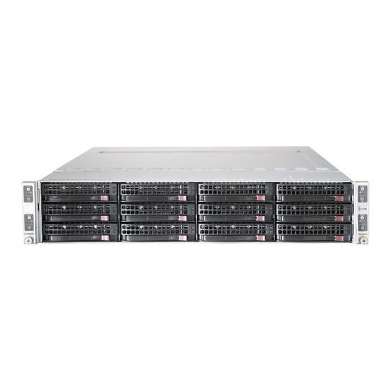
- Page 3 It provides information for the installation and use of the SuperServer 6028TP-HTR/HTTR/HTFR. Installation and maintenance should be performed by experienced technicians only. The SuperServer 6028TP-HTR/HTTR/HTFR is a high-end server based on SC827HQ+-R2K02B 2U rackmount chassis and the dual processor X10DRT-P/PT/PIBF serverboard. Both models have an IPMI LAN port and four serverboard nodes with three hot-swap Hard Disk Drives (HDD) each per node.
- Page 4 SUPERSERVER 6028TP-HTR/HTTR/HTFR USER'S MANUAL Chapter 6: Advanced Chassis Setup Refer to Chapter 6 for detailed information on the SC827HQ+-R2K02B server chassis. You should follow the procedures given in this chapter when installing, removing or reconfiguring SATA or peripheral drives and when replacing system power supply units and cooling fans.
- Page 5 SUPERSERVER 6028TP-HTR/HTTR/HTFR USER'S MANUAL Notes...
-
Page 6: Table Of Contents
SUPERSERVER 6028TP-HTR/HTTR/HTFR USER'S MANUAL Table of Contents Chapter 1 Introduction Overview ......................1-1 Serverboard Features ..................1-2 Processors ...................... 1-2 Memory ......................1-2 Serial ATA ....................... 1-2 PCI Expansion Slots ..................1-2 Onboard Controllers/Ports ................1-2 Graphics Controller ..................1-3 InfiniBand ...................... - Page 7 Table of Contents Reliable Ground ..................2-3 Installing the System into a Rack ..............2-4 Separating the Sections of the Rack Rails ............. 2-4 Installing the Inner Rail Extension ..............2-5 Outer Rack Rails ..................... 2-6 Chapter 3 System Interface Overview ......................
- Page 8 SUPERSERVER 6028TP-HTR/HTTR/HTFR USER'S MANUAL Memory Support ....................5-9 Adding PCI Expansion Cards ................5-11 Serverboard Details ..................5-12 X10DRT-P/PT/PIBF Quick Reference ............5-13 Connector Definitions ..................5-14 Jumper Settings .................... 5-17 Explanation of Jumpers ................5-17 5-10 Onboard Indicators ..................5-19 5-11 PCI-Express and SATA Connections ............
- Page 9 Table of Contents Main Setup ...................... 7-2 Advanced Setup Configurations..............7-4 Event Logs ....................7-32 IPMI ....................... 7-34 Security Settings ................... 7-36 Boot Settings ....................7-37 Save & Exit ....................7-39 Appendix A BIOS Error Beep Codes Appendix B System Specifications Appendix C Chinese Safety Warnings...
- Page 10 SUPERSERVER 6028TP-HTR/HTTR/HTFR USER'S MANUAL Notes...
-
Page 11: Chapter 1 Introduction
(www.supermicro.com). In addition to the serverboard and chassis, various hardware components have been included with the SuperServer 6028TP-HTR/HTTR/HTFR server, as listed below: • Heat Sinks... -
Page 12: Serverboard Features
Processors The X10DRT-P/PT/PIBF supports single or dual Intel® Xeon® E5-2600 v3 series processors (Socket R LGA 2011). Please refer to the serverboard description pages on our web site for a complete listing of supported processors (www.supermicro. com). Memory The X10DRT-P/PT/PIBF has sixteen DIMM slots supporting up to 1024 GB of LRDIMM (Load Reduced DIMM) or 512 GB of RDIMM (Registered DIMM) DDR4-2133/1866/1600 MHz registered ECC memory. -
Page 13: Graphics Controller
USB headers are included on the serverboard), an IPMI dedicated LAN port and two Ethernet ports. Note: For IPMI Configuration Instructions, please refer to the Embedded BMC Configuration User's Guide available at http://www.supermicro.com/support/ manuals/. Graphics Controller The X10DRT-P/PT/PIBF features an integrated ASpeed 2400 BMC with an integrated VGA/2D graphics controller. -
Page 14: Front Control Panel
SUPERSERVER 6028TP-HTR/HTTR/HTFR USER'S MANUAL Front Control Panel SC827HQ+-R2K02B chassis includes four front panels on the handles of the chassis which control each of the systems. Each control panel on the SuperServer 6028TP-HTR/HTTR/HTFR provides you with system monitoring and control for one server node. - Page 15 Chapter 1: Introduction Figure 1-1. Intel PCH C612 Chipset: System Block Diagram Note: This is a general block diagram and may not exactly repre- sent the features on your serverboard. See the previous pages for the actual specifications of your serverboard. This block diagram is intended for your reference only.
-
Page 16: Contacting Supermicro
SUPERSERVER 6028TP-HTR/HTTR/HTFR USER'S MANUAL Contacting Supermicro Headquarters Address: Super Micro Computer, Inc. 980 Rock Ave. San Jose, CA 95131 U.S.A. Tel: +1 (408) 503-8000 Fax: +1 (408) 503-8008 Email: marketing@supermicro.com (General Information) support@supermicro.com (Technical Support) Web Site: www.supermicro.com Europe Address: Super Micro Computer B.V. -
Page 17: Twin 2 : System Notes
SATA Backplane/Drives As a system, the SuperServer 6028TP-HTR/HTTR/HTFR supports the use of twelve SATA drives. A single SATA backplane works to apply system-based control for power and fan speed functions, yet at the same time logically connects a set of three SATA drives to each serverboard. - Page 18 SUPERSERVER 6028TP-HTR/HTTR/HTFR USER'S MANUAL Notes...
-
Page 19: Chapter 2 Server Installation
Unpacking the System You should inspect the box the SuperServer 6028TP-HTR/HTTR/HTFR was shipped in and note if it was damaged in any way. If the server itself shows damage you should file a damage claim with the carrier who delivered it. -
Page 20: Warnings And Precautions
SUPERSERVER 6028TP-HTR/HTTR/HTFR USER'S MANUAL Warnings and Precautions Choosing a Setup Location • Leave enough clearance in front of the rack to enable you to open the front door completely (~25 inches) and approximately 30 inches of clearance in the back of the rack to allow for sufficient airflow and ease in servicing. -
Page 21: Rack Mounting Considerations
Chapter 2: Server Installation Rack Mounting Considerations Ambient Operating Temperature If installed in a closed or multi-unit rack assembly, the ambient operating temperature of the rack environment may be greater than the ambient temperature of the room. Therefore, consideration should be given to installing the equipment in an environment compatible with the manufacturer’s maximum rated ambient temperature (Tmra). -
Page 22: Installing The System Into A Rack
SUPERSERVER 6028TP-HTR/HTTR/HTFR USER'S MANUAL Installing the System into a Rack This section provides information on installing the SC827HQ+ chassis into a rack unit with the quick-release rails provided. There are a variety of rack units on the market, which may mean the assembly procedure will differ slightly. You should also refer to the installation instructions that came with the rack unit you are using. -
Page 23: Installing The Inner Rail Extension
Chapter 2: Server Installation Installing the Inner Rail Extension The SC827HQ+ chassis includes a set of inner rails in two sections: inner rails and inner rail extensions. The inner rails are pre-attached to the chassis, and do not interfere with normal use of the chassis if you decide not to use a server rack. The inner rail extension is attached to the inner rail to mount the chassis in the rack. -
Page 24: Outer Rack Rails
SUPERSERVER 6028TP-HTR/HTTR/HTFR USER'S MANUAL Outer Rack Rails Outer rails attach to the rack and hold the chassis in place. The outer rails for the SC827HQ+ chassis extend between 30 inches and 33 inches. Installing the Outer Rails to the Rack (Figure 2-3) 1. - Page 25 Chapter 2: Server Installation Installing the Chassis into a Rack (Figure 2-4) 1. Extend the outer rails as illustrated above. 2. Align the inner rails of the chassis with the outer rails on the rack. 3. Slide the inner rails into the outer rails, keeping the pressure even on both sides.
- Page 26 SUPERSERVER 6028TP-HTR/HTTR/HTFR USER'S MANUAL Notes...
-
Page 27: Chapter 3 System Interface
Chapter 3: System Interface Chapter 3 System Interface Overview There are several LEDs on the control panel and on the drive carriers to keep you constantly informed of the overall status of the system. SC827HQ+ models include four front panels on the handles of the chassis which control each of the systems. This chapter explains the meanings of all LED indicators and the appropriate response you may need to take. -
Page 28: Control Panel Button
SUPERSERVER 6028TP-HTR/HTTR/HTFR USER'S MANUAL Control Panel Button • Power: The main power button on each of the four control panels is used to apply or remove power from the power supply to each of the four systems in the chassis. Turning off system power with this button removes the main power, but keeps standby power supplied to the system. -
Page 29: Drive Carrier Leds
Chapter 3: System Interface Drive Carrier LEDs The server chassis uses SATA drives. SATA Drives Each SATA drive carrier has two LEDs. • Blue: Each Serial ATA drive carrier has a green LED. When illuminated, this green LED (on the front of the SATA drive carrier) indicates drive activity. A connection to the SATA backplane enables this LED to blink on and off when that particular drive is being accessed. - Page 30 SUPERSERVER 6028TP-HTR/HTTR/HTFR USER'S MANUAL Notes...
-
Page 31: About Standardized Warning Statements
The following statements are industry standard warnings, provided to warn the user of situations which have the potential for bodily injury. Should you have questions or experience difficulty, contact Supermicro's Technical Support department for assistance. Only certified technicians should attempt to install or configure components. - Page 32 SUPERSERVER 6028TP-HTR/HTTR/HTFR USER'S MANUAL Warnung WICHTIGE SICHERHEITSHINWEISE Dieses Warnsymbol bedeutet Gefahr. Sie befinden sich in einer Situation, die zu Verletzungen führen kann. Machen Sie sich vor der Arbeit mit Geräten mit den Gefahren elektrischer Schaltungen und den üblichen Verfahren zur Vorbeugung vor Unfällen vertraut.
- Page 33 Chapter 4: Warning Statements for AC Systems . ٌ ا ك ً ف حالة و ٌ يك أى تتسبب ف اصابة جسذ ة ٌ هذا الزهز ع ٌ خطز !تحذ ز قبل أى تعول عىل أي هعذات،يك عىل علن بالوخاطز ال ا ٌ جوة عي الذوائز ٍ...
-
Page 34: Installation Instructions
SUPERSERVER 6028TP-HTR/HTTR/HTFR USER'S MANUAL Installation Instructions Warning! Read the installation instructions before connecting the system to the power source. 設置手順書 システムを電源に接続する前に、 設置手順書をお読み下さい。 警告 将此系统连接电源前,请先阅读安装说明。 警告 將系統與電源連接前,請先閱讀安裝說明。 Warnung Vor dem Anschließen des Systems an die Stromquelle die Installationsanweisungen lesen. ¡Advertencia! Lea las instrucciones de instalación antes de conectar el sistema a la red de alimentación. -
Page 35: Circuit Breaker
Chapter 4: Warning Statements for AC Systems Circuit Breaker Warning! This product relies on the building's installation for short-circuit (overcurrent) protection. Ensure that the protective device is rated not greater than: 250 V, 20 A. サーキッ ト ・ ブレーカー この製品は、 短絡 (過電流) 保護装置がある建物での設置を前提としています。 保護装置の定格が250 V、... -
Page 36: Power Disconnection Warning
SUPERSERVER 6028TP-HTR/HTTR/HTFR USER'S MANUAL هذا املنتج يعتمد عىل معداث الحاميت مه الدوائ ر القصرية التي تم تثبيتها يف املبنى 20A, 250V : تأكد من أن تقييم الجهاز الوقايئ ليس أكرث من 경고! 이 제품은 전원의 단락(과전류)방지에 대해서 전적으로 건물의 관련 설비에... - Page 37 Chapter 4: Warning Statements for AC Systems ¡Advertencia! El sistema debe ser disconnected de todas las fuentes de energía y del cable eléctrico quitado de los módulos de fuente de alimentación antes de tener acceso el interior del chasis para instalar o para quitar componentes de sistema. Attention Le système doit être débranché...
-
Page 38: Equipment Installation
SUPERSERVER 6028TP-HTR/HTTR/HTFR USER'S MANUAL Equipment Installation Warning! Only trained and qualified personnel should be allowed to install, replace, or service this equipment. 機器の設置 トレーニングを受け認定された人だけがこの装置の設置、 交換、 またはサービスを許可 されています。 警告 只有经过培训且具有资格的人员才能进行此设备的安装、更换和维修。 警告 只有經過受訓且具資格人員才可安裝、更換與維修此設備。 Warnung Das Installieren, Ersetzen oder Bedienen dieser Ausrüstung sollte nur geschultem, qualifiziertem Personal gestattet werden. -
Page 39: Restricted Area
Chapter 4: Warning Statements for AC Systems Waarschuwing Deze apparatuur mag alleen worden geïnstalleerd, vervangen of hersteld door geschoold en gekwalificeerd personeel. Restricted Area Warning! This unit is intended for installation in restricted access areas. A restricted access area can be accessed only through the use of a special tool, lock and key, or other means of security. -
Page 40: Battery Handling
SUPERSERVER 6028TP-HTR/HTTR/HTFR USER'S MANUAL אזור עם גישה מוגבלת !אזהרה יש להתקין את היחידה באזורים שיש בהם הגבלת גישה. הגישה ניתנת בעזרת (.'כלי אבטחה בלבד (מפתח, מנעול וכד . تخصيص هذه انىحذة نترك ب ُها ف مناطق محظورة تم ، م َ كن انىصىل إن منطقت محظورة فقط من خالل استخذاو أداة خاصت... - Page 41 Chapter 4: Warning Statements for AC Systems Warnung Bei Einsetzen einer falschen Batterie besteht Explosionsgefahr. Ersetzen Sie die Batterie nur durch den gleichen oder vom Hersteller empfohlenen Batterietyp. Entsorgen Sie die benutzten Batterien nach den Anweisungen des Herstellers. Attention Danger d'explosion si la pile n'est pas remplacée correctement. Ne la remplacer que par une pile de type semblable ou équivalent, recommandée par le fabricant.
-
Page 42: Redundant Power Supplies
SUPERSERVER 6028TP-HTR/HTTR/HTFR USER'S MANUAL Redundant Power Supplies Warning! This unit might have more than one power supply connection. All connections must be removed to de-energize the unit. 冗長電源装置 このユニッ トは複数の電源装置が接続されている場合があります。 ユニッ トの電源を切るためには、 すべての接続を取り外さなければなりません。 警告 此部件连接的电源可能不止一个,必须将所有电源断开才能停止给该部件供电。 警告 此裝置連接的電源可能不只一個,必須切斷所有電源才能停止對該裝置的供電。 Warnung Dieses Gerät kann mehr als eine Stromzufuhr haben. Um sicherzustellen, dass der Einheit kein trom zugeführt wird, müssen alle Verbindungen entfernt werden. -
Page 43: Backplane Voltage
Chapter 4: Warning Statements for AC Systems . قد يكون لهذا الجهاز عدة اتصاالت بوحدات امداد الطاقة يجب إ ز الة كافة االتصاالت لعسل الوحدة عن الكهرباء 경고! 이 장치에는 한 개 이상의 전원 공급 단자가 연결되어 있을 수 있습니다. 이 장치에 전원을... -
Page 44: Comply With Local And National Electrical Codes
SUPERSERVER 6028TP-HTR/HTTR/HTFR USER'S MANUAL מתח בפנל האחורי !אזהרה קיימת סכנת מתח בפנל האחורי בזמן תפעול המערכת. יש להיזהר במהלך .העבודה هناك خطز مه التيار الكهزبايئ أوالطاقة املىجىدة عىل اللىحة عندما يكىن النظام يعمل كه حذ ر ا عند خدمة هذا الجهاس... -
Page 45: Product Disposal
Chapter 4: Warning Statements for AC Systems Attention L'équipement doit être installé conformément aux normes électriques nationales et locales. תיאום חוקי החשמל הארצי !אזהרה .התקנת הציוד חייבת להיות תואמת לחוקי החשמל המקומיים והארציים تركيب املعدات الكهربائية يجب أن ميتثل للقىاويه املحلية والىطىية املتعلقة بالكهرباء... -
Page 46: Hot Swap Fan Warning
SUPERSERVER 6028TP-HTR/HTTR/HTFR USER'S MANUAL Attention La mise au rebut ou le recyclage de ce produit sont généralement soumis à des lois et/ou directives de respect de l'environnement. Renseignez-vous auprès de l'organisme compétent. סילוק המוצר !אזהרה .סילוק סופי של מוצר זה חייב להיות בהתאם להנחיות וחוקי המדינה... - Page 47 Chapter 4: Warning Statements for AC Systems Warnung Gefährlich Bewegende Teile. Von den bewegenden Lüfterblätter fern halten. Die Lüfter drehen sich u. U. noch, wenn die Lüfterbaugruppe aus dem Chassis genommen wird. Halten Sie Finger, Schraubendreher und andere Gegenstände von den Öffnungen des Lüftergehäuses entfernt. ¡Advertencia! Riesgo de piezas móviles.
-
Page 48: Power Cable And Ac Adapter
Electrical Appliance and Material Safety Law prohibits the use of UL or CSA -certified cables (that have UL/CSA shown on the code) for any other electrical devices than products designated by Supermicro only.. 電源コードとACアダプター 製品を設置する場合、 提供または指定および購入された接続ケーブル、 電源コードとAC アダプターを... - Page 49 -בכבלים המוסמכים בUL -או בCSA (( כאשר מופיע עליהם קוד שלUL/CSA עבור כל מוצר חשמלי אחר, אלא רק במוצר אשר הותאם ע"יSupermicro .בלבד عند تركيب املنتج، قم باستخدام التوصيالت املتوفرة أو املحددة أو قم ب رش اء الكابالت الكهربائية ومحوالت التيار...
- Page 50 Het gebruik van niet geschikte Kabels en/of Adapters kan een storing of brand veroorzaken. Wetgeving voor Elektrische apparatuur en Materiaalveiligheid verbied het gebruik van UL of CSA -gecertificeerde Kabels (met UL/CSA in de code) voor elke andere toepassing dan de door Supermicro hiervoor beoogde Producten. 4-20...
-
Page 51: Chapter 5 Advanced Serverboard Setup
Chapter 5: Advanced Serverboard Setup Chapter 5 Advanced Serverboard Setup This chapter covers the steps required to install the X10DRT-P/PT/PIBF serverboard into the chassis, connect the data and power cables and install add-on cards. All serverboard jumpers and connections are also described. A layout and quick reference chart are included in this chapter for your reference. -
Page 52: Connecting Cables
SUPERSERVER 6028TP-HTR/HTTR/HTFR USER'S MANUAL Connecting Cables Now that the processors are installed, the next step is to connect the cables to the serverboard. Connecting Data Cables The cables used to transfer data from the peripheral devices have been carefully routed in preconfigured systems to prevent them from blocking the flow of cooling air that moves through the system from front to back. -
Page 53: Rear I/O Ports
Chapter 5: Advanced Serverboard Setup Rear I/O Ports See Figure 5-1 below for the and locations of the various rear I/O ports and the UID switch. Figure 5-1. Rear I/O Ports Rear I/O Port Locations and Definitions Dedicated IPMI LAN Back Panel USB 3.0 Port 1 Back Panel USB 3.0 Port 0 Gigabit LAN 2... -
Page 54: Processor And Heatsink Installation
• Install the processor into the CPU socket before installing the heatsink. • Refer to the Supermicro web site for updates on CPU support. Installing a CPU 1. There are two levers on the LGA 2011 socket. First press and release the load lever labeled "Open 1st". - Page 55 Chapter 5: Advanced Serverboard Setup 3. With the second lever fully Open the load plate. retracted, gently push down on the "Open 1st" lever to loosen the load plate. Lift the load plate with your fingers to open it completely. IMPORTANT! 4.
- Page 56 SUPERSERVER 6028TP-HTR/HTTR/HTFR USER'S MANUAL Gently close the load plate. 7. With the "Close 1st" lever fully retracted, gently close the load plate. Push down and lock the lever labeled "Close 1st". 8. Make sure the locking mechanism on the "Close 1st" lever catches the lip of the load plate.
-
Page 57: Installing A Passive Cpu Heatsink
Chapter 5: Advanced Serverboard Setup Installing a Passive CPU Heatsink 1. Do not apply any thermal grease to the heatsink or the CPU die -- the required amount has already been applied. 2. Place the heatsink on top of the CPU so that the four mounting holes are aligned with those on the serverboard and the heatsink bracket underneath. -
Page 58: Removing The Heatsink
SUPERSERVER 6028TP-HTR/HTTR/HTFR USER'S MANUAL Removing the Heatsink Caution: We DO NOT recommend that the CPU or the heatsink be removed. However, if you do need to uninstall the heatsink, please follow the instructions below to prevent damage to the CPU or the CPU socket. -
Page 59: Installing Memory
The X10DRT-P/PT/PIBF has sixteen DIMM slots supporting up to 1024 GB of LRDIMM (Load Reduced DIMM) or 512 GB of RDIMM (Registered DIMM) DDR4-2133/1866/1600 MHz registered ECC memory. Note: Check the Supermicro website (www.supermicro.com) for the latest memory support information. Figure 5-2. DIMM Installation... - Page 60 SUPERSERVER 6028TP-HTR/HTTR/HTFR USER'S MANUAL Processor & Memory Module Population Configuration For the memory to work properly, follow the tables below when populating the DIMM slots. Processors and their Corresponding Memory Modules CPU# Corresponding DIMMs CPU 1 DIMMA1 DIMMB1 DIMMC1 DIMMD1...
-
Page 61: Adding Pci Expansion Cards
Chapter 5: Advanced Serverboard Setup Adding PCI Expansion Cards The 6028TP-HTR/HTTR/HTFR includes one preinstalled riser card per node, designed specifically for use in the SC827HQ+-R2K02B 2U rackmount chassis. This riser card supports one low-profile PCI Express x16 card to fit inside the chassis for each node. -
Page 62: Serverboard Details
SUPERSERVER 6028TP-HTR/HTTR/HTFR USER'S MANUAL Serverboard Details Figure 5-3. X10DRT-P/PT/PIBF Serverboard Layout (not drawn to scale) LAN1/LAN2 (3.0) USB0/1 IB_LINK_LED1 IPMI_LAN BIOS Slot2 Slot1 QSFP LAN CTRL 10G/1G JTPM1 CPLD JBT1 BATTERY SXB1 CPU2_VRM_HS1 CPU2 X10DRT-P Series Rev. 1.02 SXB2 CPU1 Notes •... -
Page 63: X10Drt-P/Pt/Pibf Quick Reference
Connector Description COM1 COM Port 1 FAN3/FAN4 System Fan Headers Supermicro Proprietary Slot for Add-On Card for Power, Front Control Panel JIPMB1 4-pin External BMC I C Header (for an IPMI Card) JSD1 SATA DOM (Device On Module) Power Connector... -
Page 64: Connector Definitions
SUPERSERVER 6028TP-HTR/HTTR/HTFR USER'S MANUAL Connector Definitions Main Power Main power to the serverboard is supplied through the system backplane (BPN- SAS3-827HQ), which receives power directly from the power supply. One hard drive backplane in each node (BPN-ADP-6SATA3P) plugs into system backplane and the... - Page 65 Chapter 5: Advanced Serverboard Setup Serial Port Pin Definitions (COM1) Pin # Definition Pin # Definition Serial Port The COM1 (serial) port is located on ther serverboard behind the LAN ports. See the table on the right for pin definitions. Ground VGA Port A VGA (video) port is provided on the...
- Page 66 SUPERSERVER 6028TP-HTR/HTTR/HTFR USER'S MANUAL Fan Headers This serverboard has two system fan Fan Header headers (Fan 3/Fan 4). These 4-pin Pin Definitions fans headers are backward compatible Pin# Definition with traditional 3-pin fans. However, fan Ground speed control is available for 4-pin fans +12V only.
-
Page 67: Jumper Settings
Chapter 5: Advanced Serverboard Setup Jumper Settings Connector Pins Explanation of Jumpers To modify the operation of the serverboard, Jumper jumpers can be used to choose between optional settings. Jumpers create shorts between two pins to change the function Setting of the connector. - Page 68 SUPERSERVER 6028TP-HTR/HTTR/HTFR USER'S MANUAL Watch Dog Enable/Disable Watch Dog (JWD1) is a system monitor Watch Dog that can reboot the system when a Jumper Settings software application hangs. Close pins Jumper Setting Definition 1-2 to reset the system if an application...
-
Page 69: 5-10 Onboard Indicators
Chapter 5: Advanced Serverboard Setup 5-10 Onboard Indicators LAN Port LEDs The LAN ports are located on the rear I/O LAN Port LED (Connection Speed Indicator) panel. On each Gb LAN port, one LED LED Color Definition blinks to indicate activity while the other 10 Mbps may be green, amber or off to indicate the Green... - Page 70 SUPERSERVER 6028TP-HTR/HTTR/HTFR USER'S MANUAL BMC Heartbeat LED BMC Heartbeat LED (LEM1) Status A BMC Heartbeat LED is provided to Color/State Definition display BMC status. When blinking, Green: Blinking BMC:Normal BMC is functioning normally. See the table at right for more information.
-
Page 71: 5-11 Pci-Express And Sata Connections
Chapter 5: Advanced Serverboard Setup 5-11 PCI-Express and SATA Connections S-SATA 0-2/CPU2_PCI-Express 3.0 x16 Slot (SXB1) A CPU2_PCI-Express 3.0 x16 slot and S-SATA 0-2 connections are located on the serverboard. I-SATA 0-5/CPU1_PCI-Express 3.0 x8 Slot (SXB2) A CPU1_PCI-Express 3.0 x8 slot and I-SATA 0-5 connections are located on the serverboard. -
Page 72: 5-12 Installing Software
SUPERSERVER 6028TP-HTR/HTTR/HTFR USER'S MANUAL 5-12 Installing Software The Supermicro ftp site contains drivers and utilities for your system at ftp://ftp. supermicro.com. Some of these must be installed, such as the chipset driver. After accessing the ftp site, go into the CDR_Images directory and locate the ISO file for your serverboard. -
Page 73: Superdoctor® 5
Chapter 5: Advanced Serverboard Setup SuperDoctor® 5 The Supermicro SuperDoctor 5 is a program that functions in a command-line or web-based interface in Windows and Linux operating systems. The program monitors system health information such as CPU temperature, system voltages, system power consumption, fan speed, and provides alerts via email or Simple Network Management Protocol (SNMP). -
Page 74: 5-13 Onboard Battery
SUPERSERVER 6028TP-HTR/HTTR/HTFR USER'S MANUAL 5-13 Onboard Battery Please handle used batteries carefully. Do not damage the battery in any way; a damaged battery may release hazardous materials into the environment. Do not discard a used battery in the garbage or a public landfill. Please comply with the regulations set up by your local hazardous waste management agency to dispose of your used battery properly. -
Page 75: Chapter 6 Advanced Chassis Setup
Chapter 6: Advanced Chassis Setup Chapter 6 Advanced Chassis Setup This chapter covers the steps required to install components and perform maintenance on the SC827HQ+-R2K02B chassis. For component installation, follow the steps in the order given to eliminate the most common problems encountered. If some steps are unnecessary, skip ahead to the step that follows. -
Page 76: Control Panel
SUPERSERVER 6028TP-HTR/HTTR/HTFR USER'S MANUAL Figure 6-1. Front and Rear Chassis Views Control Panel Control Panel Control Panel Control Panel SATA Drives (12) IPMI LAN Port Low-Profile PCI-E Slot Zero Slot Ethernet Ports USB Ports Infiniband Port VGA Port (6028TP-HTFR only) Control Panel The control panel is located on the front of the chassis. -
Page 77: Chassis Cover
Chapter 6: Advanced Chassis Setup Chassis Cover Before operating the SC827HQ+ chassis for the first time, it is important to remove the protective film covering the top of the chassis, in order to allow for proper ventilation and cooling. Removing the Chassis Cover and Protective Film (Figure 6-2) 1. -
Page 78: Air Shrouds
SUPERSERVER 6028TP-HTR/HTTR/HTFR USER'S MANUAL Air Shrouds Air shrouds concentrate airflow to maximize fan efficiency. The SC827HQ+ chassis air shroud does not require screws to set up. The 6028TP-HTR/HTTR/HTFR requires four identical air shrouds, one in each serverboard drawer (p/n MCP-310- 21702-0B). -
Page 79: Checking The Airflow
Chapter 6: Advanced Chassis Setup Checking the Airflow Checking Airflow 1. Make sure there are no objects to obstruct airflow in and out of the server. In addition, if you are using a front bezel, make sure the bezel's filter is replaced periodically. - Page 80 SUPERSERVER 6028TP-HTR/HTTR/HTFR USER'S MANUAL Changing a System Fan 1. If necessary, open the chassis while the power is running to determine which fan has failed. (Never run the server for an extended period of time with the chassis cover open.) 2.
- Page 81 Chapter 6: Advanced Chassis Setup Figure 6-5. Replacing a System Fan in the Fan Housing...
-
Page 82: Removing And Installing The Backplane
SUPERSERVER 6028TP-HTR/HTTR/HTFR USER'S MANUAL Removing and Installing the Backplane The SC827HQ+ chassis backplane is located behind the hard drives and in front of the front system fans. In order to change jumper settings on the backplane, it may be necessary to remove the backplane from the chassis. - Page 83 Chapter 6: Advanced Chassis Setup 7. Remove the side screw from the side of the chassis (Figure 6-7). Figure 6-7. Loosening the Spring Bar Screws in the Floor of the Chassis 8. Gently ease the backplane up and out of the chassis (Figure 6-8). Figure 6-8.
-
Page 84: Installing The Backplane
SUPERSERVER 6028TP-HTR/HTTR/HTFR USER'S MANUAL Installing the Backplane Installing the Backplane into the Chassis (Figure 6-9) 1. Ensure that all of the hard drive trays have been removed from the bays in the front of the chassis and that the spring bar has been loosened as directed in the previous section. -
Page 85: Installing The Serverboard
Chapter 6: Advanced Chassis Setup Installing the Serverboard I/O Shield The I/O shield holds the serverboard ports in place. The I/O shield does not require installation. Permanent and Optional Standoffs Standoffs prevent short circuits by securing space between the serverboard and the chassis surface. - Page 86 SUPERSERVER 6028TP-HTR/HTTR/HTFR USER'S MANUAL 8. Connect the cables between the serverboard, backplane, chassis, front panel, and power supply, as needed. Also, fans may be temporarily removed to allow access to the backplane ports. 9. Replace the add-on card bracket and secure the bracket with a screw.
-
Page 87: Adapter Card Replacement
Chapter 6: Advanced Chassis Setup Adapter Card Replacement Each serverboard drawer comes equipped with an adapter card which plugs into the backplane. In the unlikely event that the adapter card needs to be replaced, installation requires only a Phillips head screwdriver. Figure 6-11. -
Page 88: Add-On Card/Expansion Slot Setup
SUPERSERVER 6028TP-HTR/HTTR/HTFR USER'S MANUAL Add-on Card/Expansion Slot Setup The SC827HQ+ chassis includes I/O slots for add-on cards and expansion cards. Each side supports one low profile/half length add-on card for a total of four per chassis, one per drawer. Installing Add-on Cards (Figure 6-12) 1. -
Page 89: 6-10 Drive Bay Installation/Removal
SATA drives. Proceed to the next step for instructions. You must use standard 1" high, SATA drives in the system. Note: Refer to Supermicro's web site for setup guidelines: <http://www.supermicro. com/support/manuals/>. The SC827HQ+ chassis contains four individual serverboards in separate node drawers (Figure 6-13). - Page 90 SUPERSERVER 6028TP-HTR/HTTR/HTFR USER'S MANUAL Removing Hard Drive Trays from the Chassis (Figure 6-14) 1. Press the release button on the drive tray. This extends the drive bay handle. 2. Use the handle to pull the drive out of the chassis.
- Page 91 Chapter 6: Advanced Chassis Setup The drives are mounted in drive carriers to simplify their installation and removal from the chassis (Figure 6-15). These carriers also help promote proper airflow for the drive bays. Figure 6-15. Chassis Drive Tray Dummy Drive Drive Tray Installing a Drive into the Hard Drive Tray 1.
- Page 92 Figure 6-17. Installing the Hard Drive SATA Hard Drive Drive Tray Caution: Enterprise level hard disk drives are recommended for use in Supermicro chassis and servers. For information on recommended HDDs, visit the Supermicro website at http://www.supermicro.com/products/nfo/files/storage/SAS-CompList.pdf 6-18...
-
Page 93: 6-11 Power Supply
Replacement units can be ordered directly from Supermicro (See the contact information in the Preface of this manual). Changing the Power Supply (Figure 6-18) 1. - Page 94 SUPERSERVER 6028TP-HTR/HTTR/HTFR USER'S MANUAL Figure 6-18. Changing the Power Supply Release Tab 6-20...
-
Page 95: Chapter 7 Bios
When an option is selected in the left frame, it is highlighted in white. Often a text message will accompany it. Note: the AMI BIOS has default text messages built in. Supermicro retains the option to include, omit, or change any of these text messages. -
Page 96: How To Start The Setup Utility
Flashing the wrong BIOS can cause irreparable damage to the system. In no event shall Supermicro be liable for direct, indirect, special, incidental, or consequential damages arising from a BIOS update. If you have to update the BIOS, do not shut down or reset the system while the BIOS is updating to avoid possible boot failure. - Page 97 Day MM/DD/YYYY format. The time is entered in HH:MM:SS format. Note: The time is in the 24-hour format. For example, 5:30 P.M. appears as 17:30:00. Supermicro X10DRT-P Series BIOS Version: This item displays the version of the BIOS ROM used in the system.
-
Page 98: Advanced Setup Configurations
SUPERSERVER 6028TP-HTR/HTTR/HTFR USER'S MANUAL Advanced Setup Configurations Use the arrow keys to select Advanced setup and press <Enter> to access the submenu items: Warning: Take Caution when changing the Advanced settings. An incorrect value, a very high DRAM frequency or an incorrect BIOS timing setting may cause the system to malfunction. - Page 99 Chapter 7: BIOS Wait For 'F1' If Error Select Enabled to force the system to wait until the 'F1' key is pressed if an error occurs. The options are Disabled and Enabled. INT19 (Interrupt 19) Trap Response Interrupt 19 is the software interrupt that handles the boot disk function. When this item is set to Immediate, the ROM BIOS of the host adaptors will "capture"...
- Page 100 SUPERSERVER 6028TP-HTR/HTTR/HTFR USER'S MANUAL CPU Configuration This submenu displays the following CPU information as detected by the BIOS. It also allows the user to configure CPU settings. • Processor Socket • Processor ID • Processor Frequency • Processor Max Ratio •...
- Page 101 Chapter 7: BIOS Hardware Prefetcher (Available when supported by the CPU) If set to Enable, the hardware prefetcher will prefetch streams of data and instruc- tions from the main memory to the L2 cache to improve CPU performance. The options are Disable and Enable. Adjacent Cache Line Prefetch (Available when supported by the CPU) Select Enable for the CPU to prefetch both cache lines for 128 bytes as comprised.
- Page 102 SUPERSERVER 6028TP-HTR/HTTR/HTFR USER'S MANUAL X2 APIC (Advanced Programmable Interrupt Controller) Based on Intel's Hyper-Threading architecture, each logical processor (thread) is assigned 256 APIC IDs (APIDs) in 8-bit bandwidth. When this feature is set to En- able, the APIC ID will be expanded (X2) from 8 bits to 16 bits to provide 512 APIDs to each thread to enhance CPU performance.
- Page 103 Chapter 7: BIOS P-state Coordination This feature is used to change the P-state (Power-Performance State) coordi- nation type. P-state is also known as "SpeedStep" for Intel processors. Select HW_ALL to change the P-state coordination type for hardware components only. Select SW_ALL to change the P-state coordination type for all software installed in the system.
- Page 104 SUPERSERVER 6028TP-HTR/HTTR/HTFR USER'S MANUAL Chipset Configuration Warning! Please set the correct settings for the items below. A wrong configuration setting may cause the system to become malfunction. North Bridge This feature allows the user to configure the settings for the Intel North Bridge.
- Page 105 Chapter 7: BIOS IOU0 (II0 PCIe Port 2) This item configures the PCI-E port Bifuraction setting for a PCI-E port specified by the user. The options are x4x4x4x4, x4x4x8, x8x4x4, x8x8, x16, and Auto. PORT 2A Link Speed This item configures the link speed of a PCI-E port specified by the user. The options are Gen 1 (Generation 1) (2.5 GT/s), Gen 2 (Generation 2) (5 GT/s), and Gen 3 (Generation 3) (8 GT/s).
- Page 106 SUPERSERVER 6028TP-HTR/HTTR/HTFR USER'S MANUAL Intel VT for Directed I/O (VT-d) Intel VT for Direct I/O (VT-d) Intel VT for Directed I/O (VT-d) ® Select Enable to use Intel Virtualization Technology support for Direct I/O VT-d support by reporting the I/O device assignments to the VMM (Virtual Machine Monitor) through the DMAR ACPI tables.
- Page 107 Chapter 7: BIOS Link Speed Mode Use this item to select the data transfer speed for QPI Link connections. The options are Fast and Slow. Link Frequency Select Use this item to select the desired frequency for QPI Link connections. The op- tions are 6.4GB/s, 8.0GB/s, 9.6GB/s, Auto, and Auto Limited.
- Page 108 SUPERSERVER 6028TP-HTR/HTTR/HTFR USER'S MANUAL Data Scrambling Select Enabled to enable data scrambling to enhance system performance and data integrity. The options are Auto, Disabled and Enabled. DRAM RAPL (Running Average Power Limit) Baseline Use this feature to set the run-time power-limit baseline for DRAM modules. The options are Disable, DRAM RAPL Mode 0, and DRAM RAPL Mode 1.
- Page 109 Chapter 7: BIOS the same set of operations in parallel to boost performance. The options are Disable, Mirror, and Lockstep Mode. Lockstep x4 DIMMs Select Enable to enable Lockstep support for x4 DIMM modules. The options are Auto, Disabled, and Enabled. Memory Rank Sparing Select Enable to enable memory-sparing support for memory ranks to improve memory performance.
- Page 110 SUPERSERVER 6028TP-HTR/HTTR/HTFR USER'S MANUAL South Bridge The following South Bridge information will display: USB Configuration • USB Module Version • USB Devices Legacy USB Support Select Enabled to support onboard legacy USB devices. Select Auto to disable legacy support if there are no legacy USB devices present. Select Disabled to have all USB devices available for EFI applications only.
- Page 111 Chapter 7: BIOS EHCI2 Select Enabled to enable EHCI (Enhanced Host Controller Interface) support on USB 3.0 connector #2. (At least one USB 3.0 connector should be enabled for EHCI support.) The options are Disabled and Enabled. XHCI Pre-Boot Drive Select Enabled to enable XHCI (Extensible Host Controller Interface) support on a pre-boot drive specified by the user.
- Page 112 SUPERSERVER 6028TP-HTR/HTTR/HTFR USER'S MANUAL SATA Configuration When this submenu is selected, AMI BIOS automatically detects the presence of the SATA devices that are supported by the Intel PCH chip and displays the fol- lowing items: SATA Controller This item enables or disables the onboard SATA controller supported by the Intel PCH chip.
- Page 113 Chapter 7: BIOS Port 0 ~ Port 5 SATA Device Type Use this item to specify if the SATA port specified by the user should be con- nected to a Solid State drive or a Hard Disk Drive. The options are Hard Disk Drive and Solid State Drive.
- Page 114 SUPERSERVER 6028TP-HTR/HTTR/HTFR USER'S MANUAL Port 0 ~ Port 5 Hot Plug Select Enabled to enable hot-plugging support for a port specified by the user, which will allow the user to replace a SATA disk drive installed on this port without shutting down the system.
- Page 115 Chapter 7: BIOS • Software Preserve Support sSATA Port 0~ Port 3 Select Enabled to enable an sSATA port specified by the user. The options are Disabled and Enabled. sSATA Port 0 ~ Port 3 Hot Plug Select Enabled to enable hot-plugging support for a port specified by the user, which will allow the user to replace a sSATA disk drive installed on this port without shutting down the system.
- Page 116 SUPERSERVER 6028TP-HTR/HTTR/HTFR USER'S MANUAL sSATA RAID Option ROM/UEFI Driver Select EFI to load the EFI driver for system boot. Select Legacy to load a legacy driver for system boot. The options are Disabled, EFI, and Legacy. sSATA Port 0~ Port 3 This item displays the information detected on the installed sSATA drives on the particular sSATA port.
- Page 117 Chapter 7: BIOS • ME Firmware Status #2 • Current State • Error Code PCIe/PCI/PnP Configuration The following PCI information will be displayed: • PCI Bus Driver Version • PCI Device Common Settings PCI Latency Timer Use this item to configure the PCI latency timer for a device installed on a PCI bus. Select 32 to set the PCI latency timer to 32 PCI clock cycles.
- Page 118 SUPERSERVER 6028TP-HTR/HTTR/HTFR USER'S MANUAL Maximum Read Request Select Auto for the system BIOS to automatically set the maximum size for a read request for a PCI-E device to enhance system performance. The options are Auto, 128 Bytes, 256 Bytes, 512 Bytes, 1024 Bytes, 2048 Bytes, and 4096 Bytes.
- Page 119 Chapter 7: BIOS Network Stack Select Enabled to enable PXE (Preboot Execution Environment) or UEFI (Uni- fied Extensible Firmware Interface) for network stack support. The options are Enabled and Disabled. Super IO Configuration Super IO Chip AST2400 Serial Port 1 Configuration/Serial Port 2 Configuration ...
- Page 120 SUPERSERVER 6028TP-HTR/HTTR/HTFR USER'S MANUAL *If the item above set to Enabled, the following items will become available for configuration: COM1 Console Redirection Settings Terminal Type This feature allows the user to select the target terminal emulation type for Con- sole Redirection. Select VT100 to use the ASCII Character set. Select VT100+ to add color and function key support.
- Page 121 Chapter 7: BIOS VT-UTF8 Combo Key Support Select Enabled to enable VT-UTF8 Combination Key support for ANSI/VT100 terminals. The options are Enabled and Disabled. Recorder Mode Select Enabled to capture the data displayed on a terminal and send it as text messages to a remote server.
- Page 122 SUPERSERVER 6028TP-HTR/HTTR/HTFR USER'S MANUAL SOL/COM2 Console Redirection Settings Use this feature to specify how the host computer will exchange data with the client computer, which is the remote computer used by the user. Terminal Type Use this feature to select the target terminal emulation type for Console Redirec- tion.
- Page 123 Chapter 7: BIOS VT-UTF8 Combo Key Support Select Enabled to enable VT-UTF8 Combination Key support for ANSI/VT100 terminals. The options are Enabled and Disabled. Recorder Mode Select Enabled to capture the data displayed on a terminal and send it as text messages to a remote server.
- Page 124 SUPERSERVER 6028TP-HTR/HTTR/HTFR USER'S MANUAL EMS Console Redirection Settings (Available when EMS Console Redirection is enabled) Use this feature to specify how the host computer will exchange data with the client computer, which is the remote computer used by the user.
- Page 125 Chapter 7: BIOS port to enhance data integrity and network security. Please reboot the system for a change on this setting to take effect. The options are Enabled and Disabled. TPM State Select Enabled to use TPM (Trusted Platform Module) settings to enhance system data security.
-
Page 126: Event Logs
SUPERSERVER 6028TP-HTR/HTTR/HTFR USER'S MANUAL Event Logs Use this feature to configure Event Log settings. Change SMBIOS Event Log Settings This feature allows the user to configure SMBIOS Event settings. Enabling/Disabling Options SMBIOS Event Log Select Enabled to enable SMBIOS (System Management BIOS) Event Logging during system boot. - Page 127 Chapter 7: BIOS Erasing Settings Erase Event Log Select Yes to erase all error events in the SMBIOS (System Management BIOS) log before an event logging is initialized at bootup. The options are No and Yes. When Log is Full Select Erase Immediately to immediately erase all errors in the SMBIOS event log when the event log is full.
-
Page 128: Ipmi
SUPERSERVER 6028TP-HTR/HTTR/HTFR USER'S MANUAL IPMI Use this feature to configure Intelligent Platform Management Interface (IPMI) settings. BMC (BaseBoard Management Controller) Firmware Revision This item indicates the BMC firmware revision used in your system. IPMI Status This item indicates the status of the IPMI firmware installed in your system. - Page 129 Chapter 7: BIOS When SEL is Full This feature allows the user to determine what the AMI BIOS should do when the system event log is full. Select Erase Immediately to erase all events in the log when the system event log is full. The options are Do Nothing and Erase Immediately. Note: After making changes on a setting, be sure to reboot the system for the changes to take effect.
-
Page 130: Security Settings
SUPERSERVER 6028TP-HTR/HTTR/HTFR USER'S MANUAL Security Settings This menu allows the user to configure the following security settings for the system. Password Check Select Setup for the system to prompt for a password upon entering the BIOS setup utility. Select Always for the system to prompt for a password at bootup and upon entering the BIOS Setup utility. -
Page 131: Boot Settings
Chapter 7: BIOS Boot Settings Use this feature to configure Boot Settings: Boot Configuration Setup Prompt Timeout Use this item to indicate how many seconds the system shall wait for the BIOS setup activation key to respond before the system starts to boot. The default setting is 1. Boot Mode Select Use this item to select the type of device to be used for system boot. - Page 132 SUPERSERVER 6028TP-HTR/HTTR/HTFR USER'S MANUAL • Dual Boot Order #7 • Dual Boot Order #8 • Dual Boot Order #9 • Dual Boot Order #10 • Dual Boot Order #11 • Dual Boot Order #12 • Dual Boot Order #13 •...
-
Page 133: Save & Exit
Chapter 7: BIOS Save & Exit Select the Save & Exit tab from the BIOS setup screen to configure the settings below. Discard Changes and Exit Select this option to quit the BIOS setup without making any permanent changes to the system configuration, and reboot the computer. Select Discard Changes and Exit from the Exit menu and press <Enter>. - Page 134 SUPERSERVER 6028TP-HTR/HTTR/HTFR USER'S MANUAL Restore Defaults Select this item and press <Enter> to load the manufacture default settings which are designed for maximum system performance but not for maximum stability. Save As User Defaults Select this item and press <Enter> to save the current BIOS settings as user's default settings for future use.
-
Page 135: Appendix A Bios Error Beep Codes
Appendix A: BIOS Error Beep Codes Appendix A BIOS Error Beep Codes During the POST (Power-On Self-Test) routines, which are performed each time the system is powered on, errors may occur. Non-fatal errors are those which, in most cases, allow the system to continue the boot-up process. - Page 136 SUPERSERVER 6028TP-HTR/HTFR USER'S MANUAL Notes...
-
Page 137: Appendix B System Specifications
LRDIMM (Load Reduced DIMM) or 512 GB of RDIMM (Registered DIMM) DDR4-2133/1866/1600 MHz registered ECC memory Note: refer to Section 5-6 for details on installation. Note: check the Supermicro website (www.supermicro.com) for the latest memory support information. SATA Drive Bays... - Page 138 SUPERSERVER 6028TP-HTR/HTTR/HTFR USER'S MANUAL Chassis SC827HQ+-R2K02B (2U rackmount) Dimensions: (WxHxD) 17.25 x 3.47 x 30 in. (438 x 88 x 762 mm) Weight Gross: 90 lbs. (40.9 kg.) System Cooling The system has four (4) 8-cm PWM system cooling fans...
- Page 139 Appendix B: System Specifications Notes...
- Page 140 SUPERSERVER 6028TP-HTR/HTTR/HTFR USER'S MANUAL (continued from front) The products sold by Supermicro are not intended for and will not be used in life support systems, medical equipment, nuclear facilities or systems, aircraft, aircraft devices, aircraft/emergency communication devices or other critical systems whose failure to perform be reasonably expected to result in significant injury or loss of life or catastrophic property damage.
-
Page 141: Appendix C Chinese Safety Warnings
Appendix C: Chinese Safety Warnings Appendix C Chinese Safety Warnings... - Page 142 SUPERSERVER 6028TP-HTR/HTTR/HTFR USER'S MANUAL 限用物質含有情況標示聲明書 Declaration of the Presence Condition of the Restricted Substances Marking 設備名稱:伺服器/Server Equipment name: 型號(型式):217-20 Type designation (Type) (系列型號: SYS-6028TP-HTR/SYS-6028TP-HTTR/SYS-6028TP-HTFR) 限用物質及其化學符號 Restricted substances and its chemical symbols 六價鉻 多溴聯苯 多溴二苯醚 單元 Unit Hexavalent Polybrominated Polybrominated 鉛Lead 汞Mercury...
Need help?
Do you have a question about the SUPERSERVER 6028TP-HTR and is the answer not in the manual?
Questions and answers