
Related Manuals for Supermicro SuperServer 6026TT-HTRF


Summary of Contents for Supermicro SuperServer 6026TT-HTRF
- Page 1 ® UPER SuperServer 6026TT-HTF SuperServer 6026TT-HTRF SuperServer 6026TT-HIBXF SuperServer 6026TT-HIBXRF SuperServer 6026TT-HIBQF SuperServer 6026TT-HIBQRF USER'S MANUAL Revision 1.0d...
- Page 2 This product, including software and documentation, is the property of Supermicro and/or its licensors, and is supplied only under a license. Any use or reproduction of this product is not allowed, except as expressly permitted by the terms of said license.
-
Page 3: About This Manual
Preface Preface About This Manual This manual is written for professional system integrators and PC technicians. It provides information for the installation and use of the SuperServer 6026TT-HT(R)F/HIBX(R)F/HIBQ(R)F. Installation and maintenance should be performed by experienced technicians only. The SuperServer 6026TT-HT(R)F/HIBX(R)F/HIBQ(R)F is a 2U Twin (four serverboards/nodes in a 2U chassis) rackmount server based on the SC827H-(R)1400B server chassis and six serverboards (Super X8DTT-H(F)/HIBX(F)/HIBQ(F)) An... - Page 4 SUPERSERVER 6026TT-HT(R)F/HIBX(R)F/HIBQ(R)F User's Manual Chapter 3: System Interface Refer to this chapter for details on the system interface, which includes the functions and information provided by the control panel on the chassis as well as other LEDs located throughout the system. Chapter 4: System Safety You should thoroughly familiarize yourself with this chapter for a general overview of safety precautions that should be followed when installing and servicing the...
- Page 5 Preface Notes...
-
Page 6: Table Of Contents
Cooling System ....................1-5 Advanced Power Management (for -F Models Only) ........1-6 Intel® Intelligent Power Node Manager (NM) ..........1-6 Manageability Engine (ME) ................1-6 Contacting Supermicro ..................1-7 2U Twin : System Notes ................. 1-8 Nodes ......................1-8 System Power .................... - Page 7 Table of Contents Reduced Airfl ow ..................2-3 Mechanical Loading ................... 2-3 Circuit Overloading ..................2-3 Reliable Ground ..................2-4 Removing the Protective Film ................. 2-4 Rack Mounting Instructions ................2-5 Separating the Sections of the Rack Rails ............. 2-5 Installing the Inner Rail Extensions ..............
- Page 8 SUPERSERVER 6026TT-HT(R)F/HIBX(R)F/HIBQ(R)F USER'S MANUAL Chapter 5 Advanced Serverboard Setup Handling the Serverboard ................5-1 Precautions ..................... 5-1 Unpacking ....................... 5-1 Serverboard Installation .................. 5-2 Connecting Cables ..................5-2 Connecting Data Cables ................. 5-3 Connecting Power Cables ................5-3 Connecting the Control Panel ................. 5-3 I/O Ports ......................
- Page 9 Table of Contents Air Shrouds ..................... 6-9 Power Supply ....................6-9 Power Supply Failure: Single Power Supply Module ........6-9 Power Supply Failure: Redundant Power (Two Modules) ......6-10 Chapter 7 BIOS Introduction ...................... 7-1 Starting BIOS Setup Utility ................7-1 How To Change the Confi...
- Page 10 SUPERSERVER 6026TT-HT(R)F/HIBX(R)F/HIBQ(R)F USER'S MANUAL Notes...
-
Page 11: Chapter 1 Introduction
X8DTT-H(F)/HIBX(F)/HIBQ(F) serverboards. Please refer to our web site for information on operating systems that have been certified for use with the SuperServer 6026TT-HT(R)F/HIBX(R)F/HIBQ(R)F (www.supermicro.com). In addition to the serverboard and chassis, various hardware components may have been included with the system, as listed below. -
Page 12: Serverboard Features
Each X8DTT-H(F)/HIBX(F)/HIBQ(F) supports two Intel® 5500/5600 series processors in LGA 1366 sockets (up to 95w). Please refer to our web site for a complete listing of supported processors (www.supermicro.com). Memory Each X8DTT-H(F)/HIBX(F)/HIBQ(F) has twelve (12) DIMM sockets that can support... -
Page 13: Ethernet Ports
Chapter 1: Introduction Ethernet Ports An Intel® network controller is integrated into each of the serverboards to support two Gigabit LAN ports (100/1000Base-T/1000BaseTX, RJ45 output). Onboard Controllers/Ports Onboard I/O backpanel ports on each serverboard include one COM port, a VGA port, two USB ports, a dedicated IPMI LAN port and two Gigabit LAN (NIC) ports. - Page 14 SUPERSERVER 6026TT-HT(R)F/HIBX(R)F/HIBQ(R)F USER'S MANUAL PROCESSOR#0 PROCESSOR#1 Intel MT25408 82574 Connect-X IB QSFP PCI-E Gen2/DDR or QDR (For 36D Only) Intel 5520/5500 82574 36-D/24-D PCI-E x16 Slot AT25 DF321 ICH10R 4 SATA Hotswap Connector LPCIO W83527 BMC/VGA RMII VGA CONN RTL8201N PHY Dedicated LAN Figure 1-1.
-
Page 15: Server Chassis Features
Chapter 1: Introduction Server Chassis Features The following is a general outline of the main features of the SC827H-(R)1400B 2U chassis. Details on the chassis can be found in Chapter 6. System Power When confi gured as a SuperServer 6026TT-HT(R)F/HIBX(R)F/HIBQ(R)F, the SC827H-(R)1400B includes a single 1400 Watt power supply, which provides power to all four serverboards (nodes). -
Page 16: Advanced Power Management (For -F Models Only)
SUPERSERVER 6026TT-HT(R)F/HIBX(R)F/HIBQ(R)F USER'S MANUAL Advanced Power Management (for -F Models Only) Intel® Intelligent Power Node Manager (NM) ® The Intel Intelligent Power Node Manager (IPNM) provides your system with real-time thermal control and power management for maximum energy effi ciency. Although IPNM Specifi... -
Page 17: Contacting Supermicro
Chapter 1: Introduction Contacting Supermicro Headquarters Address: Super Micro Computer, Inc. 980 Rock Ave. San Jose, CA 95131 U.S.A. Tel: +1 (408) 503-8000 Fax: +1 (408) 503-8008 Email: marketing@supermicro.com (General Information) support@supermicro.com (Technical Support) Web Site: www.supermicro.com Europe Address: Super Micro Computer B.V. -
Page 18: Twin 2 : System Notes
SUPERSERVER 6026TT-HT(R)F/HIBX(R)F/HIBQ(R)F USER'S MANUAL 2U Twin : System Notes As a 2U Twin confi guration, the SuperServer 6026TT-HT(R)F/HIBX(R)F/HIBQ(R)F is a unique server system. With four system boards incorporated into a single chassis acting as four separate nodes, there are several points you should keep in mind. -
Page 19: Chapter 2 Server Installation
Chapter 2: Server Installation Chapter 2 Server Installation Overview This chapter provides a quick setup checklist to get the SuperServer 6026TT-HT(R)F/HIBX(R)F/HIBQ(R)F up and running. Following these steps in the order given should enable you to have the system operational within a minimum amount of time. -
Page 20: Choosing A Setup Location
SUPERSERVER 6026TT-HT(R)F/HIBX(R)F/HIBQ(R)F USER'S MANUAL Choosing a Setup Location • Leave enough clearance in front of the rack to enable you to open the front door completely (~25 inches). • Leave approximately 30 inches of clearance in the back of the rack to allow for suffi... -
Page 21: Rack Mounting Considerations
Chapter 2: Server Installation • Make sure all power and data cables are properly connected and not blocking the chassis airfl ow. See Chapter 5 for details on cable connections. Rack Mounting Considerations Warning! To prevent bodily injury when mounting or servicing this unit in a rack, you must take special precautions to ensure that the system remains stable. -
Page 22: Reliable Ground
SUPERSERVER 6026TT-HT(R)F/HIBX(R)F/HIBQ(R)F USER'S MANUAL Reliable Ground A reliable ground must be maintained at all times. To ensure this, the rack itself should be grounded. Particular attention should be given to power supply connections other than the direct connections to the branch circuit (i.e. the use of power strips, etc.). -
Page 23: Rack Mounting Instructions
Chapter 2: Server Installation Rack Mounting Instructions Warning: Do not pick up the server with the front handles. They are designed to pull the system from a rack only. Stability Hazard: The rack stabilizing mechanism must be in place, or the rack must be bolted to the fl... -
Page 24: Installing The Inner Rail Extensions
SUPERSERVER 6026TT-HT(R)F/HIBX(R)F/HIBQ(R)F USER'S MANUAL Installing the Inner Rail Extensions The SC827 chassis includes a set of inner rails in two sections: inner rails and inner rail extensions. The inner rails are pre-attached to the chassis, and do not interfere with normal use of the chassis if you decide not to use a server rack. The inner rail extension is attached to the inner rail to mount the chassis in the rack. -
Page 25: Outer Rack Rails
Chapter 2: Server Installation Figure 2-4: Assembling the Outer Rails Outer Rack Rails Outer rails attach to the rack and hold the chassis in place. The outer rails for the SC827 chassis extend between 30 inches and 33 inches. Installing the Outer Rails to the Rack 1. - Page 26 SUPERSERVER 6026TT-HT(R)F/HIBX(R)F/HIBQ(R)F USER'S MANUAL Figure 2-5: Installing Into the Rack Installing the Chassis into a Rack 1. Extend the outer rails as illustrated above. 2. Align the inner rails of the chassis with the outer rails on the rack. 3. Slide the inner rails into the outer rails, keeping the pressure even on both sides.
-
Page 27: Checking The Serverboard Setup
Chapter 2: Server Installation Checking the Serverboard Setup After you install the system in the rack, you will need to access the inside of the nodes to make sure the serverboard is properly installed. Accessing the Inside of a Node (Figure 2-6) 1. -
Page 28: Preparing To Power On
SUPERSERVER 6026TT-HT(R)F/HIBX(R)F/HIBQ(R)F USER'S MANUAL Preparing to Power On Next, you should check to make sure the SATA drives and SATA backplane have been properly installed and all connections have been made. Checking the SATA drives 1. The SATA disk drives are accessable from the front of the server and can be installed and removed from the front of the chassis without removing the top chassis cover. - Page 29 Chapter 2: Server Installation Figure 2-6. Removing a Node from the System 2-11...
- Page 30 SUPERSERVER 6026TT-HT(R)F/HIBX(R)F/HIBQ(R)F USER'S MANUAL Notes 2-12...
-
Page 31: Chapter 3 System Interface
Chapter 3: System Interface Chapter 3 System Interface Overview There are LEDs on the control panels and on the SATA drive carriers to keep you constantly informed of the overall status of the system as well as the activity and health of specifi... -
Page 32: Control Panel Leds
SUPERSERVER 6026TT-HT(R)F/HIBX(R)F/HIBQ(R)F USER'S MANUAL Control Panel LEDs In addition to the LEDs built into the power and UID buttons, each of the four control panels located on the front of the SC827H-(R)1400B chassis has two LEDs that provide you with critical information related their own node. This section explains what each LED indicates when illuminated and any corrective action you may need to take. -
Page 33: Chapter 4 Standardized Warning Statements For Ac Systems
Only certifi ed technicians should attempt to install or confi gure components. Read this appendix in its entirety before installing or confi guring components in the Supermicro chassis. These warnings may also be found on our web site at http://www.supermicro.com/ about/policies/safety_information.cfm. Warning Defi nition Warning! This warning symbol means danger. - Page 34 SUPERSERVER 6026TT-HT(R)F/HIBX(R)F/HIBQ(R)F USER'S MANUAL Warnung WICHTIGE SICHERHEITSHINWEISE Dieses Warnsymbol bedeutet Gefahr. Sie befi nden sich in einer Situation, die zu Verletzungen führen kann. Machen Sie sich vor der Arbeit mit Geräten mit den Gefahren elektrischer Schaltungen und den üblichen Verfahren zur Vorbeugung vor Unfällen vertraut.
- Page 35 Warning Statements for AC Systems ﺟﺴﺪﻳﺔ ﺍﺻﺎﺑﺔ ﺗﺘﺴﺒﺐ ﻓﻲ ﺣﺎﻟﺔ ﻳﻤﻜﻦ ﺃﻥ ﺍﻧﻚ ﻓﻲ ﺧﻄﺮ ﻳﻌﻨﻲ ﻫﺬﺍ ﺍﻟﺮﻣﺰ !ﺗﺤﺬﻳﺮ ﺍﻟﺪﻭﺍﺋﺮ ﺑﺎﻟﻤﺨﺎﻁﺮ ﺍﻟﻨﺎﺟﻤﺔ ﻋﻦ ﻦ ﻋﻠﻰ ﻋﻠﻢ ، ﻛ ﻣﻌﺪﺍﺕ ﺗﻌﻤﻞ ﻋﻠﻰ ﺃﻱ ﻗﺒﻞ ﺃﻥ ﺍﻟﻜﻬﺮﺑﺎﺋﻴﺔ ﺣﻮﺍﺩﺙ ﺃﻱ ﻭﻗﻮﻉ ﻤﻨﻊ ﻟ ﺍﻟﻮﻗﺎﺋﻴﺔ...
-
Page 36: Installation Instructions
SUPERSERVER 6026TT-HT(R)F/HIBX(R)F/HIBQ(R)F USER'S MANUAL Installation Instructions Warning! Read the installation instructions before connecting the system to the power source. 設置手順書 システムを電源に接続する前に、 設置手順書をお読み下さい。 警告 将此系统连接电源前,请先阅读安装说明。 警告 將系統與電源連接前,請先閱讀安裝說明。 Warnung Vor dem Anschließen des Systems an die Stromquelle die Installationsanweisungen lesen. ¡Advertencia! Lea las instrucciones de instalación antes de conectar el sistema a la red de alimentación. -
Page 37: Circuit Breaker
Chapter 4: Warning Statements for AC Systems Circuit Breaker Warning! This product relies on the building's installation for short-circuit (overcurrent) protection. Ensure that the protective device is rated not greater than: 250 V, 20 A. サーキッ ト ・ ブレーカー この製品は、 短絡 (過電流) 保護装置がある建物での設置を前提としています。 保護装置の定格が250 V、... -
Page 38: Power Disconnection Warning
SUPERSERVER 6026TT-HT(R)F/HIBX(R)F/HIBQ(R)F USER'S MANUAL ﻓﻲ ﺍﻟﺘﻲ ﺗﻢ ﺗﺜﺒﻴﺘﻬﺎ ﻣﻦ ﺍﻟﺪﻭﺍﺋﺮﺍﻟﻘﺼﻴﺮﺓ ﺍﻟﺤﻤﺎﻳﺔ ﻣﻌﺪﺍﺕ ﻳﻌﺘﻤﺪ ﻋﻠﻰ ﻫﺬﺍ ﺍﻟﻤﻨﺘﺞ ﺍﻟﻤﺒﻨﻰ ﺃﻛﺜﺮ ﻣﻦ ﻟﻴﺲ ﻮﻗﺎﺋﻲ ﺍﻟ ﺍﻟﺠﻬﺎﺯ ﺗﻘﻴﻴﻢ ﺃﻥ ﺗﺄﻛﺪ ﻣﻦ 20A, 250V 경고! 이 제품은 전원의 단락(과전류)방지에 대해서 전적으로 건물의 관련 설비에 의존합니다. 보호장치의 정격이 반드시 250V(볼트), 20A(암페어)를 초과하지 않도록... - Page 39 Chapter 4: Warning Statements for AC Systems Warnung Das System muss von allen Quellen der Energie und vom Netzanschlusskabel getrennt sein, das von den Spg.Versorgungsteilmodulen entfernt wird, bevor es auf den Chassisinnenraum zurückgreift, um Systemsbestandteile anzubringen oder zu entfernen. ¡Advertencia! El sistema debe ser disconnected de todas las fuentes de energía y del cable eléctrico quitado de los módulos de fuente de alimentación antes de tener acceso el interior del chasis para instalar o para quitar componentes de sistema.
-
Page 40: Equipment Installation
SUPERSERVER 6026TT-HT(R)F/HIBX(R)F/HIBQ(R)F USER'S MANUAL Equipment Installation Warning! Only trained and qualifi ed personnel should be allowed to install, replace, or service this equipment. 機器の設置 トレーニングを受け認定された人だけがこの装置の設置、 交換、 またはサービスを許可 されています。 警告 只有经过培训且具有资格的人员才能进行此设备的安装、更换和维修。 警告 只有經過受訓且具資格人員才可安裝、更換與維修此設備。 Warnung Das Installieren, Ersetzen oder Bedienen dieser Ausrüstung sollte nur geschultem, qualifi... -
Page 41: Restricted Area
Chapter 4: Warning Statements for AC Systems Waarschuwing Deze apparatuur mag alleen worden geïnstalleerd, vervangen of hersteld door geschoold en gekwalifi ceerd personeel. Restricted Area Warning! This unit is intended for installation in restricted access areas. A restricted access area can be accessed only through the use of a special tool, lock and key, or other means of security. -
Page 42: Battery Handling
SUPERSERVER 6026TT-HT(R)F/HIBX(R)F/HIBQ(R)F USER'S MANUAL אזור עם גישה מוגבלת !אזהרה יש להתקין את היחידה באזורים שיש בהם הגבלת גישה. הגישה ניתנת בעזרת .('כלי אבטחה בלבד )מפתח, מנעול וכד ﻣﺤﻈﻮﺭﺓ ﻣﻨﺎﻁﻖ ﻟﺘﺮﻛﻴﺒﻬﺎ ﻓﻲ ﻫﺬﻩ ﺍﻟﻮﺣﺪﺓ ﺗﺨﺼﻴﺺ ﺗﻢ ،ﺃﺩﺍﺓ ﺧﺎﺻﺔ ﻣﻦ ﺧﻼﻝ ﺍﺳﺘﺨﺪﺍﻡ ﻓﻘﻂ... - Page 43 Chapter 4: Warning Statements for AC Systems Warnung Bei Einsetzen einer falschen Batterie besteht Explosionsgefahr. Ersetzen Sie die Batterie nur durch den gleichen oder vom Hersteller empfohlenen Batterietyp. Entsorgen Sie die benutzten Batterien nach den Anweisungen des Herstellers. Attention Danger d'explosion si la pile n'est pas remplacée correctement. Ne la remplacer que par une pile de type semblable ou équivalent, recommandée par le fabricant.
-
Page 44: Redundant Power Supplies
SUPERSERVER 6026TT-HT(R)F/HIBX(R)F/HIBQ(R)F USER'S MANUAL Redundant Power Supplies Warning! This unit might have more than one power supply connection. All connections must be removed to de-energize the unit. 冗長電源装置 このユニッ トは複数の電源装置が接続されている場合があります。 ユニッ トの電源を切るためには、 すべての接続を取り外さなければなりません。 警告 此部件连接的电源可能不止一个,必须将所有电源断开才能停止给该部件供电。 警告 此裝置連接的電源可能不只一個,必須切斷所有電源才能停止對該裝置的供電。 Warnung Dieses Gerät kann mehr als eine Stromzufuhr haben. Um sicherzustellen, dass der Einheit kein trom zugeführt wird, müssen alle Verbindungen entfernt werden. -
Page 45: Backplane Voltage
Chapter 4: Warning Statements for AC Systems ﺍﻣﺪﺍﺩ ﺍﻟﻄﺎﻗﺔ ﺑﻮﺣﺪﺍﺕ ﻋﺪﺓ ﺍﺗﺼﺎﻻﺕ ﺠﻬﺎﺯ ﺍﻟ ﻳﻜﻮﻥ ﻟﻬﺬﺍ ﻗﺪ ﺍﻟﻜﻬﺮﺑﺎء ﻋﻦ ﻮﺣﺪﺓ ﺍﻟ ﻟﻌﺰﻝ ﻛﺎﻓﺔ ﺍﻻﺗﺼﺎﻻﺕ ﻳﺠﺐ ﺇﺯﺍﻟﺔ 경고! 이 장치에는 한 개 이상의 전원 공급 단자가 연결되어 있을 수 있습니다. 이 장치에 전원을... -
Page 46: Comply With Local And National Electrical Codes
SUPERSERVER 6026TT-HT(R)F/HIBX(R)F/HIBQ(R)F USER'S MANUAL Attention Lorsque le système est en fonctionnement, des tensions électriques circulent sur le fond de panier. Prendre des précautions lors de la maintenance. מתח בפנל האחורי !הרה אז קיימת סכנת מתח בפנל האחורי בזמן תפעול המערכת. יש להיזהר במהלך .העבודה... -
Page 47: Product Disposal
Chapter 4: Warning Statements for AC Systems ¡Advertencia! La instalacion del equipo debe cumplir con las normas de electricidad locales y nacionales.Attention L'équipement doit être installé conformément aux normes électriques nationales et locales. תיאום חוקי החשמל הארצי !אזהרה הציוד חייבת להיות תואמת לחוקי החשמל המקומיים והארציים התקנת... -
Page 48: Hot Swap Fan Warning
SUPERSERVER 6026TT-HT(R)F/HIBX(R)F/HIBQ(R)F USER'S MANUAL Warnung Die Entsorgung dieses Produkts sollte gemäß allen Bestimmungen und Gesetzen des Landes erfolgen. ¡Advertencia! Al deshacerse por completo de este producto debe seguir todas las leyes y reglamentos nacionales. Attention La mise au rebut ou le recyclage de ce produit sont généralement soumis à des lois et/ou directives de respect de l'environnement. - Page 49 Chapter 4: Warning Statements for AC Systems 当您从机架移除风扇装置,风扇可能仍在转动。小心不要将手指、螺丝起子和其他 物品太靠近风扇 警告 當您從機架移除風扇裝置,風扇可能仍在轉動。小心不要將手指、螺絲起子和其他 物品太靠近風扇。 Warnung Die Lüfter drehen sich u. U. noch, wenn die Lüfterbaugruppe aus dem Chassis genommen wird. Halten Sie Finger, Schraubendreher und andere Gegenstände von den Öffnungen des Lüftergehäuses entfernt. ¡Advertencia! Los ventiladores podran dar vuelta cuando usted quite ell montaje del ventilador del chasis.
-
Page 50: Power Cable And Ac Adapter
fi re. Electrical Appliance and Material Safety Law prohibits the use of UL or CSA -certifi ed cables (that have UL/CSA shown on the code) for any other electrical devices than products designated by Supermicro only. 電源コードとACアダプター... - Page 51 Appareils électroménagers et de loi sur la sécurité Matériel interdit l'utilisation de UL ou CSA câbles certifi és qui ont UL ou CSA indiqué sur le code pour tous les autres appareils électriques que les produits désignés par Supermicro seulement.
- Page 52 Elektrisch apparaat en veiligheidsinformatiebladen wet verbiedt het gebruik van UL of CSA gecertifi ceerde kabels die UL of CSA die op de code voor andere elektrische apparaten dan de producten die door Supermicro alleen.
-
Page 53: Chapter 5 Advanced Serverboard Setup
Chapter 5: Advanced Serverboard Setup Chapter 5 Advanced Serverboard Setup This chapter covers the steps required to install the X8DTT-H(F)/HIBX(F)/HIBQ(F) serverboard into the SC827H-(R)1400B chassis, connect the data and power cables and install add-on cards. All serverboard jumpers and connections are also described. -
Page 54: Serverboard Installation
SUPERSERVER 6026TT-HT(R)F/HIBX(R)F/HIBQ(R)F USER'S MANUAL Serverboard Installation This section explains the first step of physically mounting the SuperServer 6026TT-HT(R)F/HIBX(R)F/HIBQ(R)F into the SC827H-(R)1400B chassis. Following the steps in the order given will eliminate the most common problems encountered in such an installation. To remove the serverboard, follow the procedure in reverse order. -
Page 55: Connecting Data Cables
Chapter 5: Advanced Serverboard Setup Connecting Data Cables The cables used to transfer data from the peripheral devices have been carefully routed to prevent them from blocking the fl ow of cooling air that moves through the system from front to back. If you need to disconnect any of these cables, you should take care to keep them routed as they were originally after reconnecting them (make sure the red wires connect to the pin 1 locations). -
Page 56: I/O Ports
SUPERSERVER 6026TT-HT(R)F/HIBX(R)F/HIBQ(R)F USER'S MANUAL Figure 5-1. Control Panel Header Pins Ground x (Key) x (Key) Power On LED 3.3V HDD LED Front UID Button NIC1 LED (Link) NIC1 LED (Activity) NIC2 LED (Link) NIC2 LED (Activity) OH/Fan Fail/Pwr Fail/UID LED UID LED Power Fail LED 3.3V... -
Page 57: Processor And Heatsink Installation
CPU socket cap is in place and none of the socket pins are bent; otherwise, contact your retailer immediately. • Refer to the Supermicro web site for updates on CPU support. Installing LGA1366 Processors 1. Starting with CPU1, press the... - Page 58 SUPERSERVER 6026TT-HT(R)F/HIBX(R)F/HIBQ(R)F USER'S MANUAL 4. After removing the plastic cap, use your thumb and the index fi nger to hold the CPU at the north and south center edges. 5. Align the CPU key (the semi-circle cutout) with the socket key (the notch below the gold color dot on the side of the socket).
-
Page 59: Installing A Cpu Heatsink
Chapter 5: Advanced Serverboard Setup Installing a CPU Heatsink 1. Remove power from the system and unplug the AC power cord from the power supply. 2. Do not apply any thermal grease to the heatsink or the CPU die; the required amount has already been applied. -
Page 60: Removing The Heatsink
SUPERSERVER 6026TT-HT(R)F/HIBX(R)F/HIBQ(R)F USER'S MANUAL Removing the Heatsink Warning! We do not recommend that the CPU or the heatsink be removed. However, if you do need to uninstall the heatsink, please follow the instructions below to prevent damage to the CPU or the CPU socket. 1. -
Page 61: Installing Memory
192 GB of registered ECC DDR3-1333/1066/800 MHz speed SDRAM or up to 48 GB of unbuffered ECC/non-ECC DDR3-1333/1066/800 MHz speed SDRAM. Note: Check the Supermicro web site for recommended DIMMs. Installing Memory Modules 1. Insert each memory module vertically into a slot following the charts below. -
Page 62: Dimm Population Table
SUPERSERVER 6026TT-HT(R)F/HIBX(R)F/HIBQ(R)F USER'S MANUAL Populating Memory for Optimal Performance (Single CPU Confi guration) Branch 0 Branch 1 Branch 2 3 DIMMs P1 DIMM1A P1 DIMM2A P1 DIMM3A 6 DIMMs P1 DIMM1A P1 DIMM1B P1 DIMM2A P1 DIMM2B P1 DIMM3A P1 DIMM3B Populating Memory for Optimal Performance (Dual CPU Confi... - Page 63 Chapter 5: Advanced Serverboard Setup 1.5V RDIMM Population with 5600 Processors Installed DIMM DIMMs DIMM Type (Reg.= Speeds (in MHz) Ranks per DIMM Slots per Populated Registered) (any combination; Channel per Channel SR=Single Rank, DR=Dual Rank, QR=Quad Rank) Reg. DDR3 ECC 800,1066,1333 SR or DR Reg.
-
Page 64: Adding Pci Cards
SUPERSERVER 6026TT-HT(R)F/HIBX(R)F/HIBQ(R)F USER'S MANUAL Due to the memory allocation to system devices, the amount of memory that remains available for operational use will be reduced when 4 GB of RAM is used. The reduction in memory availability is disproportional. Refer to the table below. Possible System Memory Allocation &... -
Page 65: Serverboard Details
Chapter 5: Advanced Serverboard Setup Serverboard Details Figure 5-4. X8DTT-H(F)/HIBX(F)/HIBQ(F) Series Motherboard Layout COM1 USB0/1 InfiniBand JNMI1 Connector JWD1 LAN2 LAN1 IPMI_LAN JPG1 Nuvoton WPCM450 InfiniBand CTRL LAN CTRL JWOL1 JBT1 Intel ICH-10R Intel (South Bridge) 5520/5500 BIOS (North Bridge) JBAT1 Battery X8DTT Series... - Page 66 SUPERSERVER 6026TT-HT(R)F/HIBX(R)F/HIBQ(R)F USER'S MANUAL X8DTT-H(F)/HIBX(F)/HIBQ(F) Quick Reference Jumper Description Default Setting JBMC1 BMC Enable/Disable Pins 1-2 (Enabled) JBT1 CMOS Clear (See Section 5-10) JPEN1 Normal Power Enable Pins 1-2 (Enabled) JPG1 VGA Enable/Disable Pins 1-2 (Enabled) JPL1 LAN1/2 Enable/Disable Pins 1-2 (Enabled) J_UID_OW Red LED Overwrite Open (Overwrite)
-
Page 67: Connector Defi Nitions
Chapter 5: Advanced Serverboard Setup Connector Defi nitions ATX Power 20-pin Connector Pin Defi nitions (ATX Power 1/2) ATX Power Connector Pin # Defi nition Pin # Defi nition The main ATX power supply connectors PS On Ground on the X8DTT-H(F)/HIBX(F)/HIBQ(F) 5VSB Ground are proprietary 20-pin connections. - Page 68 SUPERSERVER 6026TT-HT(R)F/HIBX(R)F/HIBQ(R)F USER'S MANUAL Power Fail LED PWR Fail LED Pin Defi nitions The Power Fail LED connection is (JF1) located on pins 5 and 6 of JF1. Refer to Pin# Defi nition the table on the right for pin defi nitions. 3.3V PWR Fail LED Overheat/Fan Fail/PWR Fail/UID LED...
- Page 69 Chapter 5: Advanced Serverboard Setup HDD LED HDD LED Pin Defi nitions T h e H D D L E D a n d U I D s w i t c h (JF1) connections are located on pins 13 Pin# Defi...
- Page 70 SUPERSERVER 6026TT-HT(R)F/HIBX(R)F/HIBQ(R)F USER'S MANUAL Universal Serial Bus (USB) USB Ports Pin Defi nitions Two Universal Serial Bus ports are (USB0/1/4) located on the I/O panel. Two USB Pin# Defi nition headers are located on the serverboard and can be used to provide front side USB access (cables not included).
- Page 71 Chapter 5: Advanced Serverboard Setup SMB (I C) Connector PWR SMB (J18) Pin Defi nitions S y s t e m M a n a g e m e n t B u s ( I Pin# Defi nition Connector (J18) monitors power supply, Clock fan and system temperatures.
- Page 72 SUPERSERVER 6026TT-HT(R)F/HIBX(R)F/HIBQ(R)F USER'S MANUAL Wake-On-LAN Wake-On-LAN (JWOL1) The Wake-On-LAN header is located at Pin Defi nitions JWOL1 on the motherboard. You must Pin# Defi nition also have a LAN card with a Wake-On- +5V Standby LAN connector and a cable to use this Ground feature.
-
Page 73: 5-10 Jumper Settings
Chapter 5: Advanced Serverboard Setup 5-10 Jumper Settings Connector To modify the operation of the serverboard, Pins jumpers can be used to choose between optional settings. Jumpers create shorts between two pins to change the function Jumper of the connector. Pin 1 is identifi ed with a square solder pad on the printed circuit board. - Page 74 SUPERSERVER 6026TT-HT(R)F/HIBX(R)F/HIBQ(R)F USER'S MANUAL LAN1/LAN2 Enable/Disable LAN1/2 Enable/Disable (LAN1/2) Change the setting of jumper JPL1 to Jumper Settings enable or disable the LAN1 and LAN2 Jumper Setting Defi nition ports. See the table on the right for Pins 1-2 Enabled jumper settings.
-
Page 75: 5-11 Onboard Indicators
Chapter 5: Advanced Serverboard Setup VGA Enable/Disable VGA Enable/Disable (JPG1) Jumper Settings JPG1 allows you to enable or disable the Jumper Setting Defi nition VGA port. The default position is on pins Pins 1-2 Enabled 1 and 2 to enable VGA. See the table on Pins 2-3 Disabled the right for jumper settings. -
Page 76: 5-12 Serial Ata Connections
See the table on the right for pin TX_P defi nitions. TX_N Ground RX_N RX_P Ground Note: For more information on SATA RAID confi guration, please refer to the Intel SATA HostRAID or LSI MegaRAID User's Guide posted on our Website @ http:// www.supermicro.com. 5-24... -
Page 77: 5-13 Installing Drivers
Chapter 5: Advanced Serverboard Setup 5-13 Installing Drivers The CD that came bundled with the system contains drivers, some of which must be installed, such as the chipset driver. After inserting this CD into your CD-ROM drive, the display shown in Figure 5-5 should appear. (If this display does not appear, click on the My Computer icon and then on the icon representing your CD-ROM drive. -
Page 78: Supero Doctor Iii
SUPERSERVER 6026TT-HT(R)F/HIBX(R)F/HIBQ(R)F USER'S MANUAL Supero Doctor III The SuperDoctor® III program is a Web base management tool that supports remote management capability. It includes Remote and Local Management tools. The local management is called SD III Client. The SuperDoctor III program included on the CD-ROM that came with your motherboard allows you to monitor the environment and operations of your system. - Page 79 Chapter 5: Advanced Serverboard Setup Figure 5-7. Supero Doctor III Interface Display Screen (Remote Control) Note: The SuperDoctor III program and User’s Manual can be downloaded from the Supermicro web site at http://www.supermicro.com/products/accessories/software/ SuperDoctorIII.cfm.For Linux, we recommend that you use the SuperoDoctor II application instead.
-
Page 80: 5-14 Serverboard Battery
SUPERSERVER 6026TT-HT(R)F/HIBX(R)F/HIBQ(R)F USER'S MANUAL 5-14 Serverboard Battery Caution: There is a danger of explosion if the onboard battery is installed upside down, which will reverse its polarites (see Figure 5-8). This battery must be replaced only with the same or an equivalent type recommended by the manufacturer (CR2032). -
Page 81: Chapter 6 Advanced Chassis Setup
Chapter 6: Advanced Chassis Setup Chapter 6 Advanced Chassis Setup This chapter covers the steps required to install components and perform maintenance on the SC827H-(R)1400B chassis. For component installation, follow the steps in the order given to eliminate the most common problems encountered. If some steps are unnecessary, skip ahead to the step that follows. -
Page 82: Control Panel
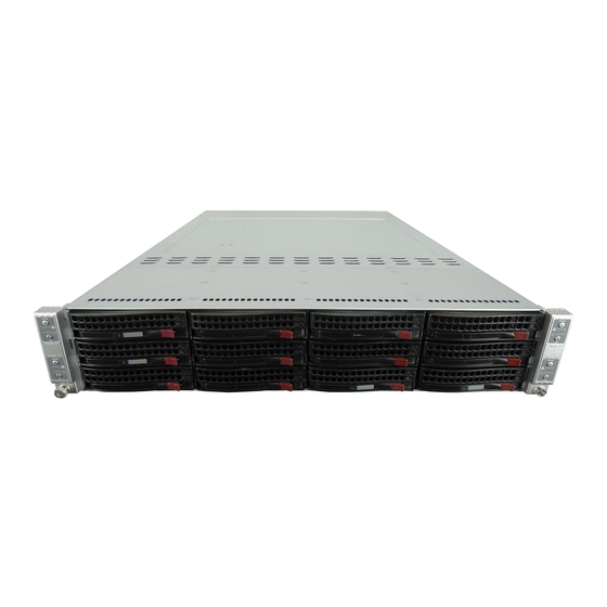
SUPERSERVER 6026TT-HT(R)F/HIBX(R)F/HIBQ(R)F USER'S MANUAL Figure 6-1. Chassis Front View Node B Control Panel Node D Control Panel Node A Control Panel SATA Drives (12) Node C Control Panel Figure 6-2. Chassis Rear View LAN Ports PCI-Express x16 Slot Power Supply** Dedicated IPMI LAN Port USB Ports VGA Port... -
Page 83: Fan Confi Guration
Chapter 6: Advanced Chassis Setup Fan Confi guration In the 2U Twin , each node (serverboard) controls the two fans that reside on its side of the chassis. This means that two nodes will share control for two fans. If the fan speed settings in BIOS are different for these two nodes, the BIOS setting with the higher fan speed will apply. -
Page 84: Hard Drive Installation/Removal
SUPERSERVER 6026TT-HT(R)F/HIBX(R)F/HIBQ(R)F USER'S MANUAL Hard Drive Installation/Removal Overview The hard drives are mounted in drive carriers to simplify their installation and removal from the chassis. These carriers also help promote proper airfl ow for the system. For this reason, even empty carriers without drives installed must remain in the chassis. - Page 85 Chapter 6: Advanced Chassis Setup Mounting a Hard Drive in a Carrier 1. Install the drive into the carrier with the printed circuit board side facing down so that the mounting holes align with those in the carrier. 2. Secure the drive to the carrier with six screws, as shown in Figure 6-4. 3.
- Page 86 2. Swing the handle fully out and use it to pull the unit straight out (see Figure 6-5). Figure 6-5. Removing a Hard Drive Warning: Enterprise level hard disk drives are recommended for use in Supermicro chassis and servers. For information on recommended HDDs, visit the Supermicro Web site at http://www.supermicro.com/products/nfo/fi les/ storage/SAS-CompList.pdf...
-
Page 87: Node Installation/Removal
Chapter 6: Advanced Chassis Setup Node Installation/Removal As with any server system, power must be removed from the serverboard when upgrading or installing memory or processors. In the 2U Twin server, the serverboards (nodes) are capable of being hot-swapped from the chassis, allowing one to be powered down for servicing while the others continue operating. - Page 88 SUPERSERVER 6026TT-HT(R)F/HIBX(R)F/HIBQ(R)F USER'S MANUAL Figure 6-7. Removing a System Node...
-
Page 89: Installing The Air Shrouds
Power Supply Failure: Single Power Supply Module If the power supply module fails, the system will shut down and you will need to replace the module. Replacements can be ordered directly from Supermicro (see contact information in the Preface). As there is only one power supply module in the system, power must be completely removed from the server before removing and replacing the power supply for whatever reason. -
Page 90: Power Supply Failure: Redundant Power (Two Modules)
LED on the control panel will fl ash slowly (about 4 seconds on and 4 off) and remain fl ashing until the failed unit has been replaced. Replacement units can be ordered directly from Supermicro (see contact information in the Preface). The power supply units have a hot-swap capability, meaning you can replace the failed unit without powering down the system. - Page 91 Chapter 6: Advanced Chassis Setup Figure 6-8. Removing the Power Supply Release Tab 6-11...
- Page 92 SUPERSERVER 6026TT-HT(R)F/HIBX(R)F/HIBQ(R)F USER'S MANUAL Notes 6-12...
-
Page 93: Chapter 7 Bios
When an option is selected in the left frame, it is highlighted in white. Often a text message will accompany it. (Note: the AMI BIOS has default text messages built in. Supermicro retains the option to include, omit, or change any of these text messages.) The AMI BIOS Setup Utility uses a key-based navigation system called "hot keys". -
Page 94: Starting The Setup Utility
Flashing the wrong BIOS can cause irreparable damage to the system. In no event shall Supermicro be liable for direct, indirect, special, incidental, or consequential damages arising from a BIOS update. If you have to update the BIOS, do not shut down or reset the system while the BIOS is updating. - Page 95 Day MM/DD/YY format. The time is entered in HH:MM:SS format. (Note: The time is in the 24-hour format. For example, 5:30 P.M. appears as 17:30:00.) Supermicro X8DTT/-F/-IBX/-IBXF/-IBQ/-IBQF BIOS Build Version This item displays the BIOS revision used in your system.
-
Page 96: Advanced Setup Confi Gurations
SUPERSERVER 6026TT-HT(R)F/HIBX(R)F/HIBQ(R)F USER'S MANUAL System Memory This displays the size of memory available in the system: Size This item displays the memory size detected by the BIOS. Advanced Setup Confi gurations Use the arrow keys to select Boot Setup and hit <Enter> to access the submenu items: BOOT Features Quick Boot... - Page 97 Chapter 7: BIOS Bootup Num-Lock This feature selects the Power-on state for Numlock key. The options are Off and On. Wait For 'F1' If Error This forces the system to wait until the 'F1' key is pressed if an error occurs. The options are Disabled and Enabled.
-
Page 98: Processor And Clock Options
SUPERSERVER 6026TT-HT(R)F/HIBX(R)F/HIBQ(R)F USER'S MANUAL Processor and Clock Options This submenu allows the user to confi gure the Processor and Clock settings. Ratio CMOS Setting This option allows the user to set the ratio between the CPU Core Clock and the FSB Frequency. - Page 99 Chapter 7: BIOS Simultaneous Multi-Threading (Available when supported by the CPU) Set to Enabled to use the Simultaneous Multi-Threading Technology, which will result in increased CPU performance. The options are Disabled and Enabled. Active Processor Cores Set to Enabled to use a processor's Second Core and beyond. (Please refer to Intel's web site for more information.) The options are All, 1 and 2.
-
Page 100: Advanced Chipset Control
SUPERSERVER 6026TT-HT(R)F/HIBX(R)F/HIBQ(R)F USER'S MANUAL Advanced Chipset Control The items included in the Advanced Settings submenu are listed below: CPU Bridge Confi guration QPI Links Speed This feature selects QPI's data transfer speed. The options are Slow-mode, and Full Speed. QPI Frequency This selects the desired QPI frequency. - Page 101 Chapter 7: BIOS Patrol Scrubbing A memory error-correction scheme that works in the background looking for and correcting resident errors. The options are Enabled and Disabled. NUMA Support Select Enabled to use the feature of Non-Uniform Memory Access to improve CPU performance.
- Page 102 SUPERSERVER 6026TT-HT(R)F/HIBX(R)F/HIBQ(R)F USER'S MANUAL Altitude This feature defi nes how many meters above or below sea level the system is located. The options are Sea Level or Below, 1~300, 301~600, 601~900, 901~1200, 1201~1500, 1501~1800, 1801~2100, 2101~2400, 2401~2700, 2701~3000. DIMM Pitch This is the physical space between each DIMM module.
- Page 103 Chapter 7: BIOS SouthBridge Confi guration This feature allows the user to confi gure the settings for the Intel ICH South Bridge chipset. USB Functions This feature allows the user to decide the number of onboard USB ports to be enabled.
- Page 104 SUPERSERVER 6026TT-HT(R)F/HIBX(R)F/HIBQ(R)F USER'S MANUAL IDE/SATA Confi guration When this submenu is selected, the AMI BIOS automatically detects the presence of the IDE devices and displays the following items: SATA#1 Confi guration If Compatible is selected, it sets SATA#1 to legacy compatibility mode, while selecting Enhanced sets SATA#1 to native SATA mode.
- Page 105 Chapter 7: BIOS Type Select the type of device connected to the system. The options are Not Installed, Auto, CD/DVD and ARMD. LBA/Large Mode LBA (Logical Block Addressing) is a method of addressing data on a disk drive. In the LBA mode, the maximum drive capacity is 137 GB. For drive capacities over 137 GB, your system must be equipped with a 48-bit LBA mode addressing.
- Page 106 SUPERSERVER 6026TT-HT(R)F/HIBX(R)F/HIBQ(R)F USER'S MANUAL DMA Mode Select Auto to allow the BIOS to automatically detect IDE DMA mode when the IDE disk drive support cannot be determined. Select SWDMA0 to allow the BIOS to use Single Word DMA mode 0. It has a data transfer rate of 2.1 MB/s.
- Page 107 Chapter 7: BIOS 32Bit Data Transfer Select Enable to enable the function of 32-bit IDE data transfer. The options are Enabled and Disabled. IDE Detect Timeout (sec) Use this feature to set the time-out value for the BIOS to detect the ATA, ATAPI devices installed in the system.
- Page 108 SUPERSERVER 6026TT-HT(R)F/HIBX(R)F/HIBQ(R)F USER'S MANUAL Super IO Device Confi guration Serial Port1 Address/ Serial Port2 Address This option specifi es the base I/O port address and the Interrupt Request address of Serial Port 1 and Serial Port 2. Select Disabled to prevent the serial port from accessing any system resources.
-
Page 109: Hardware Health Monitor
Chapter 7: BIOS VT-UTF8 Combo Key Support A terminal keyboard defi nition that provides a way to send commands from a remote console. The options are Enabled and Disabled. Sredir Memory Display Delay This feature defi nes the length of time in seconds to display memory information. The options are No Delay, Delay 1 Sec, Delay 2 Sec, and Delay 4 Sec. - Page 110 ‘Temperature Tolerance’ is, and not the other way around. This results in better CPU thermal management. Supermicro has leveraged this feature by assigning a temperature status to certain thermal conditions in the processor (Low, Medium and High). This makes it easier for the user to understand the CPU’s temperature status, rather than by just simply...
- Page 111 Chapter 7: BIOS System Temperature: The system temperature will be displayed (in degrees in Celsius and Fahrenheit) as it is detected by the BIOS. Fan Speed Control Monitor This feature allows the user to decide how the system controls the speeds of the onboard fans.
- Page 112 SUPERSERVER 6026TT-HT(R)F/HIBX(R)F/HIBQ(R)F USER'S MANUAL High Performance Event Timer Select Enabled to activate the High Performance Event Timer (HPET) that produces periodic interrupts at a much higher frequency than a Real-time Clock (RTC) does in synchronizing multimedia streams, providing smooth playback and reducing the dependency on other timestamp calculation devices, such as an x86 RDTSC Instruction embedded in the CPU.
-
Page 113: View Bmc System Event Log
Chapter 7: BIOS View BMC System Event Log This feature displays the BMC System Event Log (SEL). It shows the total number of entries of BMC System Events. To view an event, select an Entry Number and pressing <Enter> to display the information as shown in the screen. •... - Page 114 SUPERSERVER 6026TT-HT(R)F/HIBX(R)F/HIBQ(R)F USER'S MANUAL IP Address Source Select the source of this machine's IP address. If Static is selected, you will need to know and enter manually the IP address of this machine below. If DHCP is selected, the BIOS will search for a DHCP (Dynamic Host Confi guration Protocol) server in the network it is attached to, and request the next available IP address.
-
Page 115: Dmi Event Log
Chapter 7: BIOS Subnet Mask This item displays the current subnet mask setting for your IPMI connection. Current Subnet Mask in BMC This item displays the current subnet mask used for your IPMI connection. Gateway Address Confi guration Enter the gateway address for this machine. This should be in decimal and in dotted quad form (i.e., 192.168.10.253). -
Page 116: Security Settings
SUPERSERVER 6026TT-HT(R)F/HIBX(R)F/HIBQ(R)F USER'S MANUAL Security Settings The AMI BIOS provides a Supervisor and a User password. If you use both passwords, the Supervisor password must be set fi rst. Supervisor Password This item indicates if a Supervisor password has been entered for the system. "Not Installed"... -
Page 117: Boot Confi Guration
Chapter 7: BIOS Clear User Password (Available only when User Password has been set) This item allows you to clear a user password after it has been entered. Password Check This item allows you to check a password after it has been entered. The options are Setup and Always. -
Page 118: Hard Disk Drives
SUPERSERVER 6026TT-HT(R)F/HIBX(R)F/HIBQ(R)F USER'S MANUAL Hard Disk Drives This feature allows the user to specify the boot sequence from all available hard disk drives. The settings are Disabled and a list of all hard disk drives that have been detected (i.e., 1st Drive, 2nd Drive, 3rd Drive, etc). •... - Page 119 Chapter 7: BIOS Save Changes and Exit When you have completed the system confi guration changes, select this option to leave the BIOS Setup Utility and reboot the computer, so the new system confi guration parameters can take effect. Select Save Changes and Exit from the Exit menu and press <Enter>.
-
Page 120: Bios Recovery
Flashing the wrong BIOS can cause irreparable damage to the system. In no event shall Supermicro be liable for direct, indirect, special, incidental, or consequential damages arising from a BIOS update. If you need to update the BIOS, do not shut down or reset the system while the BIOS is updating. -
Page 121: Boot Sector Recovery From An Ide Cd-Rom
Chapter 7: BIOS Boot Sector Recovery from an IDE CD-ROM This process is almost identical to the process of Boot Sector Recovery from a USB device, except that the BIOS image fi le is loaded from a CD-ROM. Use a CD-R or CD-RW drive to burn a CD with the BIOS image fi... - Page 122 SUPERSERVER 6026TT-HT(R)F/HIBX(R)F/HIBQ(R)F USER'S MANUAL 4. Power on your system and click the <Connect> button in the Hyper Terminal. The terminal screen will display the following messages. Press <SpaceBar> to update BIOS. Confirm update BIOS? (y/n) y Begin remote BIOS flash? (y/n) y Starting remote flash.
- Page 123 Chapter 7: BIOS c. Press <Send> to start ROM File extraction. (See the picture below.) d. Once the ROM fi le extraction is completed, the message: "New BIOS received OK" will display. 8. Once remote BIOS fl ash is completed, the system will reboot. Note: AMIBIOS Serial Flash will work with any terminal communications program that supports VT-100 and XModem protocols, including protocols designed for GNU/LINUX &...
- Page 124 SUPERSERVER 6026TT-HT(R)F/HIBX(R)F/HIBQ(R)F USER'S MANUAL Notes 7-32...
-
Page 125: Appendix A Bios Error Beep Codes
Appendix A: BIOS Error Beep Codes Appendix A BIOS Error Beep Codes During the POST (Power-On Self-Test) routines, which are performed each time the system is powered on, errors may occur. Non-fatal errors are those which, in most cases, allow the system to continue the boot-up process. - Page 126 SUPERSERVER 6026TT-HT(R)F/HIBX(R)F/HIBQ(R)F USER'S MANUAL Notes...
-
Page 127: Appendix B System Specifi Cations
Appendix C: System Specifi cations Appendix B System Specifi cations Note: unless noted specifi cations apply to a complete system (four serverboards). Processors Eight Intel® 5500/5600 series processors in LGA 1366 sockets Note: Please refer to our website for details on supported processors. Chipset Intel 5520/ICH10R BIOS... - Page 128 Rated Output Power: 1400W (Part# PWS-1K41P-1R) 80 Plus Gold Certifi ed Rated Output Voltages: +12V (91A @ 110V, 116A @ 180~240V), +5Vsb (4A @ 240V, 4A @ 100V) Note: The SuperServer 6026TT-HTRF, 6026TT-HIBXRF and 6026TT-HIBQRF servers all come with a redundant power supply. Operating Environment Operating Temperature: 10º...
- Page 129 Appendix C: System Specifi cations Regulatory Compliance Electromagnetic Emissions: FCC Class A, EN 55022 Class A, EN 61000-3-2/-3- 3, CISPR 22 Class A Electromagnetic Immunity: EN 55024/CISPR 24, (EN 61000-4-2, EN 61000-4-3, EN 61000-4-4, EN 61000-4-5, EN 61000-4-6, EN 61000-4-8, EN 61000-4-11) Safety: CSA/EN/IEC/UL 60950-1 Compliant, UL or CSA Listed (USA and Canada), CE Marking (Europe) California Best Management Practices Regulations for Perchlorate Materials:...
- Page 130 Notes (continued from front) The products sold by Supermicro are not intended for and will not be used in life support systems, medical equipment, nuclear facilities or systems, aircraft, aircraft devices, aircraft/emergency com- munication devices or other critical systems whose failure to perform be reasonably expected to result in signifi...
Need help?
Do you have a question about the SuperServer 6026TT-HTRF and is the answer not in the manual?
Questions and answers