Table of Contents
Advertisement
Quick Links
Advertisement
Table of Contents

Related Manuals for Supermicro SuperStorageSystem 6048R-E1CR45H


Summary of Contents for Supermicro SuperStorageSystem 6048R-E1CR45H
- Page 1 SuperStorageSystem 6048R-E1CR45H 6048R-E1CR45L USER’S MANUAL Revision 1.0a...
- Page 2 This product, including software and docu- mentation, is the property of Supermicro and/or its licensors, and is supplied only under a license. Any use or reproduction of this product is not allowed, except as expressly permitted by the terms of said license.
- Page 3 Preface Preface About This Manual This manual is written for professional system integrators and PC technicians. It provides information for the installation and use of the SSG-6048R-E1CR45H/L. Installation and maintenance should be performed by experienced technicians only. The SSG-6048R-E1CR45H/L. is a high-end storage system based on the SC946LTS-R1K66P 4U rackmount chassis and the X10DSC+ dual processor serverboard.
- Page 4 SuperStorageSystem SSG-6048R-E1CR45H/L User's Manual Chapter 5: Advanced Serverboard Setup Chapter 5 provides detailed information on the X10DSC+ serverboard, including the locations and functions of connections, headers and jumpers. Refer to this chapter when adding or removing processors or main memory and when reconfiguring the serverboard.
- Page 5 Preface Notes...
-
Page 6: Table Of Contents
Server Chassis Features ................1-3 System Power ....................1-3 Hard Drives ..................... 1-3 Front Control Panel ..................1-3 Cooling System ....................1-3 Contacting Supermicro ..................1-5 Chapter 2 Server Installation Overview ......................2-1 Unpacking the System ..................2-1 Preparing for Setup ..................2-1 Choosing a Setup Location ................ - Page 7 Table of Contents Optional Quick Installation Method ............... 2-10 Accessing Top-Loading Hard Drives .............2-11 Adapters for Round and Threaded Hole Racks ..........2-11 Chapter 3 System Interface Overview ......................3-1 Control Panel Buttons ..................3-2 Control Panel LEDs ..................3-2 Drive Carrier LEDs ..................3-4 SAS3/SATA3 Drives ..................
- Page 8 SuperStorageSystem SSG-6048R-E1CR45H/L User's Manual Backplane Voltage ..................4-13 Comply with Local and National Electrical Codes ........4-14 Product Disposal ................... 4-15 Hot Swap Fan Warning ................. 4-16 Power Cable and AC Adapter ..............4-18 Chapter 5 Advanced Serverboard Setup Handling the Serverboard ................5-1 Precautions .....................
- Page 9 Table of Contents Installing Hard Drives Into Carriers ..............6-8 Installing Hard Drive Carriers into the Storage Chassis ......... 6-9 Installing Optional Rear 2.5" Hot-Swappable Drives ........6-9 Installing Hard Drives Into the Rear Carriers ..........6-9 Installing Hot-Swappable Optional NVMe Drives ......... 6-12 Installing the NVMe Drive Cage..............
- Page 10 SuperStorageSystem SSG-6048R-E1CR45H/L User's Manual Notes...
-
Page 11: Chapter 1 Introduction
One set of mounting rails (MCP-290-00150-0N) Note: For your system to work properly, please follow the links below to download all necessary drivers/utilities and the user’s manual for your server. • Supermicro product manuals: http://www.supermicro.com/support/manuals/ • Product drivers and utilities: ftp://ftp.supermicro.com... -
Page 12: Serverboard Features
The X10DSC+ supports single or dual Intel® Xeon E5-2600 (v3/v4) Series pro- cessors. Please refer to the serverboard description pages on our website for a complete listing of supported processors (www.supermicro.com). Memory The X10DSC+ has twenty-four (24) DIMM slots that can support up to 1.5 TB of Load Reduced (LRDIMM) or 768 GB of Registered (RDIMM) ECC... -
Page 13: Pci Expansion Slots
Chapter 1: Introduction PCI Expansion Slots The X10DSC+ has two (2) PCI-E 3.0 x16 and one (1) PCI-E 3.0 x8 (the PCI-E 3.0 x8 slot is used for an add-on card). Rear I/O Ports The I/O ports include one COM port, a VGA port, two USB 3.0 ports and a dedicated IPMI LAN (Ethernet) port. - Page 14 SuperStorageSystem SSG-6048R-E1CR45H/L User's Manual Figure 1-1. Intel C612 Chipset: System Block Diagram Note: This is a general block diagram. Please see Chapter 5 for details. X10DSC+ Block Diagram NCSI DDR3 DDR3 NCSI AST2400 IPMI LAN RTL8211E 32MB BMC UART COM1 SPI Flash SPI USB 16MB BMC...
-
Page 15: Contacting Supermicro
Super Micro Computer, Inc. 980 Rock Ave. San Jose, CA 95131 U.S.A. Tel: +1 (408) 503-8000 Fax: +1 (408) 503-8008 Email: marketing@supermicro.com (General Information) support@supermicro.com (Technical Support) Website: www.supermicro.com Europe Address: Super Micro Computer B.V. Het Sterrenbeeld 28, 5215 ML... - Page 16 SuperStorageSystem SSG-6048R-E1CR45H/L User's Manual Notes...
-
Page 17: Chapter 2 Server Installation
Chapter 2: Server Installation Chapter 2 Server Installation Overview This chapter provides a quick setup checklist to get the SSG-6048R-E1CR45H/L up and running. Following these steps in the order given should enable you to have the system operational within a minimum amount of time. This quick setup assumes that your system has come to you with the processors and memory preinstalled. -
Page 18: Warnings And Precautions
SuperStorageSystem SSG-6048R-E1CR45H/L User's Manual • This product is for installation only in a Restricted Access Location (dedicated equipment rooms, service closets and the like). • This product is not suitable for use with visual display work place devices ac- cording to §2 of the German Ordinance for Work with Visual Display Units. Warnings and Precautions Rack Precautions •... -
Page 19: Rack Mounting Considerations
Chapter 2: Server Installation Rack Mounting Considerations Ambient Operating Temperature If installed in a closed or multi-unit rack assembly, the ambient operating temperature of the rack environment may be greater than the room's ambient temperature. Therefore, consideration should be given to installing the equipment in an environment compatible with the manufacturer’s maximum rated ambient temperature (Tmra). -
Page 20: Rack Mounting Instructions
SuperStorageSystem SSG-6048R-E1CR45H/L User's Manual Rack Mounting Instructions This section provides information on installing the chassis into a rack unit with the rails provided. There are a variety of rack units on the market, which may mean that the assembly procedure will differ slightly from the instructions provided. You should also refer to the installation instructions that came with the rack unit you are using. -
Page 21: Releasing The Inner Rail
Chapter 2: Server Installation Releasing the Inner Rail Releasing Inner Rail from the Outer Rails 1. Identify the left and right outer rail assemblies as described on page 5-4. 2. Pull the inner rail out of the outer rail until it is fully extended as illustrated below. - Page 22 SuperStorageSystem SSG-6048R-E1CR45H/L User's Manual Inner Rails Figure 2-3. Installing the Inner Rails...
-
Page 23: Installing The Inner Rails On The Storage Chassis
Chapter 2: Server Installation Installing The Inner Rails on the Storage Chassis Installing the Inner Rails 1. Confirm that the left and right inner rails have been correctly identified. Place the inner rail firmly against the side of the storage chassis, aligning the hooks on the side of the storage chassis with the holes in the inner rail. -
Page 24: Installing The Outer Rails On The Rack
SuperStorageSystem SSG-6048R-E1CR45H/L User's Manual Installing the Outer Rails on the Rack Installing the Outer Rails 1. Press upward on the locking tab at the rear end of the middle rail. 2. Push the middle rail back into the outer rail. 3. -
Page 25: Installing To The Rack
Chapter 2: Server Installation Installing to the Rack Installing the Chassis into a Rack 1. Confirm that the inner rails are properly installed on the chassis and the outer rails are correctly installed on the rack. 2. Pull the middle rail out from the front of the outer rail and make sure that the ball-bearing shuttle is at the front locking position of the middle rail. -
Page 26: Optional Quick Installation Method
SuperStorageSystem SSG-6048R-E1CR45H/L User's Manual 6. Depress the locking tabs of both sides at the same time and push the storage chassis all the way into the rear of the rack. 7. If necessary for security purposes, use screws to secure the storage chassis handles to the front of the rack. -
Page 27: Accessing Top-Loading Hard Drives
Chapter 2: Server Installation Accessing Top-Loading Hard Drives After completing the rack installation steps on the previous pages, the top-loading functionality of your chassis can be utilized while mounted in a rack system without removing the chassis from the rack. Accessing the Storage Chassis in a Rack 1. -
Page 28: Chapter 3 System Interface
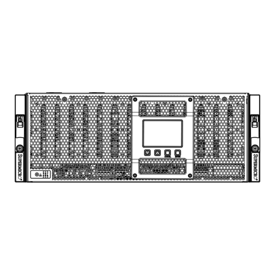
Chapter 3: System Interface Chapter 3 System Interface Overview The storage chassis features a large, easy-to-read LCD screen with screen naviga- tion buttons. This LCD screen displays information about the system. The control panel is located on the front edge of the storage chassis and features system status LEDs, a power on/off button and reset button. -
Page 29: Control Panel Buttons
SuperStorageSystem SSG-6048R-E1CR45H/L User's Manual Control Panel Buttons There are two push-buttons located on the left handle of the chassis. These are (in order from left to right) a power on/off button and a reset button. Power: The main power button is used to apply or remove power from the power supply to the server system. - Page 30 Chapter 3: System Interface NIC1: Indicates network activity on GLAN1 when flashing. NIC2: Indicates network activity on GLAN2 when flashing. Information LED: Alerts operator of several states, as noted in the table below. Information LED Status Description An overheat condition has occurred. Continuously on and red (This may be caused by cable congestion.) Blinking red (1Hz)
-
Page 31: Drive Carrier Leds
SuperStorageSystem SSG-6048R-E1CR45H/L User's Manual Drive Carrier LEDs The SC946LTS chassis supports SAS3 or SATA3 drives. SAS3/SATA3 Drives Each SAS3/SATA3 drive carrier has two LEDs. • Blue: Solid on = Drive is present and available. Blinking = Drive is actively being accessed. Each SATA drive carrier has a blue LED. -
Page 32: System Status Lcd Screen
Chapter 3: System Interface System Status LCD Screen The SSG-6048R-E1CR45H/L offers an optional LCD screen on the front of the chassis that shows the status of many system components. The functions are described in this section. Introduction This feature gives the user the ability to monitor drives, power supplies, fans, and connections. -
Page 33: Main Screen
SuperStorageSystem SSG-6048R-E1CR45H/L User's Manual Main Screen After a welcome page, the Main screen appears. UID Alert Error Alert Throughout the GUI, component status is displayed in color where green indicates normal operation, red indicates a problem, and gray indicates the component is not installed. -
Page 34: Processor Status
Chapter 3: System Interface Processor Status Main Page > System Status > Processor This page displays CPU information including model (SKU), temperature and status. The status may be operational (good, green), failed (bad, red), or not installed (gray). Memory Status Main Page >... -
Page 35: Ipmi Submenu
SuperStorageSystem SSG-6048R-E1CR45H/L User's Manual IPMI Submenu Main Page > IPMI System Info Main Page > IPMI > System Info The IPMI System Info pages show: • LCD firmware version • IPMI firmware version • BMC IP Address • MAC Address •... -
Page 36: Ipmi Event Log
Chapter 3: System Interface IPMI Event Log Main Page > IPMI > Event Log Event Log page will show the latest 100 critical errors: • /*CPU OverHeating*/ • /*MEM OverHeating*/ • /*PSU FAIL*/ • /*MEM ECC Error*/ • /*MEM MRC Error*/ •... -
Page 37: Uid Message
SuperStorageSystem SSG-6048R-E1CR45H/L User's Manual UID Message A message pops up whenever the user activates UID. The UID icon (blue circle with a white exclamation mark) in the bottom right corner remains active until the user turns off UID. 3-10... -
Page 38: Chapter 4Standardized Warning Statements For Ac Systems
The following statements are industry standard warnings, provided to warn the user of situations which have the potential for bodily injury. Should you have questions or experience difficulty, contact Supermicro's Technical Support department for assistance. Only certified technicians should attempt to install or configure components. - Page 39 SuperStorageSystem SSG-6048R-E1CR45H/L User's Manual Warnung WICHTIGE SICHERHEITSHINWEISE Dieses Warnsymbol bedeutet Gefahr. Sie befinden sich in einer Situation, die zu Verletzungen führen kann. Machen Sie sich vor der Arbeit mit Geräten mit den Gefahren elektrischer Schaltungen und den üblichen Verfahren zur Vorbeugung vor Unfällen vertraut.
- Page 40 Chapter 4: Warning Statements for AC Systems . ٌ ا ك ً ف حالة و ٌ يك أى تتسبب ف اصابة جسذ ة ٌ هذا الزهز ع ٌ خطز !تحذ ز قبل أى تعول عىل أي هعذات،يك عىل علن بالوخاطز ال ا ٌجوة عي الذوائز ٍ...
-
Page 41: Installation Instructions
SuperStorageSystem SSG-6048R-E1CR45H/L User's Manual Installation Instructions Warning! Read the installation instructions before connecting the system to the power source. 設置手順書 システムを電源に接続する前に、 設置手順書をお読み下さい。 警告 将此系统连接电源前,请先阅读安装说明。 警告 將系統與電源連接前,請先閱讀安裝說明。 Warnung Vor dem Anschließen des Systems an die Stromquelle die Installationsanweisungen lesen. ¡Advertencia! Lea las instrucciones de instalación antes de conectar el sistema a la red de alimentación. -
Page 42: Circuit Breaker
Chapter 4: Warning Statements for AC Systems Circuit Breaker Warning! This product relies on the building's installation for short-circuit (overcurrent) protection. Ensure that the protective device is rated not greater than: 250 V, 20 A. サーキッ ト ・ ブレーカー この製品は、 短絡 (過電流) 保護装置がある建物での設置を前提としています。 保護装置の定格が250 V、... -
Page 43: Power Disconnection Warning
SuperStorageSystem SSG-6048R-E1CR45H/L User's Manual هذا املنتج يعتمد عىل معداث الحاميت مه الدوائ ر القصرية التي تم تثبيتها يف املبنى 20A, 250V : تأكد من أن تقييم الجهاز الوقايئ ليس أكرث من 경고! 이 제품은 전원의 단락(과전류)방지에 대해서 전적으로 건물의 관련 설비에 의존합니다. - Page 44 Chapter 4: Warning Statements for AC Systems ¡Advertencia! El sistema debe ser disconnected de todas las fuentes de energía y del cable eléctrico quitado de los módulos de fuente de alimentación antes de tener acceso el interior del chasis para instalar o para quitar componentes de sistema. Attention Le système doit être débranché...
-
Page 45: Equipment Installation
SuperStorageSystem SSG-6048R-E1CR45H/L User's Manual Equipment Installation Warning! Only trained and qualified personnel should be allowed to install, replace, or service this equipment. 機器の設置 トレーニングを受け認定された人だけがこの装置の設置、 交換、 またはサービスを許可 されています。 警告 只有经过培训且具有资格的人员才能进行此设备的安装、更换和维修。 警告 只有經過受訓且具資格人員才可安裝、更換與維修此設備。 Warnung Das Installieren, Ersetzen oder Bedienen dieser Ausrüstung sollte nur geschultem, qualifiziertem Personal gestattet werden. -
Page 46: Restricted Area
Chapter 4: Warning Statements for AC Systems Waarschuwing Deze apparatuur mag alleen worden geïnstalleerd, vervangen of hersteld door geschoold en gekwalificeerd personeel. Restricted Area Warning! This unit is intended for installation in restricted access areas. A restricted access area can be accessed only through the use of a special tool, lock and key, or other means of security. -
Page 47: Battery Handling
SuperStorageSystem SSG-6048R-E1CR45H/L User's Manual אזור עם גישה מוגבלת !אזהרה יש להתקין את היחידה באזורים שיש בהם הגבלת גישה. הגישה ניתנת בעזרת (.'כלי אבטחה בלבד (מפתח, מנעול וכד . تخصيص هذه انىحذة نترك ب ُها ف مناطق محظورة تم ، م َ كن انىصىل إن منطقت محظورة فقط من خالل استخذاو أداة خاصت أو... - Page 48 Chapter 4: Warning Statements for AC Systems Warnung Bei Einsetzen einer falschen Batterie besteht Explosionsgefahr. Ersetzen Sie die Batterie nur durch den gleichen oder vom Hersteller empfohlenen Batterietyp. Entsorgen Sie die benutzten Batterien nach den Anweisungen des Herstellers. Attention Danger d'explosion si la pile n'est pas remplacée correctement. Ne la remplacer que par une pile de type semblable ou équivalent, recommandée par le fabricant.
-
Page 49: Redundant Power Supplies
SuperStorageSystem SSG-6048R-E1CR45H/L User's Manual Redundant Power Supplies Warning! This unit might have more than one power supply connection. All connections must be removed to de-energize the unit. 冗長電源装置 このユニッ トは複数の電源装置が接続されている場合があります。 ユニッ トの電源を切るためには、 すべての接続を取り外さなければなりません。 警告 此部件连接的电源可能不止一个,必须将所有电源断开才能停止给该部件供电。 警告 此裝置連接的電源可能不只一個,必須切斷所有電源才能停止對該裝置的供電。 Warnung Dieses Gerät kann mehr als eine Stromzufuhr haben. Um sicherzustellen, dass der Einheit kein trom zugeführt wird, müssen alle Verbindungen entfernt werden. -
Page 50: Backplane Voltage
Chapter 4: Warning Statements for AC Systems . قد يكون لهذا الجهاز عدة اتصاالت بوحدات امداد الطاقة يجب إ ز الة كافة االتصاالت لعسل الوحدة عن الكهرباء 경고! 이 장치에는 한 개 이상의 전원 공급 단자가 연결되어 있을 수 있습니다. 이 장치에 전원을... -
Page 51: Comply With Local And National Electrical Codes
SuperStorageSystem SSG-6048R-E1CR45H/L User's Manual מתח בפנל האחורי !אזהרה קיימת סכנת מתח בפנל האחורי בזמן תפעול המערכת. יש להיזהר במהלך .העבודה هناك خطز مه التيار الكهزبايئ أوالطاقة املىجىدة عىل اللىحة عندما يكىن النظام يعمل كه حذ ر ا عند خدمة هذا الجهاس 경고! 시스템이... -
Page 52: Product Disposal
Chapter 4: Warning Statements for AC Systems Attention L'équipement doit être installé conformément aux normes électriques nationales et locales. תיאום חוקי החשמל הארצי !אזהרה .התקנת הציוד חייבת להיות תואמת לחוקי החשמל המקומיים והארציים تركيب املعدات الكهربائية يجب أن ميتثل للقىاويه املحلية والىطىية املتعلقة بالكهرباء... -
Page 53: Hot Swap Fan Warning
SuperStorageSystem SSG-6048R-E1CR45H/L User's Manual Attention La mise au rebut ou le recyclage de ce produit sont généralement soumis à des lois et/ou directives de respect de l'environnement. Renseignez-vous auprès de l'organisme compétent. סילוק המוצר !אזהרה .סילוק סופי של מוצר זה חייב להיות בהתאם להנחיות וחוקי המדינה التخلص... - Page 54 Chapter 4: Warning Statements for AC Systems Warnung Gefährlich Bewegende Teile. Von den bewegenden Lüfterblätter fern halten. Die Lüfter drehen sich u. U. noch, wenn die Lüfterbaugruppe aus dem Chassis genommen wird. Halten Sie Finger, Schraubendreher und andere Gegenstände von den Öffnungen des Lüftergehäuses entfernt. ¡Advertencia! Riesgo de piezas móviles.
-
Page 55: Power Cable And Ac Adapter
Electrical Appliance and Material Safety Law prohibits the use of UL or CSA -certified cables (that have UL/CSA shown on the code) for any other electrical devices than products designated by Supermicro only.. 電源コードとACアダプター 製品を設置する場合、 提供または指定および購入された接続ケーブル、 電源コードとAC アダプターを... - Page 56 -בכבלים המוסמכים בUL -או בCSA (( כאשר מופיע עליהם קוד שלUL/CSA עבור כל מוצר חשמלי אחר, אלא רק במוצר אשר הותאם ע"יSupermicro .בלבד عند تركيب املنتج، قم باستخدام التوصيالت املتوفرة أو املحددة أو قم ب رش اء الكابالت الكهربائية ومحوالت التيار...
- Page 57 Het gebruik van niet geschikte Kabels en/of Adapters kan een storing of brand veroorzaken. Wetgeving voor Elektrische apparatuur en Materiaalveiligheid verbied het gebruik van UL of CSA -gecertificeerde Kabels (met UL/CSA in de code) voor elke andere toepassing dan de door Supermicro hiervoor beoogde Producten. 4-20...
-
Page 58: Chapter 5 Advanced Serverboard Setup
Chapter 5: Advanced Serverboard Setup Chapter 5 Advanced Serverboard Setup This chapter covers the steps required to connect the data and power cables and install add-on cards. All serverboard jumpers and connections are also described. A layout and quick reference chart are included in this chapter for your reference. Remember to completely close the chassis when you have finished working with the serverboard to better cool and protect the system. -
Page 59: Connecting Data Cables
SuperStorageSystem SSG-6048R-E1CR45H/L User's Manual Several cables need to be connected to the serverboard. These include the data cables for the peripherals and control panel and the power cables. Connecting Data Cables The cables used to transfer data from the peripheral devices have been carefully routed to prevent them from blocking the flow of cooling air that moves through the system from front to back. -
Page 60: Rear I/O Ports
Chapter 5: Advanced Serverboard Setup Figure 5-1. Control Panel Header Pins Ground Power Button Ground Reset Button Power Fail LED 3.3V OH/Fan Fail/ UID LED PWR Fail LED) NIC2 Activity LED NIC2 Link LED NIC1 Activity LED NIC1 Link LED UID Switch HDD LED FP PWRLED... -
Page 61: Installing The Processor And Heatsink
CPU socket cap is in place and none of the socket pins are bent; otherwise, contact your retailer immediately. • Refer to the Supermicro web site for updates on CPU support. Installing an LGA2011 Processor 1. There are two levers on the... - Page 62 Chapter 5: Advanced Serverboard Setup 3. With the lever labeled 'Close 1st' fully retracted, gently push down on the 'Open 1st' lever to open the load plate. Lift the load plate to open it completely. Gently push 4. Using your thumb and the index down to pop finger, remove the 'WARNING' the load plate...
- Page 63 SuperStorageSystem SSG-6048R-E1CR45H/L User's Manual Warning: You can only install the CPU to the socket in one direction. Make sure that the CPU is properly inserted into the socket before closing the load plate. If it doesn't close properly, do not force it as it may damage your CPU. Instead, open the load plate again and double-check that the CPU is aligned properly.
-
Page 64: Installing A Passive Cpu Heatsink
Chapter 5: Advanced Serverboard Setup Installing a Passive CPU Heatsink 1. Do not apply any thermal grease to the heatsink or the CPU die. The required amount has already been applied. 2. Place the heatsink on top of the CPU so that the four mounting holes are aligned with those on the serverboard and the heatsink bracket underneath. -
Page 65: Installing Memory
SuperStorageSystem SSG-6048R-E1CR45H/L User's Manual Installing Memory Caution: Exercise extreme care when installing or removing DIMM modules to prevent any possible damage. Memory Support The X10DSC+ supports up to 1.5 TB of Load Reduced (LRDIMM) or 768 GB of Registered (RDIMM) ECC DDR4-2400/2133/1866/1600 memory. For best performance, install pairs of memory modules of the same type and speed. - Page 66 Chapter 5: Advanced Serverboard Setup Processor & Memory Module Population Configuration Follow the tables below for correct memory installation. Processors and their Corresponding Memory Modules CPU# Corresponding DIMM Modules CPU 1 CPU2 Processor and Memory Module Population for Optimal Performance Number of CPU and Memory Population Configuration Table CPUs+DIMMs...
-
Page 67: Serverboard Details
SuperStorageSystem SSG-6048R-E1CR45H/L User's Manual Serverboard Details Figure 5-5. X10DSC+ Layout COM1 USB0/1(3.0) LED1 IPMI_LAN CPU2_MEMORY_LED CPU1_MEMORY_LED BMC_HB_LED1 CPU1 SIOM PCI-E 3.0 CPU2 HDD_LED1 LED2 CPU1 JSD2 JSD1 JBAT1 BIOS Battery S-SGPIO1 X10DSC+ REV:1.01 JITP1 JPW2 BIOS JPW3 IPMI CODE CPU-XDP LICENSE JPW1 BAR CODE... - Page 68 Chapter 5: Advanced Serverboard Setup X10DSC+ Quick Reference Jumper Description Default Setting JBT1 Clear CMOS/Reset BIOS Configuration See Section 5-8 JPB1 BMC Enable Pins 1-2 (Enabled) JPG1 VGA Enable Pins 1-2 (Enabled) JPME2 Manufacture (ME) Mode Select Pins 1-2 (Normal) JWD1 Watch Dog Timer Enable Pins 1-2 (Reset)
-
Page 69: Connector Definitions
SuperStorageSystem SSG-6048R-E1CR45H/L User's Manual X10DSC+ Quick Reference (cont.) Description State Status LED_A1-A3 CPU1 Memory Fail LED for DIMMs A1-A3 Memory Failure LED_B1-B3 CPU1 Memory Fail LED for DIMMs B1-B3 Memory Failure LED_C1-C3 CPU1 Memory Fail LED for DIMMs C1-C3 Memory Failure LED_D1-D3 CPU1 Memory Fail LED for DIMMs D1-D3 Memory Failure... - Page 70 Chapter 5: Advanced Serverboard Setup Power Button Power Button Pin Definitions (JF1) The Power On connection is on pins Pin# Definition 1 and 2 of JF1. These should be Power Signal connected to the chassis power button. Ground Momentarily contacting both pins will power on/off the system.
- Page 71 SuperStorageSystem SSG-6048R-E1CR45H/L User's Manual NIC2 (JLAN2) LED NIC2 LED Pin Definitions (JF1) The LED connections for LAN2 are on Pin# Definition pins 9 and 10 of JF1. Attach an LED Activity cable to display network activity. See Link the table on the right for pin definitions. NIC1 (JLAN1) LED NIC1 LED Pin Definitions (JF1)
- Page 72 Chapter 5: Advanced Serverboard Setup Fan Headers Fan Header Pin Definitions (FAN1-8) There are five fan headers on the Pin# Definition serverboard, all of which are 4-pin Ground (Black) fans. Pins 1-3 of the fan headers +12V (Red) are backward compatible with the traditional 3-pin fans.
- Page 73 SuperStorageSystem SSG-6048R-E1CR45H/L User's Manual SGPIO Headers SGPIO Header Pin Definitions An SGPIO (Serial General Purpose Pin# Definition Definition Input/Output) header is used to communicate with the enclosure Ground DATA Out management chip on the backplane. SGPIO1 supports the I-SATA0-3 Load Ground ports.
- Page 74 Chapter 5: Advanced Serverboard Setup Universal Serial Bus (USB) USB 0/1 and Type A (USB 2) Pin Definitions Two USB 3.0 ports (USB 0/1) are Pin# Description located on the rear I/O panel. In VBUS addition, a Type A connector (USB SSRX- 2) is provided to support front access (cables not included).
- Page 75 Note: UID can also be triggered via IPMI. For more information on IPMI, please refer to the IPMI User's Guide posted on our website at http://www.supermicro.com. TPM Header/Port 80 TPM/Port 80 Header...
-
Page 76: Jumper Settings
Chapter 5: Advanced Serverboard Setup Jumper Settings Explanation of Jumpers To modify the operation of the Connector Pins serverboard, jumpers can be used to choose between optional settings. Jumpers create shorts between two Jumper pins to change the function of the connector. - Page 77 SuperStorageSystem SSG-6048R-E1CR45H/L User's Manual Watch Dog Enable/Disable Watch Dog Jumper Settings Jumper JWD controls the Watch Dog Jumper Setting Definition function. Watch Dog is a system Pins 1-2 Reset monitor that can reboot the system Pins 2-3 when a software application hangs. Jumping pins 1-2 will cause WD to Open Disabled...
-
Page 78: Onboard Indicators
Chapter 5: Advanced Serverboard Setup Onboard Indicators Dedicated IPMI LAN LEDs IPMI LAN Link LED (Left) & Activity LED (Right) A dedicated IPMI LAN is also located Color/State Definition on the I/O back panel. The amber LED Link (Left) Green: Solid 100 Mbps on the right indicates activity, while the Amber: Solid... -
Page 79: 5-10 Sas/Sata Ports
The 6048R-E1CR45L has an LSI 3008 controller card included in the system to support SATA 3.0/SAS 3.0 hard drives. (RAID 0, 1, and 10 supported). Note: For more information on SATA HostRAID configuration, please refer to the Intel SATA HostRAID User's Guide posted on our website at http://www.supermicro. com.. 5-22... -
Page 80: 5-11 Installing Software
Chapter 5: Advanced Serverboard Setup 5-11 Installing Software The Supermicro FTP site contains drivers and utilities for your system at ftp://ftp. supermicro.com. Some of these must be installed, such as the chipset driver. After accessing the FTP site, go into the CDR_Images directory and locate the ISO file for your serverboard. -
Page 81: Superdoctor® 5
SuperStorageSystem SSG-6048R-E1CR45H/L User's Manual SuperDoctor® 5 The Supermicro SuperDoctor 5 is a program that functions in a command-line or web-based interface in Windows and Linux operating systems. The program monitors system health information such as CPU temperature, system voltages, system power consumption, fan speed, and provides alerts via email or Simple Network Management Protocol (SNMP). -
Page 82: 5-12 Onboard Battery
Chapter 5: Advanced Serverboard Setup 5-12 Onboard Battery Care must be taken to assure that the chassis cover is in place when the system is operating to assure proper cooling. Out of warranty damage to the system can occur if this practice is not strictly followed. Figure 5-8. -
Page 83: Chapter 6 Advanced Chassis Setup
Chapter 6: Advanced Chassis Setup Chapter 6 Advanced Chassis Setup This chapter covers the steps required to install components and perform mainte- nance on the SC946LTS-R1K66P chassis. For component installation, follow the steps in the order given to eliminate the most common problems encountered. If some steps are unnecessary, skip ahead to the step that follows. -
Page 84: Control Panel
SuperStorageSystem SSG-6048R-E1CR45H/L User's Manual LCD Screen Control Panel 2.5" Drives (2) Power Supplies (2) Network (LAN) Ports I/O Ports Expansion Card Slots Figure 6-1. Front and Rear Chassis Views Control Panel The control panel (located on the front of the chassis) must be connected to the JF1 connector on the serverboard to provide you with system status indications. -
Page 85: Opening And Closing The Chassis Cover
Chapter 6: Advanced Chassis Setup Opening and Closing the Chassis Cover Thumb Screw Thumb Screw Figure 6-2. Removing the Chassis Cover Opening the Chassis Cover 1. Power down the system and disconnect the AC power cords from the power supplies. 2. -
Page 86: System Fans
SuperStorageSystem SSG-6048R-E1CR45H/L User's Manual System Fans Five heavy-duty, hot-swappable fans provide cooling for the system. The SC946LTS features three fans that can be removed individually and two that are paired in a dual fan module. The fans an be removed without powering down the system. Individual fans Three cooling fans are mounted individually on the lower left of the rear of the stor- age chassis when facing the rear of the storage chassis. -
Page 87: Dual Rear Fan Module
Chapter 6: Advanced Chassis Setup Dual Rear Fan Module The SC946LTS chassis supports two rear-mounted cooling fans in a hot-swappable dual fan unit. Release Tabs Release Tabs Figure 6-5. Dual Fan Module Replacing a System Fan 1. While the power is running, examine the fans to determine which fan has failed. -
Page 88: Installing The Hdd Support Partitions
SuperStorageSystem SSG-6048R-E1CR45H/L User's Manual Installing the HDD Support Partitions Figure 6-7. Installing the Hard Drive Support Partitions Prior to installing top-loading 3.5" hard drives into the SC946LTS chassis, it is necessary to install the two hard drive support partitions included with the system. Installing the HDD Support Partitions 1. -
Page 89: Installing Hot-Swappable 3.5" Hard Drives
Chapter 6: Advanced Chassis Setup Installing Hot-Swappable 3.5" Hard Drives Drive Carrier Handle Release Button Figure 6-8. Removing a 3.5" Hard Drive Carrier The SC946LTS chassis supports forty-five (45) 3.5" hard drives in toolless hard drive carriers to simplify their removal from the chassis. These carriers also help promote proper airflow through the storage chassis. -
Page 90: Installing Hard Drives Into Carriers
Notch for Connectors Figure 6-9. Installing a 3.5" Hard Drive into a Hard Drive Carrier Warning: Enterprise level hard disk drives are recommended for use in Supermicro storage chassis and servers. For information on recommended HDDs, visit the Supermicro website at www.supermicro.com. -
Page 91: Installing Hard Drive Carriers Into The Storage Chassis
Chapter 6: Advanced Chassis Setup Installing Hard Drive Carriers into the Storage Chassis Installing 3.5" Hard Drives and Carriers into the Storage Chassis 1. Grasp the hard drive carrier handle. 2. Push the hard drive carrier into the hard drive bay until it clicks into the locked position. - Page 92 SuperStorageSystem SSG-6048R-E1CR45H/L User's Manual Dummy Drive Hard Drive Carrier Figure 6-11. Removing the Dummy Drive From the Carrier Installing 2.5" Hard Drives Into Carriers 1. Remove the four screws securing the dummy drive to the hard drive carrier and set them aside for later use. 2.
- Page 93 Chapter 6: Advanced Chassis Setup installing Rear Hard Drive Carriers 1. Using the drive carrier handle, push the hard drive and carrier into the rear bay of the storage chassis. 2. Push the drive carrier into the drive bay until it clicks into the locked position. Figure 6-13.
-
Page 94: Installing Hot-Swappable Optional Nvme Drives
SuperStorageSystem SSG-6048R-E1CR45H/L User's Manual Installing Hot-Swappable Optional NVMe Drives Figure 6-14. Installing the NVMe Drive Cage The SC946LTS storage chassis supports the option for six 2.5" hot-swappable NVMe drives in tool less hard drive carriers, which are mounted in a fixed NVMe drive cage. -
Page 95: Installing Nvme Drive Carriers Into The Nvme Drive Cage
2. Grasp the drive carrier handle and pull the carrier up and out of the NVMe cage. Warning: Enterprise level hard disk drives are recommended for use in Supermicro storage chassis and servers. For information on recommended HDDs, visit the Supermicro website at www.supermicro.com. -
Page 96: Accessing The Motherboard For Memory Upgrades And Maintenance
SuperStorageSystem SSG-6048R-E1CR45H/L User's Manual Accessing the Motherboard for Memory Upgrades and Maintenance The following access method allows the motherboard to be accessed for memory upgrades and other maintenance without removing the motherboard tray from the chassis. Figure 6-16. Accessing Expansion Card Slots Through the Dual Fan Bay Accessing the Motherboard 1. -
Page 97: Expansion Card Setup
Chapter 6: Advanced Chassis Setup Expansion Card Setup The X10DSC+ motherboard has three PCI slots available to populate with expan- sion cards.. Expansion Card Slots Figure 6-17. PCI Card Slot (Shown with MB removed during initial setup) PCI Slot Setup for Expansion Cards Installing Expansion Cards 1. -
Page 98: Installing The Siom Network Module
SuperStorageSystem SSG-6048R-E1CR45H/L User's Manual Installing the SIOM Network Module Figure 6-18. Installing the SIOM Network Module (Shown with MB removed during initial setup) The SC946LTS storage chassis supports a Super In/Out Module (SIOM) which provides additional ports for expanded network capability. Installing the SIOM Network Module 1. -
Page 99: Installing Heatsinks
Chapter 6: Advanced Chassis Setup Installing Heatsinks Figure 6-19. Installing Heatsinks (Shown with MB removed during initial setup) Installing Heatsinks 1. Power down the system and disconnect the AC power cords from power sup- plies. 2. Pull the motherboard tray out only two inches and access the motherboard as described at the beginning of this section. -
Page 100: 6-10 Ipmi Connector
SuperStorageSystem SSG-6048R-E1CR45H/L User's Manual 6-10 IPMI Connector To access the IPMI connector it is necessary to remove the center fan. It is not necessary to power down the system. Accessing the IPMI Connector 1. While the power is running, remove the center hot-swappable fan as illus- trated below and described Section 6-4 in the Individual Fans section. -
Page 101: 6-11 Accessing The Backplane And Power Card
Chapter 6: Advanced Chassis Setup 6-11 Accessing the Backplane and Power Card The backplane and power card are stored in a backplane tray, which is accessible through the top of the storage chassis. The following actions are to be performed by authorized personnel only. -
Page 102: 6-12 Installing The Cable Management Arm
SuperStorageSystem SSG-6048R-E1CR45H/L User's Manual Installing the Backplane 1. Place the backplane in the chassis and tighten the screw to secure it to the storage chassis. 2. Tighten the five screws securing the HDD brackets. 3. Place the HDD support partitions in the chassis and secure them with the four screws previously set aside. - Page 103 Chapter 6: Advanced Chassis Setup Figure 6-23. Installing Connectors 1 and 2 3. Slide CMA connector #3 forward onto the two posts on the rear of the left middle rail. It snaps into place. 4. For CMA connector #4, align the metal tabs with the slots on the rear of the left outer rail and push it forward.
- Page 104 SuperStorageSystem SSG-6048R-E1CR45H/L User's Manual Figure 6-25. Routing the Cables 5. Open the four red plastic caps and route the cables into the wire carrier. 6. If necessary, adjust the U-brackets to clear chassis components. Figure 6-26. Adjusting the U-Brackets 6-22...
- Page 105 Chapter 6: Advanced Chassis Setup 7. Use the six Velcro straps to secure the cables to the CMA. Use a strap on either side of each joint and one on each U-bracket, inserting it through the slot on the bracket. 8.
-
Page 106: 6-13 Power Supply
An illuminated green light indicates that the power supply is operating. Redundant power supplies are hot-swappable and can be changed without powering down the system. New units can be ordered directly from Supermicro (see contact information in the Preface). -
Page 107: Chapter 7 Bios
When an option is selected in the left frame, it is highlighted in white. Often a text message will accompany it. Note: the AMI BIOS has default text messages built in. Supermicro retains the option to include, omit, or change any of these text messages. -
Page 108: How To Start The Setup Utility
Flashing the wrong BIOS can cause irreparable damage to the system. In no event shall Supermicro be liable for direct, indirect, special, incidental, or consequential damages arising from a BIOS update. If you have to update the BIOS, do not shut down or reset the system while the BIOS is updating to avoid possible boot failure. - Page 109 MM/DD/YYYY format. The time is entered in HH:MM:SS format. Note: The time is in the 24-hour format. For example, 5:30 P.M. appears as 17:30:00. Supermicro X10DSC+ BIOS Version: This item displays the version of the BIOS ROM used in the system.
-
Page 110: Advanced Setup Configurations
SuperStorageSystem SSG-6048R-E1CR45H/L User's Manual Advanced Setup Configurations Use the arrow keys to select Advanced setup and press <Enter> to access the submenu items: Warning: Take Caution when changing the Advanced settings. An incorrect value, a very high DRAM frequency or an incorrect BIOS timing setting may cause the system to malfunction. - Page 111 Chapter 7: BIOS Wait For 'F1' If Error Select Enabled to force the system to wait until the <F1> key is pressed when an error occurs. The options are Disabled and Enabled. INT19 Trap Response Interrupt 19 is the software interrupt that handles the boot disk function. When this item is set to Immediate, the ROM BIOS of the host adaptors will "capture"...
- Page 112 SuperStorageSystem SSG-6048R-E1CR45H/L User's Manual CPU Configuration This submenu displays the following CPU information as detected by the BIOS. It also allows the user to configure CPU settings. • Processor Socket • Processor ID • Processor Frequency • Processor Max Ratio •...
- Page 113 Chapter 7: BIOS illegal codes to overwhelm the processor to damage the system during an attack. The options are Enable and Disable. (Refer to Intel's and Microsoft's websites for more information.) PPIN Control Select Unlock/Enable to use the Protected-Processor Inventory Number (PPIN) control in the system.
- Page 114 SuperStorageSystem SSG-6048R-E1CR45H/L User's Manual AES-NI Select Enable to use the Intel Advanced Encryption Standard (AES) New Instruc- tions (NI) to ensure data security. The options are Enable and Disable. Intel Virtualization Technology Select Enable to use Intel Virtualization Technology for Direct I/O VT-d support by reporting the I/O device assignments to the VMM (Virtual Machine Monitor) through the DMAR ACPI tables.
- Page 115 Chapter 7: BIOS *If the option is set to Custom, the following items will display: CPU P State Control (Available when Power Technology is set to Custom) EIST (P-states) EIST (Enhanced Intel SpeedStep Technology) allows the system to automatically adjust processor voltage and core frequency to reduce power consumption and heat dissipation.
- Page 116 SuperStorageSystem SSG-6048R-E1CR45H/L User's Manual Enhanced Halt State (C1E) Select Enable to use the "Enhanced Halt State" feature, which will significantly reduce the CPU's power consumption by reducing CPU's clock cycle and voltage during a "Halt State." The options are Disable and Enable. ...
- Page 117 Chapter 7: BIOS IOU0 (IIO1 PCIe Port 2) This item configures the PCI-E port Bifuraction setting for a PCI-E port specified by the user. The options are x4x4x4x4, x4x4x8, x8x4x4, x8x8, x16, and Auto. IIO1 Port 2A Link Speed This item configures the link speed of a PCI-E port specified by the user. The options are Gen 1 (Generation 1) (2.5 GT/s), Gen 2 (Generation 2) (5 GT/s), and Gen 3 (Generation 3) (8 GT/s).
- Page 118 SuperStorageSystem SSG-6048R-E1CR45H/L User's Manual IOU1 (IIO2 PCIe Port 3) This item configures the PCI-E port Bifuraction setting for a PCI-E port specified by the user. The options are x4x4x4x4, x4x4x8, x8x4x4, x8x8, x16, and Auto. IIO2 Port 3A Link Speed This item configures the link speed of a PCI-E port specified by the user.
- Page 119 Chapter 7: BIOS QPI (Quick Path Interconnect) Configuration QPI General Configuration QPI Status The following information will display: • Number of CPU • Number of II0 • Current QPI Link Speed • Current QPI Link Frequency • QPI Global MMIO Low Base/Limit •...
- Page 120 SuperStorageSystem SSG-6048R-E1CR45H/L User's Manual Isoc Mode Select Enable for Isochronous support to meet QoS (Quality of Service) require- ments. This feature is especially important for Intel's Virtualization Technology. The options are Enable and Disable. Memory Configuration This submenu allows the user to configure Integrated Memory Controller (IMC) settings.
- Page 121 Chapter 7: BIOS Memory RAS (Reliability_Availability_Serviceability) Configuration Use this submenu to configure the following Memory RAS settings. RAS Mode When Independent is selected, all memory modules operate independently. When Mirror is selected, the motherboard maintains two identical copies of all data in memory for data backup.
- Page 122 SuperStorageSystem SSG-6048R-E1CR45H/L User's Manual South Bridge Configuration The following South Bridge information will display: USB Configuration • USB Module Version • USB Controllers • USB Devices Legacy USB Support Select Enabled to support onboard legacy USB devices. Select Auto to disable legacy support when there are no legacy USB devices present.
- Page 123 Chapter 7: BIOS EHCI2 Select Enabled to enable EHCI (Enhanced Host Controller Interface) support on USB 2.0 connector #2 (-at least one USB 2.0 connector should be enabled for EHCI support.) The options are Disabled and Enabled. XHCI Pre-Boot Driver Select Enabled to load Intel XHCI pre-boot driver.
- Page 124 SuperStorageSystem SSG-6048R-E1CR45H/L User's Manual sSATA Port 0 ~ Port 3 Hot Plug Select Enabled to enable hot-plugging support for a port specified by the user, which will allow the user to replace a sSATA disk drive installed on this port without shutting down the system.
- Page 125 Chapter 7: BIOS note that the option-Both is not supported by the Windows Server 2012/R2 OS. The options are Both, SATA Controller, and sSATA Controller. sSATA Port 0 ~ Port 3 Hot Plug Select Enabled to enable hot-plugging support for a port specified by the user, which will allow the user to replace a sSATA disk drive installed on this port without shutting down the system.
- Page 126 SuperStorageSystem SSG-6048R-E1CR45H/L User's Manual • PCI Devices Common Settings PCI PERR/SERR Support Select Enabled to support PERR (PCI/PCI-E Parity Error)/SERR (System Error) runtime error reporting for a PCI/PCI-E slot. The options are Enabled and Disabled. Above 4G Decoding (Available if the system supports 64-bit PCI decoding) Select Enabled to decode a PCI device that supports 64-bit in the space above 4G Address.
- Page 127 Chapter 7: BIOS PCI Devices Option ROM Settings CPU2 PCI-E 3.0x8 Slot1 OPROM/CPU2 PCI-E 3.0x16 Slot2 OPROM/CPU2 PCI-E 3.0x16 Slot3 OPROM/CPU1 SAS AOM1 (Add-On Module#1) Slot4 OPROM/CPU1 SIOM Card Slot5 OPROM Select Enabled to enable Option ROM support to boot the computer using a de- vice installed on the slot specified by the user.
- Page 128 SuperStorageSystem SSG-6048R-E1CR45H/L User's Manual Device Settings This item displays the base I/O port address and the Interrupt Request address for a serial port specified by the user. The default setting for Serial Port 1 is IO=3F8h IRQ=4. Change Port 1 Settings This feature specifies the base I/O port address and the Interrupt Request address of Serial Port 1.
- Page 129 Chapter 7: BIOS Parity A parity bit can be sent along with regular data bits to detect data transmission errors. Select Even if the parity bit is set to 0, and the number of 1's in data bits is even. Select Odd if the parity bit is set to 0, and the number of 1's in data bits is odd.
- Page 130 SuperStorageSystem SSG-6048R-E1CR45H/L User's Manual Redirection After BIOS Post Use this item to enable or disable legacy Console Redirection after BIOS POST (Power-On Self-Test). When "Bootloader" is selected, legacy Console Redirec- tion is disabled before booting the OS. When "Always Enable" is selected, legacy Console Redirection remains enabled while the OS boots up.
- Page 131 Chapter 7: BIOS the data bits. Select Space to add a Space as a parity bit to be sent with your data bits. The options are None, Even, Odd, Mark and Space. Stop Bits A stop bit indicates the end of a serial data packet. Select 1 Stop Bit for standard serial data communication.
- Page 132 SuperStorageSystem SSG-6048R-E1CR45H/L User's Manual Serial Port for Out-of-Band Management/Windows Emergency Management Services (EMS) The submenu allows the user to configure Console Redirection settings to support Out-of-Band Serial Port management. (EMS) Console Redirection Select Enabled to use a COM port selected by the user for EMS Console Redirec- tion.
- Page 133 Chapter 7: BIOS the receiving buffer is empty. The options are None, Hardware RTS/CTS, and Software Xon/Xoff. The following settings will be displayed: Data Bits, Parity, Stop Bits Enabling TPM in the BIOS The steps below describe the proper procedure on how to enable the TPM in the BIOS.
- Page 134 EV DFX (Device Function On-Hide) support for the system to work properly. (EV DFX is under "IIO Configuration" in the "Chipset/North Bridge" submenu on Page 4-10). For more information on TPM, please refer to the TPM manual at http://www.supermicro.com/manuals/other/ AOM-TPM-9655V_9655H.pdf ACPI Settings ...
- Page 135 Chapter 7: BIOS iSCSI Configuration This item displays iSCSI configuration information: iSCSI Initiator Name Use this item to enter the name of the iSCSI Initiator, which is a unique name used in the world. The name must in the IQN format. The following submenu will be available for configuration: ...
-
Page 136: Event Logs
SuperStorageSystem SSG-6048R-E1CR45H/L User's Manual Event Logs This submenu allows the user to configure Event Log settings. Change SMBIOS Event Log Settings This feature allows the user to configure SMBIOS Event settings. Enabling/Disabling Options SMBIOS Event Log Select Enabled to enable SMBIOS (System Management BIOS) Event Logging during system boot. - Page 137 Chapter 7: BIOS SMBIOS Event Log Standard Settings Log System Boot Event Select Enabled to log system boot events. The options are Disabled and Enabled. MECI (Multiple Event Count Increment) Enter the increment value for the multiple event counter. Enter a number between 1 to 255.
-
Page 138: Ipmi
SuperStorageSystem SSG-6048R-E1CR45H/L User's Manual IPMI This submenu allows the user to configure IPMI settings. The following items will be displayed: • BMC (Baseboard Management Controller) Firmware Revision • IPMI Status System Event Log Enabling/Disabling Options SEL Components Select Enabled to enable all system event logging support at bootup. The options are Enabled and Disabled. - Page 139 Chapter 7: BIOS When SEL is Full This feature allows the user to determine what the AMI BIOS should do when the system event log is full. Select Erase Immediately to erase all events in the log when the system event log is full. The options are Do Nothing and Erase Immediately. Note: After making changes on a setting, be sure to reboot the system for the changes to take effect.
-
Page 140: Security Settings
SuperStorageSystem SSG-6048R-E1CR45H/L User's Manual VLAN Select Enabled to enable onboard LAN connections to be used for Intel Virtualization Technology. The options are Enable and Disable. Security Settings This submenu allows the user to configure the following security settings for the system. - Page 141 Chapter 7: BIOS Secure Boot Menu The following items will display: • System Mode • Secure Boot • Vendor Keys Secure Boot Select Enable for secure boot support to ensure system security at bootup. The options are Enabled and Disabled. Secure Boot Mode This item allows the user to select the desired secure boot mode for the system.
-
Page 142: Boot Settings
SuperStorageSystem SSG-6048R-E1CR45H/L User's Manual Key Exchange Key This feature allows the user to configure and save Key-Exchange-Key settings. Authorized Signatures This feature allows the user to set and save authorized signatures and grant access to those whose names appear on the list. Forbidden Signatures ... - Page 143 Chapter 7: BIOS Boot Configuration Setup Prompt Timeout Use this item to enter the number of seconds for the system to wait for the setup activation key before entering the Setup utility. Enter 65535 (0xFFFF) to wait indefinitely. Boot Mode Select Use this item to select the type of device to be used for system boot.
-
Page 144: Save & Exit
SuperStorageSystem SSG-6048R-E1CR45H/L User's Manual Delete Boot Option Use this item to select a boot device to delete from the boot priority list. Delete Boot Option Select the target boot device to delete from the boot priority list. Hard Disk Drive BBS Priorities •... - Page 145 Chapter 7: BIOS Discard Changes and Exit Select this item to exit from the BIOS setup without making any permanent changes to the system configuration, and reboot the computer. Save Changes and Reset When you have completed the system configuration changes, select this item to leave the BIOS setup utility and reboot the computer for the new system configura- tion parameters to take effect.
- Page 146 SuperStorageSystem SSG-6048R-E1CR45H/L User's Manual Notes 7-40...
-
Page 147: Appendix A Bios Error Beep Codes
Appendix A: BIOS POST Error Codes Appendix A BIOS Error Beep Codes During the POST (Power-On Self-Test) routines, which are performed at each system boot, errors may occur. Non-fatal errors are those which, in most cases, allow the system to continue to boot. - Page 148 SuperStorageSystem SSG-6048R-E1CR45H/L User's Manual Notes...
-
Page 149: Appendix B System Specifications
Appendix B: System Specifications Appendix B System Specifications Processors Single or dual Intel Xeon E5-2600 (V3/V4) Series processors Note: Please refer to our web site for a complete listing of supported processors. Chipset Intel C612 chipset BIOS 16 Mb AMI® SPI Flash ROM Memory Capacity Twenty-four (24) DIMM sockets supporting up to 1.5 TB of Load Reduced (LRDIMM) or 768 GB of Registered (RDIMM) ECC DDR4-2400/2133/1866/1600... - Page 150 SuperStorageSystem SSG-6048R-E1CR45H/L User's Manual Weight Gross: 225 lbs (102 kg) System Cooling Up to five (5) 8-cm system fans Power Supply Rated Output Power: 2000 Watt (Part# PWS-2K05A-1R) Rated Output Voltages: 100-127V: +12V (83A), +12Vsb (2.1A), 200-240V: +12V (167A), +12Vsb (2.1A) System Input Requirements AC Input Voltage: 100 - 240V AC auto-range Rated Input Current: 110V: 12 - 8A, 1280W output @ 180-240V: 8 - 6A...
- Page 151 Appendix B: System Specifications Notes...
- Page 152 SuperStorageSystem SSG-6048R-E1CR45H/L User's Manual (continued from front) The products sold by Supermicro are not intended for and will not be used in life support systems, medical equipment, nuclear facilities or systems, aircraft, aircraft devices, aircraft/emergency com- munication devices or other critical systems whose failure to perform be reasonably expected to result in significant injury or loss of life or catastrophic property damage.
Need help?
Do you have a question about the SuperStorageSystem 6048R-E1CR45H and is the answer not in the manual?
Questions and answers