Table of Contents
Advertisement
Quick Links
Advertisement
Chapters
Table of Contents

Related Manuals for HEIDENHAIN 548431-05


Summary of Contents for HEIDENHAIN 548431-05
- Page 1 MANUALplus 620 User’s Manual NC Software 548431-05 English (en) 12/2017...
- Page 3 Overview of keys...
- Page 4 Confirm the entry DINplus – Unit mode ISO Mode Enter Simulation Select tool data and technology data: Tool editor Technology editor Select Organization operating mode: Machine parameters Transfer Project management Network connection Diagnostics HEIDENHAIN | MANUALplus 620 | User's Manual | 12/2017...
- Page 5 Open the error window Error Start the integrated calculator Calculator Show additional information in the parameter editor Call the TURNguide Information Select alternative input Activate the alphabetic keyboard Go to Print Screen DIADUR HEIDENHAIN | MANUALplus 620 | User's Manual | 12/2017...
- Page 6 Overview of keys Operating panel of the control MC 7410T MC 8420T HEIDENHAIN | MANUALplus 620 | User's Manual | 12/2017...
- Page 7 Fundamentals...
- Page 8 Signal word indicating the hazard severity Type and source of hazard Consequences of ignoring the hazard, e.g.: "There is danger of collision during subsequent machining operations" Escape – Hazard prevention measures HEIDENHAIN | MANUALplus 620 | User's Manual | 12/2017...
- Page 9 Would you like to see any changes made, or have you found any errors? We are continuously striving to improve our documentation for you. Please help us by sending your requests to the following e-mail address: tnc-userdoc@heidenhain.de HEIDENHAIN | MANUALplus 620 | User's Manual | 12/2017...
- Page 10 HEIDENHAIN also offers the DataPilot MP 620 or DataPilot CP 640 software for PCs, which is designed for use with the respective control. The DataPilot is suitable for both shop-floor programming as well as off-location program creation and testing.
- Page 11 The spindle synchronization option G720 synchronizes the shaft speeds of two or more spindles so that they rotate synchronously with a gear ratio or a defined offset, see the smart.Turn and DIN Programming User's Manual HEIDENHAIN | MANUALplus 620 | User's Manual | 12/2017...
- Page 12 DIN Programming User's Manual With G924, a Fluctuating speed can be programmed to prevent resonance, see the smart.Turn and DIN Programming User's Manual HEIDENHAIN | MANUALplus 620 | User's Manual | 12/2017...
- Page 13 DIN Programming User's Manual Recesses that were defined with G22 can be machined with the new Cycle G870 ICP Recessing, see the smart.Turn and DIN Programming User's Manual HEIDENHAIN | MANUALplus 620 | User's Manual | 12/2017...
- Page 14 The parameter Y was added to G720, see the smart.Turn and DIN Programming User's Manual The parameters O and U were added to G860, see the smart.Turn and DIN Programming User's Manual HEIDENHAIN | MANUALplus 620 | User's Manual | 12/2017...
- Page 15 Parameters ensuring maximum compatibility with the ICP contour description were added to G0, G1, G12/G13, G101, G102/G103, G110, G111, G112/G113, G170, G171, G172/G173, G180, G181, and G182/G183, see the smart.Turn and DIN Programming User's Manual HEIDENHAIN | MANUALplus 620 | User's Manual | 12/2017...
- Page 16 Skip levels can be defined in the smart.Turn operating mode, see the smart.Turn and DIN Programming User's Manual A function was introduced to output information on the tool status, see the smart.Turn and DIN Programming User's Manual HEIDENHAIN | MANUALplus 620 | User's Manual | 12/2017...
- Page 17 For systems with a C axis, the position display in the machine data display (axis letter and index) can be configured by the machine manufacturer The functions G0, G1, and G701 have been enhanced with parameters for auxiliary axes HEIDENHAIN | MANUALplus 620 | User's Manual | 12/2017...
- Page 18 DIN Programming User's Manual Machining parameters are displayed in millimeters or inches according to the CfgUnitOfMeasure parameter (101100) HEIDENHAIN | MANUALplus 620 | User's Manual | 12/2017...
- Page 19 "Diagnostic bits", Page 570 In Tool editor operating mode, the Max. shaft speed NMX tool parameter was added, see "General tool parameters", Page 576 HEIDENHAIN | MANUALplus 620 | User's Manual | 12/2017...
- Page 20 5 lines on 19" screens, see "Machine data display", Page 102 On 19” screens, the Transfer machine soft key is located in the first soft-key row, see the smart.Turn and DIN Programming User's Manual HEIDENHAIN | MANUALplus 620 | User's Manual | 12/2017...
- Page 21 The input range of the Overlap factor U cycle parameter was extended to 0.99 for milling cycles. In order to avoid unwanted data loss, the default setting for Parameter restore was set to Pocket table HEIDENHAIN | MANUALplus 620 | User's Manual | 12/2017...
- Page 22 HEIDENHAIN | |...
-
Page 23: Table Of Contents
Operating the Touchscreen......................83 Machine mode of operation......................91 Teach-in............................171 ICP programming..........................415 Graphic simulation........................529 Tool and technology database....................557 Organization mode of operation....................603 10 Tables and overviews........................677 11 Overview of cycles........................711 HEIDENHAIN | MANUALplus 620 | User's Manual | 12/2017... - Page 24 Contents HEIDENHAIN | MANUALplus 620 | User's Manual | 12/2017...
- Page 25 Polar coordinates............................54 Machine datum............................54 Workpiece datum........................... 55 Units of measure........................... 55 Tool dimensions........................... 56 Tool length..............................56 Tool compensation..........................56 Tool-tip radius compensation (TRC)....................... 57 Milling cutter radius compensation (MCRC)..................57 HEIDENHAIN | MANUALplus 620 | User's Manual | 12/2017...
- Page 26 INTERNAL INFO soft key........................72 Clearing errors............................73 Error log..............................74 Keystroke log............................74 Saving service files..........................75 TURNguide context-sensitive help.....................76 Application.............................. 76 Working with the TURNguide........................77 Downloading current help files......................81 DataPilot programming station......................82 Application.............................. 82 Operation..............................82 HEIDENHAIN | MANUALplus 620 | User's Manual | 12/2017...
- Page 27 Overview of possible gestures......................85 Navigating in the table and NC programs..................... 86 Operating the Simulation........................87 Using the HEROS menu........................88 Functions in the taskbar........................89 Touchscreen Configuration........................89 Touchscreen Cleaning..........................89 HEIDENHAIN | MANUALplus 620 | User's Manual | 12/2017...
- Page 28 Calibrating the tool touch probe......................126 Displaying operating times........................127 Configuring the HR 550FS wireless handwheel.................. 128 Setting the system time........................131 Tool measurement..........................132 Touch-off............................... 133 Touch probe (tool touch probe)......................134 HEIDENHAIN | MANUALplus 620 | User's Manual | 12/2017...
- Page 29 Using load monitoring during production.....................162 4.11 Graphic simulation..........................163 4.12 Program management........................164 Program selection..........................164 File manager............................166 Project management..........................167 4.13 Conversion into DIN format......................168 Making a conversion..........................168 4.14 Units of measure..........................169 HEIDENHAIN | MANUALplus 620 | User's Manual | 12/2017...
- Page 30 Finishing cut transv.—Expanded......................213 Cutting, longitudinal plunge........................215 Cutting, transverse plunge........................217 Cutting, longitudinal plunge—Expanded....................219 Cutting, transverse plunge—Expanded....................221 Longitudinal cutting, finishing plunge....................223 Traverse cutting, finishing plunge......................225 Longitudinal cutting, finishing plunge—Expanded................227 HEIDENHAIN | MANUALplus 620 | User's Manual | 12/2017...
- Page 31 Taper thread............................321 API thread............................324 Recutting threads (longitudinally)......................326 Recutting threads, Expanded (longitudinally)..................328 Recutting taper threads........................330 Recutting API threads.......................... 332 Undercut DIN 76..........................334 Undercut DIN 509 E..........................336 HEIDENHAIN | MANUALplus 620 | User's Manual | 12/2017...
- Page 32 Linear milling pattern, radial.........................403 Circular drilling pattern, axial........................ 404 Circular drilling pattern, radial.......................406 Circular milling pattern, axial........................ 407 Circular milling pattern, radial.......................409 Examples of pattern machining......................410 5.10 DIN cycles............................413 DIN cycle..............................413 HEIDENHAIN | MANUALplus 620 | User's Manual | 12/2017...
- Page 33 Manipulating contour elements......................441 Zoom functions in ICP editor submode..................446 Changing the detail..........................446 Workpiece blank definition....................... 448 Workpiece blank – bar......................... 448 Workpiece blank – tube........................448 Workpiece blank – Cast part........................448 HEIDENHAIN | MANUALplus 620 | User's Manual | 12/2017...
- Page 34 6.14 Contours in the XY plane......................... 495 Reference data in XY plane......................... 495 Basic elements of XY plane.........................496 Form elements of XY plane.........................499 Figures, patterns and holes in XY plane (front face)................500 HEIDENHAIN | MANUALplus 620 | User's Manual | 12/2017...
- Page 35 Figures, patterns, and holes in YZ plane (lateral surface)..............516 6.16 Loading existing contours........................ 526 Integrating cycle contours in smart.Turn mode of operation...............526 DXF contours (option).......................... 527 6.17 Contour groups..........................528 Contour groups in smart.Turn mode of operation................528 HEIDENHAIN | MANUALplus 620 | User's Manual | 12/2017...
- Page 36 Saving the contour..........................549 Saving the generated contour in Simulation submode................549 Dimensioning............................550 Measuring the generated contour in Simulation submode..............550 Settings............................... 552 General Settings...........................552 7.10 3-D simulation............................ 554 3-D simulation in Simulation submode....................554 HEIDENHAIN | MANUALplus 620 | User's Manual | 12/2017...
- Page 37 Burr cutters............................592 Knurling tool............................593 Touch probes............................594 Stopper tools............................595 Gripper..............................596 Technology database......................... 597 Technology editor submode......................... 598 Editing a workpiece-material or cutting-material list................599 Displaying and editing cutting data......................600 HEIDENHAIN | MANUALplus 620 | User's Manual | 12/2017...
- Page 38 Transferring tool data........................... 664 Creating service files........................... 666 Creating a data backup file........................668 Importing NC programs from predecessor controls................669 Importing tool data from the CNC PILOT 4290...................674 Service pack............................675 Installing a service pack........................676 HEIDENHAIN | MANUALplus 620 | User's Manual | 12/2017...
- Page 39 DIN 76 – undercut parameters......................685 DIN 509 E – undercut parameters......................686 DIN 509 F – undercut parameters......................686 10.3 Technical information.........................687 10.4 Compatibility in DIN programs......................696 10.5 Syntax elements provided by the control..................699 HEIDENHAIN | MANUALplus 620 | User's Manual | 12/2017...
- Page 40 11 Overview of cycles........................711 11.1 Workpiece blank cycles and single cut cycles................712 11.2 Turning cycles............................. 713 11.3 Recessing and recess-turning cycles....................714 11.4 Thread cycles............................715 11.5 Drilling cycles............................716 11.6 Milling cycles............................717 HEIDENHAIN | MANUALplus 620 | User's Manual | 12/2017...
-
Page 41: Introduction And Fundamentals
Introduction and fundamentals... -
Page 42: Fundamentals On The Manualplus 620 Control
The MANUALplus 620 supports operations with the C axis in cycle, smart.Turn and DIN programming. In the Y axis, the MANUALplus 620 supports operations with smart.Turn and DIN programming. HEIDENHAIN | MANUALplus 620 | User's Manual | 12/2017... -
Page 43: Configuration
The tool carriers are arranged opposite to each other. One of them is then mirrored. Magazine with tool mounts and one tool carrier in the working space with one tool mount HEIDENHAIN | MANUALplus 620 | User's Manual | 12/2017... -
Page 44: C Axis
The control supports part program creation with the Y axis in: Teach-in submode smart.Turn mode of operation DINplus programming HEIDENHAIN | MANUALplus 620 | User's Manual | 12/2017... -
Page 45: Full-Surface Machining
The control supports full-surface machining for all common machine designs with: Rotating gripper Movable counter spindle Several spindles and tool carriers HEIDENHAIN | MANUALplus 620 | User's Manual | 12/2017... -
Page 46: Features
Teach-in programs Setup functions in the Machine mode of operation Setting the workpiece datum Defining the tool change point Defining the protection zone Tool measurement through touch-off, touch probe or optical gauge HEIDENHAIN | MANUALplus 620 | User's Manual | 12/2017... - Page 47 Simulation of the tool paths as wire-frame or cutting-path graphics, special identification of the rapid-traverse paths Motion simulation (2-D material-removal graphic) Side or face view, or 2-D view of cylindrical surface Display of programmed contours Shifting and magnifying functions HEIDENHAIN | MANUALplus 620 | User's Manual | 12/2017...
-
Page 48: Tool System
Y axis: Linear or circular interpolation of two axes in the given plane. The respective third axis can simultaneously perform linear interpolation. G17: XY plane G18: XZ plane G19: YZ plane B axis: Drilling, boring and milling operations in oblique planes HEIDENHAIN | MANUALplus 620 | User's Manual | 12/2017... -
Page 49: Data Backup
HEIDENHAIN recommends saving new programs and files created on a PC at regular intervals. HEIDENHAIN provides a backup function for this purpose in the data transfer software TNCremo. Your machine tool builder can provide you with a copy. You additionally need a data medium on which all machine-specific data, such as the PLC program, machine parameters, etc., are stored. -
Page 50: Explanation Of Terms
Soft key selection keys: Keys that you can press to select a soft key function. Form: Individual pages of a dialog UNITS: Grouped dialogs for a function in smart.Turn mode of operation HEIDENHAIN | MANUALplus 620 | User's Manual | 12/2017... -
Page 51: Control Design
For data exchange and data backup, you can use the Ethernet interface or the interface. If you are using a control with touch operation, you can replace some keystrokes with hand gestures. Further information: "Operating the Touchscreen", Page 83 HEIDENHAIN | MANUALplus 620 | User's Manual | 12/2017... -
Page 52: Fundamentals
The Y axis is perpendicular to the X axis and Z axis (Cartesian system). When programming paths of traverse, remember to: Program a positive value to depart the workpiece Program a negative value to approach the workpiece HEIDENHAIN | MANUALplus 620 | User's Manual | 12/2017... -
Page 53: Coordinate System
If the coordinates of a position are referenced to the workpiece datum, they are referred to as absolute coordinates. Each position on a workpiece is clearly defined by its absolute coordinates. HEIDENHAIN | MANUALplus 620 | User's Manual | 12/2017... -
Page 54: Incremental Coordinates
On a lathe, the machine datum is usually the point of intersection of the spindle axis and the spindle surface. The machine datum is designated with the letter M. HEIDENHAIN | MANUALplus 620 | User's Manual | 12/2017... -
Page 55: Workpiece Datum
Dimensions Metric Inches Coordinates inch Lengths inch Angle Degrees Degrees Spindle speed Cutting speed m/min ft/min Feed per revolution mm/rev inch/rev Feed per minute mm/min inch/min Acceleration ft/s HEIDENHAIN | MANUALplus 620 | User's Manual | 12/2017... -
Page 56: Tool Dimensions
The compensation values are managed independent of the values for length. The system automatically adds the compensation values to the values for length. HEIDENHAIN | MANUALplus 620 | User's Manual | 12/2017... -
Page 57: Tool-Tip Radius Compensation (Trc)
When the MCRC function is not active, the center of the cutter is used as the point of reference. The MCRC function compensates for this error by calculating a new path of traverse, the equidistant line. HEIDENHAIN | MANUALplus 620 | User's Manual | 12/2017... -
Page 59: Basics Of Operation
Basics of operation... -
Page 60: General Information On Operation
They are also kept if the list is closed with ESC or Cancel Setup You will find all setup functions in the Machine mode in Manual mode All preparatory work can be performed through the Setup and Set T, S, F menu items HEIDENHAIN | MANUALplus 620 | User's Manual | 12/2017... -
Page 61: Programming In Teach-In Operating Mode
Convenient programming with Units» in a structured NC program Combinable with DIN functions Contour definition graphically possible Contour follow-up when used with a workpiece blank Conversion of cycle programs to smart.Turn programs with the same functions HEIDENHAIN | MANUALplus 620 | User's Manual | 12/2017... -
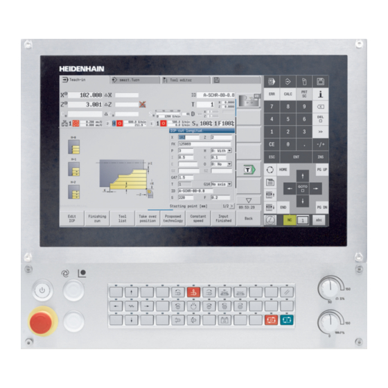
Page 62: Control Screen
This way, you can check cycles, entire cycle programs, and DIN programs. graphics: Display of the contour during ICP ICP contour programming DIN editing window: Display of the DIN program during DIN programming Error window: Display of encountered errors and warnings HEIDENHAIN | MANUALplus 620 | User's Manual | 12/2017... -
Page 63: Operation And Data Input
In some situations, it is not possible to switch modes (e.g. in Tool editor operating mode). In such cases, you need to terminate the editing process or close the dialog before switching the operating mode. HEIDENHAIN | MANUALplus 620 | User's Manual | 12/2017... -
Page 64: Menu Selection
The data are automatically written into the appropriate input fields. Data entries are not concluded until the Save or Input finished soft key has been pressed The Back soft key takes you back to the previous operating level HEIDENHAIN | MANUALplus 620 | User's Manual | 12/2017... -
Page 65: Data Input
You can navigate between the forms and groups with the smart.Turn keys. smart.Turn keys Go to the next form Go to next or previous group HEIDENHAIN | MANUALplus 620 | User's Manual | 12/2017... -
Page 66: List Operations
Wait until the selected character appears in the input field. Then, enter the next character. Use the OK soft key to transfer the text into the open dialog field. To delete individual characters, use the BACKSPACE soft key. HEIDENHAIN | MANUALplus 620 | User's Manual | 12/2017... -
Page 67: Calculator
The CONFIRM VALUE soft key enables you to load the current value from the calculator to the active input field. HEIDENHAIN | MANUALplus 620 | User's Manual | 12/2017... -
Page 68: Using The Calculator
Add value to buffer memory Save the value to buffer memory Recall from buffer memory Delete buffer memory contents Natural logarithm Logarithm Exponent function Check the algebraic sign Form the absolute value Truncate decimal places HEIDENHAIN | MANUALplus 620 | User's Manual | 12/2017... -
Page 69: Adjusting The Position Of The Calculator
ATAN. Adjusting the position of the calculator You can move the calculator as follows: Move the calculator with the arrow keys You can also move the calculator with a connected mouse. HEIDENHAIN | MANUALplus 620 | User's Manual | 12/2017... -
Page 70: Program Types
(cycle programs) smart.Turn and DIN nc_prog\ncps *.nc main programs DIN subprograms nc_prog\ncps *.ncs ICP contours nc_prog\gti Turning contours *.gmi Contours of *.gmr workpiece blanks *.gms Contours on face *.gmm Lateral surface contours HEIDENHAIN | MANUALplus 620 | User's Manual | 12/2017... -
Page 71: Error Messages
The control opens the error window and displays all accumulated error messages. Closing the error window Press the END soft key. Press the ERR key. The control closes the error window. HEIDENHAIN | MANUALplus 620 | User's Manual | 12/2017... -
Page 72: Detailed Error Messages
Press the INTERNAL INFO soft key. The control opens a window with information on the error cause and corrective action. Press the INTERNAL INFO soft key again to close the window. HEIDENHAIN | MANUALplus 620 | User's Manual | 12/2017... -
Page 73: Clearing Errors
Press the DELETE ALL soft key to clear all errors. If the cause of the error has not been corrected, the error message cannot be deleted. In this case, the error message remains in the window. HEIDENHAIN | MANUALplus 620 | User's Manual | 12/2017... -
Page 74: Error Log
The control saves each key pressed during operation in the keystroke log file. The oldest entry is at the beginning of the log file, and the most recent entry is at the end. HEIDENHAIN | MANUALplus 620 | User's Manual | 12/2017... -
Page 75: Saving Service Files
2 to 5. An existing file with the number is deleted. Saving service files Open the error window Press the LOG FILES soft key Press the SAVE SERVICE FILES soft key HEIDENHAIN | MANUALplus 620 | User's Manual | 12/2017... -
Page 76: Turnguide Context-Sensitive Help
.chm files. As an option, your machine tool builder can embed machine-specific documentation in the TURNguide. These documents then appear as a separate book in the main.chm file. HEIDENHAIN | MANUALplus 620 | User's Manual | 12/2017... -
Page 77: Working With The Turnguide
Press the Info key The control starts the help system and shows a description for the active function (does not apply to miscellaneous functions or cycles that were integrated by your machine tool builder). HEIDENHAIN | MANUALplus 620 | User's Manual | 12/2017... - Page 78 If the text window at right is active: Jump back to the window at left HEIDENHAIN | MANUALplus 620 | User's Manual | 12/2017...
- Page 79 TURNguide is open. If the full screen is active, the control reduces the window size automatically before changing the focus. Exit TURNguide HEIDENHAIN | MANUALplus 620 | User's Manual | 12/2017...
- Page 80 The full-text search only works for single words. If you activate the Search only in titles function (by mouse or by pressing the keys), the control searches only through headings and ignores the body text. HEIDENHAIN | MANUALplus 620 | User's Manual | 12/2017...
-
Page 81: Downloading Current Help Files
Swedish Danish TNC:\tncguide\da Finnish TNC:\tncguide\fi Dutch TNC:\tncguide\nl Polish TNC:\tncguide\pl Hungarian TNC:\tncguide\hu Russian TNC:\tncguide\ru Chinese (simplified) TNC:\tncguide\zh Chinese (traditional) TNC:\tncguide\zh-tw Slovenian TNC:\tncguide\sl Norwegian TNC:\tncguide\no Slovak TNC:\tncguide\sk TNC:\tncguide\kr Korean Turkish TNC:\tncguide\tr Romanian TNC:\tncguide\ro HEIDENHAIN | MANUALplus 620 | User's Manual | 12/2017... -
Page 82: Datapilot Programming Station
Operation DataPilot is operated through function keys and numerical keys of the PC keyboard. For more information about installation and operation, please refer to the DataPilot installation and operating instructions. HEIDENHAIN | MANUALplus 620 | User's Manual | 12/2017... -
Page 83: Operating The Touchscreen
Operating the Touchscreen... -
Page 84: Display Unit And Operation
The following keys, for example, can easily be replaced by hand gestures: Function Gesture Shift the soft-key row Swipe horizontally over the soft-key row Soft-key selection keys Tap on the function in the touchscreen HEIDENHAIN | MANUALplus 620 | User's Manual | 12/2017... -
Page 85: Gestures
Continuous contact of fingertip on the screen Swipe Flowing motion over the screen Drag A combination of long-press and then swipe, moving a finger over the screen when the starting point is clear- ly defined HEIDENHAIN | MANUALplus 620 | User's Manual | 12/2017... -
Page 86: Navigating In The Table And Nc Programs
Symbol Gesture Function Mark the NC block or table line Stop scrolling Double tap Activate the table line Edit NC block or unit Swipe Scroll through the NC program or table HEIDENHAIN | MANUALplus 620 | User's Manual | 12/2017... -
Page 87: Operating The Simulation
A combination of long-press and then swipe, moving two fingers in parallel over the screen when the start- ing point is clearly defined Spread Magnify the graphic Pinch Reduce the graphic HEIDENHAIN | MANUALplus 620 | User's Manual | 12/2017... -
Page 88: Using The Heros Menu
Operating the Touchscreen | Gestures Using the HEROS menu You can use the HEROS menu as follows: Symbol Gesture Function Select the application Long press Open the application HEIDENHAIN | MANUALplus 620 | User's Manual | 12/2017... -
Page 89: Functions In The Taskbar
Select the Touchscreen Cleaning menu item The control locks the screen for 90 seconds. Clean the screen If you would like to stop the cleaning mode: Pull the displayed sliders apart at the same time HEIDENHAIN | MANUALplus 620 | User's Manual | 12/2017... -
Page 91: Machine Mode Of Operation
Machine mode of operation... -
Page 92: Machine Mode Of Operation
You can also convert Teach-in programs to smart.Turn programs. This enables you to make use of straightforward Teach-in programming and then optimize or complete the NC program following conversion into format. HEIDENHAIN | MANUALplus 620 | User's Manual | 12/2017... -
Page 93: Switch-On / Switch-Off
This message is correct if configuration parameters were changed The cause for one of the above listed messages can also be a defect in the encoder or control. Please contact your machine supplier if the problem recurs. HEIDENHAIN | MANUALplus 620 | User's Manual | 12/2017... -
Page 94: Reference Submode
The control activates the position display and activates the main menu. In case you traverse the reference marks separately for the X and Z axes, you only traverse in either the X or the Z axis. HEIDENHAIN | MANUALplus 620 | User's Manual | 12/2017... -
Page 95: Switch-Off
Only operate the main switch after being prompted on the screen Restarting the control Proceed as follows to force a restart: Select the Machine operating mode Press the OFF soft key Press the RESTART soft key The control restarts. HEIDENHAIN | MANUALplus 620 | User's Manual | 12/2017... -
Page 96: Machine Data
If the Constant spindle speed soft key is activated, the S value is evaluated in [rev/min]. In Teach-in programs the tool information and technology data are included in the cycle parameters, and in smart.Turn programs they are part of the NC program. HEIDENHAIN | MANUALplus 620 | User's Manual | 12/2017... - Page 97 Transfer of cutting speed and feed rate from the technology data On: Feed per minute (mm/min) Off: Programmed feed rate per revolution (mm/ rev) On: Constant speed (rpm) Off: Constant surface speed (m/min) HEIDENHAIN | MANUALplus 620 | User's Manual | 12/2017...
-
Page 98: Machine-Dependent Variants Of The Tsf Dialog
WP: No. of spindle (machine-dependent) Additional cycle parameter with B axis: BW: Angle in the B axis (machine-dependent) CW: Reverse the tool (machine-dependent) HC: Shoe brake (machine-dependent) DF: Miscellaneous function (machine-dependent) HEIDENHAIN | MANUALplus 620 | User's Manual | 12/2017... - Page 99 (e.g. turret). There is a danger of collision during the tilting movement! Move the tool or the tool carrier to a safe position before entering data HEIDENHAIN | MANUALplus 620 | User's Manual | 12/2017...
- Page 100 Use tools with suitable tool orientation. In the TSF menu, the setting for the WP parameter is changed when you: Run a cycle with another WP parameter setting Select a program in Program run submode HEIDENHAIN | MANUALplus 620 | User's Manual | 12/2017...
- Page 101 (e.g. turret) or the B axis, and a rotation of the tool. There is a danger of collision during the tilting movement and the rotation! Move the tool or the tool carrier to a safe position before entering data HEIDENHAIN | MANUALplus 620 | User's Manual | 12/2017...
-
Page 102: Machine Data Display
W: The distance remaining from the current position to the target position of the active traversing command status: Distance-to-go display and Distance-to-go and protection zone display of status of protection zone monitoring HEIDENHAIN | MANUALplus 620 | User's Manual | 12/2017... - Page 103 Lower field with white background: Actual feed rate Lower field with gray background: Programmed feed rate with stationary slide Slide display and cycle status: Upper field: Programmed feed rate Lower field: Actual feed rate HEIDENHAIN | MANUALplus 620 | User's Manual | 12/2017...
- Page 104 Motor utilization: Utilization of the servo drive with respect to the rated torque Digital axis and spindle motors Analog axis and spindle motors, if set up by the machine tool builder HEIDENHAIN | MANUALplus 620 | User's Manual | 12/2017...
- Page 105 Display of the current values I, K, U and W I: Plane reference in X K: Plane reference in Z U: Shift in X W: Shift in Z Date and time display Display of an integrated logo HEIDENHAIN | MANUALplus 620 | User's Manual | 12/2017...
-
Page 106: Cycle States
On the screen, you can tell the type of feed rate from the unit of measure in the input field. You can change the feed value with the feed compensation (feed override) (range: 0 % to 150 %). controller HEIDENHAIN | MANUALplus 620 | User's Manual | 12/2017... -
Page 107: Spindle
Spindle symbols (S display) Direction of spindle rotation M3 Direction of spindle rotation M4 Spindle stop M5 Spindle is position-looped M19 C axis on spindle motor is active Spindle designations Main spindle Driven tool HEIDENHAIN | MANUALplus 620 | User's Manual | 12/2017... -
Page 108: Pocket Table Setup
The control opens the list. Refer to your machine manual. The turret, magazine and multifix tool systems can be used together on one machine. The machine tool builder defines the number of the multifix pocket. HEIDENHAIN | MANUALplus 620 | User's Manual | 12/2017... -
Page 109: Machine With Turret
Refer to your machine manual. The turret, magazine and multifix tool systems can be used together on one machine. The machine tool builder defines the number of the multifix pocket. HEIDENHAIN | MANUALplus 620 | User's Manual | 12/2017... -
Page 110: Machine With Magazine
TSF menu. Refer to your machine manual. The turret, magazine and multifix tool systems can be used together on one machine. The machine tool builder defines the number of the multifix pocket. HEIDENHAIN | MANUALplus 620 | User's Manual | 12/2017... -
Page 111: Filling The Turret List With Contents From The Tool List
Select the position in the turret assignment list Select and sort the entries in the tool database Use the arrow keys to select the entry in the tool database Load the selected tool into the turret assignment list HEIDENHAIN | MANUALplus 620 | User's Manual | 12/2017... - Page 112 This soft key is available once you press the View soft key. Switch between ascending and descending sorting This soft key is displayed once you press the Turret list soft key. Not active here Close the tool list HEIDENHAIN | MANUALplus 620 | User's Manual | 12/2017...
-
Page 113: Editing The Turret List
Entering the tool ID number directly: Press the ENT key to activate direct input Enter the tool ID number Press the INS key to conclude input Alternative: Press the ESC key to cancel input HEIDENHAIN | MANUALplus 620 | User's Manual | 12/2017... - Page 114 Load the tool number and the tool ID number into the TSF or cycle dialog Close the turret list without loading the tool number and tool ID number into the dialog. Changes to the turret list are retained HEIDENHAIN | MANUALplus 620 | User's Manual | 12/2017...
-
Page 115: Editing The Magazine List
Machine mode of operation) Select Tool change Select the tool with the Magazine list soft key Alternative: Enter the tool ID number directly Change the tool with the Save soft key HEIDENHAIN | MANUALplus 620 | User's Manual | 12/2017... - Page 116 Select Set T, S, F (can only be selected in Machine mode of operation) Select Unload magazine Select the tool Press the Unload soft key Remove the tool from the magazine list with the Save soft key HEIDENHAIN | MANUALplus 620 | User's Manual | 12/2017...
-
Page 117: Tool Call
If a T number is entered in the TSF dialog with an ID number that is not defined in the turret list, then the turret list will be changed accordingly. The existing turret list will be overwritten. HEIDENHAIN | MANUALplus 620 | User's Manual | 12/2017... -
Page 118: Driven Tools
Mirroring does not become effective until the machining of the workpiece, i.e. when the additional tool holder is executing the machining operation. HEIDENHAIN | MANUALplus 620 | User's Manual | 12/2017... -
Page 119: Tool Life Monitoring
The sequence of exchange contain more than one sister tool. The sequence of exchange is a part of the NC program. Further information: smart.Turn and DIN Programming User's Manual HEIDENHAIN | MANUALplus 620 | User's Manual | 12/2017... - Page 120 Machine mode of operation) Select Tool change Press the Magazine list soft key Select the tool Press the Edit the tool soft key Press the New tooth soft key Press the Back soft key HEIDENHAIN | MANUALplus 620 | User's Manual | 12/2017...
-
Page 121: Machine Setup
The control will calculate the workpiece datum Z Alternative: Machine datum Z = workpiece datum Z (offset = 0) Alternative: This makes it possible to enter the datum shift directly in ZN Press the Save soft key HEIDENHAIN | MANUALplus 620 | User's Manual | 12/2017... -
Page 122: Defining Offsets
Press the Z reference and X reference soft key Alternative: Press the All soft key Press the NC start key The control automatically traverses the reference marks. The control refreshes the position display. HEIDENHAIN | MANUALplus 620 | User's Manual | 12/2017... -
Page 123: Setting The Protection Zone
In DIN programming, you deactivate protection zone monitoring with G60 Q1 and reactivate it with G60 Protection zone status Protection zone monitoring active Protection zone monitoring not active HEIDENHAIN | MANUALplus 620 | User's Manual | 12/2017... -
Page 124: Defining The Tool Change Position
It is recommended that you move to the tool change position and load the position with the Take over position soft key. HEIDENHAIN | MANUALplus 620 | User's Manual | 12/2017... -
Page 125: Setting C-Axis Values
Additional parameters for machines with counter spindle: CV: Datum shift in C axis – active angular offset CA: No. of C axis – Selection of C axis (main spindle or counter spindle) HEIDENHAIN | MANUALplus 620 | User's Manual | 12/2017... -
Page 126: Setting Up Machine Dimensions
Press the Back soft key to terminate the calibration process The calibration values measured are saved. Pre-position the tool for the next measuring direction and repeat the procedure (max. 4 measuring directions) HEIDENHAIN | MANUALplus 620 | User's Manual | 12/2017... -
Page 127: Displaying Operating Times
Duration of controlled operation since being put into service Refer to your machine manual. Your machine tool builder can provide further operating time displays. Displaying operating times: Select Setup Select Service Select Display operating times HEIDENHAIN | MANUALplus 620 | User's Manual | 12/2017... -
Page 128: Configuring The Hr 550Fs Wireless Handwheel
The control saves the serial number of the inserted wireless handwheel and shows it in the configuration window on the left next to the Connect HW button. To save the configuration and exit the configuration menu, press the END button HEIDENHAIN | MANUALplus 620 | User's Manual | 12/2017... - Page 129 Select the Set up wireless handwheel menu item Click the Set power button The control displays the three available power settings. Click the desired setting. To save the configuration and exit the configuration menu, press the END button HEIDENHAIN | MANUALplus 620 | User's Manual | 12/2017...
- Page 130 If this occurs, try to improve the transmission quality by selecting another channel or by increasing the transmitter power. "Setting the transmission channel", Further information: Page 129 "Selecting the transmitter power", Further information: Page 129 HEIDENHAIN | MANUALplus 620 | User's Manual | 12/2017...
-
Page 131: Setting The System Time
Select Adjust the system time Select Synchronize the time over NTP server (if available) Select Set the time manually Select Date Enter the Time Select Time zone Press the OK soft key HEIDENHAIN | MANUALplus 620 | User's Manual | 12/2017... -
Page 132: Tool Measurement
The compensation values are deleted during tool measurement. Please note that for drilling and milling tools the center is measured. The tools' type and orientation determine how they are measured. Note the help graphics HEIDENHAIN | MANUALplus 620 | User's Manual | 12/2017... -
Page 133: Touch-Off
Turn the measuring diameter Enter the diameter value as Measuring pt. coordinate X and save it For turning tools, enter the cutting edge radius and load it into the tool table HEIDENHAIN | MANUALplus 620 | User's Manual | 12/2017... -
Page 134: Touch Probe (Tool Touch Probe)
The tool moves in the measuring direction. When it contacts the touch probe, the control calculates and saves the set-up dimensions. For turning tools, enter the cutting edge radius and load it into the tool table HEIDENHAIN | MANUALplus 620 | User's Manual | 12/2017... -
Page 135: Optical Gauge
Save the tool dimension in Z Save the tool dimension in X For turning tools, enter the cutting edge radius and load it into the tool table HEIDENHAIN | MANUALplus 620 | User's Manual | 12/2017... -
Page 136: Tool Compensation
The value will be displayed in the distance-to-go display. Transfer the compensation value to the tool table The T display shows the new compensation value. The distance-to-go display is cleared. HEIDENHAIN | MANUALplus 620 | User's Manual | 12/2017... - Page 137 Select Set T, S, F (can only be selected in Machine mode of operation) Press the Tool correct. soft key Press the Delete soft key Delete compensation value in X (or Z) HEIDENHAIN | MANUALplus 620 | User's Manual | 12/2017...
-
Page 138: Manual Operation
The maximum executable spindle speed varies depending on the machine. It may differ significantly from the maximum programmable spindle speed. The machine tool builder defines the maximum executable spindle speed in the machine parameters. HEIDENHAIN | MANUALplus 620 | User's Manual | 12/2017... -
Page 139: Handwheel Operation
Select the cycle and enter the cycle parameters Graphically check the cycle run Run the cycle The entries last made in a cycle dialog remain in memory until a new cycle is selected. HEIDENHAIN | MANUALplus 620 | User's Manual | 12/2017... -
Page 140: Teach-In Submode
The cycle block contains: Block number Tool used (number and tool ID number) Cycle name Number of the ICP contour or of the DIN subprogram (after the % character) HEIDENHAIN | MANUALplus 620 | User's Manual | 12/2017... -
Page 141: Programming Teach-In Cycles
Copy cycle soft key. Insert copied data from the buffer Change the cycle parameter or cycle mode. The cycle type, however, cannot be changed. Insert a new cycle below the highlighted block HEIDENHAIN | MANUALplus 620 | User's Manual | 12/2017... -
Page 142: Program Run Submode
"Program management", Page 164 Programs selected in Program run submode are protected from deletion. To enable the file for deletion, exit the program block display by pressing the Back soft key. HEIDENHAIN | MANUALplus 620 | User's Manual | 12/2017... -
Page 143: Comparing Tool Lists
Check the turret assignment list manually after it has been overwritten This function is also available on machines with a tool magazine. The control uses the magazine list instead of the turret list. HEIDENHAIN | MANUALplus 620 | User's Manual | 12/2017... -
Page 144: Before Executing A Program
Teach-in/DIN program in the list window. With Teach-in programs, the parameters of the cycle that is highlighted are displayed. Graphic verification: The program run can be verified in Simulation submode Further information: "Simulation submode", Page 530 HEIDENHAIN | MANUALplus 620 | User's Manual | 12/2017... -
Page 145: Block Scan
T command. The control restores the previous machine situation by proceeding in the following sequence: Insert the tool Position the axes in the configured or selected sequence Switch the spindle on HEIDENHAIN | MANUALplus 620 | User's Manual | 12/2017... -
Page 146: Program Execution
Start blck search soft key. The cursor goes to the first block of the Teach-in program or DIN program Enables you to enter into an NC program at a selected point HEIDENHAIN | MANUALplus 620 | User's Manual | 12/2017... - Page 147 Select the No.pieces menu item The control opens the No.pieces form. Cycle parameters: MP: Default unit quantity P: Actual unit quantity With the Delete qty. parts soft key, you can reset the workpiece counter. HEIDENHAIN | MANUALplus 620 | User's Manual | 12/2017...
- Page 148 To deactivate the skip levels, program the NR parameter without a value and press Save. When setting and activating skip levels during program run, please remember that the control will respond with a delay due to the block scan. HEIDENHAIN | MANUALplus 620 | User's Manual | 12/2017...
- Page 149 You can now change the variables as desired. Please note that you can only change variables while the program is not running (not started yet or stopped). HEIDENHAIN | MANUALplus 620 | User's Manual | 12/2017...
-
Page 150: Automatic Job
Select the Job selection menu item Select Automatic job Press the Open soft key Select the start program with the cursor if necessary Confirm with the Take over job soft key HEIDENHAIN | MANUALplus 620 | User's Manual | 12/2017... - Page 151 Select the Switch off job list menu item This menu item switches to the NC program display. Alternative: Select the Switch on job list menu item This menu item switches to the job display. HEIDENHAIN | MANUALplus 620 | User's Manual | 12/2017...
-
Page 152: Entering Compensation Values During Program Run
The control moves in the compensation direction by the compensation value in the following traverse block To delete a compensation, enter the current compensation value with the opposite algebraic sign HEIDENHAIN | MANUALplus 620 | User's Manual | 12/2017... - Page 153 The compensation values are saved in an internal table and are available in any program Delete all additive compensation values when you set up the machine again HEIDENHAIN | MANUALplus 620 | User's Manual | 12/2017...
-
Page 154: Program Execution In Dry Run Mode
Reduce the feed rate with the override potentiometer if necessary After deactivation of dry run mode, the control returns to the programmed feed rates and the programmed spindle speed. HEIDENHAIN | MANUALplus 620 | User's Manual | 12/2017... -
Page 155: Load Monitoring (Optional)
As an alternative to the automatic evaluation of the diagnostic bits by the tool life monitoring function, you can also evaluate the diagnostic bits in your program. HEIDENHAIN | MANUALplus 620 | User's Manual | 12/2017... - Page 156 Cutting depth > 1 mm Longitudinal Recessing: Cutting depth > 1 mm Drilling into solid material: Hole diameter > 10 mm HEIDENHAIN | MANUALplus 620 | User's Manual | 12/2017...
-
Page 157: Reference Machining
Press the OK soft key Program M30 or M99 to conclude reference machining. If the program is aborted during machining, no reference data is saved. In this case you need to execute reference machining again. HEIDENHAIN | MANUALplus 620 | User's Manual | 12/2017... - Page 158 Defining new zones Deleting existing zones Changing zone numbers Changing, adding or removing axes within a zone Changing feed rates or spindle speeds Changing tools Changing cutting depth values HEIDENHAIN | MANUALplus 620 | User's Manual | 12/2017...
-
Page 159: Checking The Reference Values
PG2: Limit value – Utilization limit 2 W: Utilization sum during reference machining WA: Utilization sum during the current machining operation WGF: Limit value factor – Factor for the limit of the utilization HEIDENHAIN | MANUALplus 620 | User's Manual | 12/2017... - Page 160 Magenta: Maximum utilization sum during last machining operation (WA) After reference machining, the value W equals WA and the value P equals PA. They are used as the reference values for calculating the limit values. HEIDENHAIN | MANUALplus 620 | User's Manual | 12/2017...
-
Page 161: Adapting The Limit Values
Save soft key! Reference machining does not have to be repeated after adapting the limit values. You can continue production with the adapted limit values. HEIDENHAIN | MANUALplus 620 | User's Manual | 12/2017... -
Page 162: Using Load Monitoring During Production
Red: Current peak value between PG1 and limit value 2 (PG1) Thin lower bar (display standardized to reference value 1): Green: Current utilization sum (WA) Yellow: Current utilization sum up to the limit value (WGF) HEIDENHAIN | MANUALplus 620 | User's Manual | 12/2017... -
Page 163: 4.11 Graphic Simulation
In Program run submode the simulation starts from the cursor position. smart.Turn and DIN programs are simulated from the beginning of the program. Further information: "Simulation submode", Page 530 HEIDENHAIN | MANUALplus 620 | User's Manual | 12/2017... -
Page 164: 4.12 Program Management
Open the alphabetic keyboard Further information: "Alphabetic keyboard", Page 66 Open the program for the automatic start Close the program selection dialog. The program previously active in Program run submode remains effective HEIDENHAIN | MANUALplus 620 | User's Manual | 12/2017... - Page 165 Sort the programs by file size Sort the programs by change date Update the marked program Reverse the sorting direction Open the program for the automatic start Return to program selection dialog HEIDENHAIN | MANUALplus 620 | User's Manual | 12/2017...
-
Page 166: File Manager
Return to the program selection dialog Other soft keys Display details Mark all files Update the marked program Activate/deactivate write protection for the marked program Open the alphabetic keyboard Return to the program selection dialog HEIDENHAIN | MANUALplus 620 | User's Manual | 12/2017... -
Page 167: Project Management
Pictures) have predefined names that must not be changed. All existing project folders are displayed in the project management. Use the file manager to switch between subfolders. HEIDENHAIN | MANUALplus 620 | User's Manual | 12/2017... -
Page 168: 4.13 Conversion Into Din Format
If a program with the name used is open in the smart.Turn editor, the conversion must be confirmed with the Overwrite soft key. The control overwrites the program that is open in the smart.Turn editor. HEIDENHAIN | MANUALplus 620 | User's Manual | 12/2017... -
Page 169: 4.14 Units Of Measure
New programs are created in the selected unit Refer to your machine manual if you want to know whether and how the handwheel resolution can be set to inches HEIDENHAIN | MANUALplus 620 | User's Manual | 12/2017... -
Page 171: Teach-In
Teach-in... -
Page 172: Working With Cycles
The control does not automatically check whether collisions can occur between the tool and the workpiece. There is danger of collision during the approach movement! If necessary, program an additional rapid traverse path to a safe auxiliary position HEIDENHAIN | MANUALplus 620 | User's Manual | 12/2017... -
Page 173: Help Graphics
Use DIN cycles without datum shifts Graphical test run (simulation) Before executing a cycle, you can graphically test the contour details and the machining sequence. Further information: "Simulation submode", Page 530 HEIDENHAIN | MANUALplus 620 | User's Manual | 12/2017... -
Page 174: Contour Follow-Up In Teach-In Submode
Move the axes with the manual direction keys or the handwheel Terminate the machining process with the BACK soft key HEIDENHAIN | MANUALplus 620 | User's Manual | 12/2017... -
Page 175: Switching Functions (M Functions)
Create and select a cycle Press the Change text soft key Press the GOTO key to show the alphabetic keyboard Enter the comment with the on-screen alphabetic keyboard Apply the comment HEIDENHAIN | MANUALplus 620 | User's Manual | 12/2017... -
Page 176: Cycle Menu
Milling cycles and patterns for face and later- al-surface machining DIN cycle Including DIN macros Soft keys in cycle programming: Depending on the type of cycle, you define the variants of the cycle by soft key. HEIDENHAIN | MANUALplus 620 | User's Manual | 12/2017... - Page 177 Circular drilling and milling patterns on face or lateral surface Apply entered or changed values Cancel the current dialog If you have confirmed the cycle with the Input finished soft key, a further soft-key row is displayed. HEIDENHAIN | MANUALplus 620 | User's Manual | 12/2017...
- Page 178 Teach-in submode", Page 179 Initiate cycle in Program Run, Single Block Display basic blocks Display simulation Save the cycle (only with Add cycle) Overwrite the cycle (only with Edit cycle) Return to cycle description HEIDENHAIN | MANUALplus 620 | User's Manual | 12/2017...
-
Page 179: Tool Compensation In Teach-In Submode
Determine the compensation value by handwheel; the value is shown in the distance- to-go display Alternative: Enter the compensation value dx (or dz, dy) Press the Save or Overwrite soft key HEIDENHAIN | MANUALplus 620 | User's Manual | 12/2017... -
Page 180: Addresses Used In Many Cycles
With the address Dxx you activate an additive compensation for the entire cycle run. The xx stands for the compensation numbers 1 to 16. The additive compensation is switched off again at the end of the cycle. HEIDENHAIN | MANUALplus 620 | User's Manual | 12/2017... -
Page 181: Workpiece Blank Cycles
Opposing spindle for rear-face machining RG: Activate contour follow-up – Contour follow-up for Teach- in submode Further information: "Contour follow-up in Teach-in submode", Page 174 0: Without contour follow-up 1: With contour follow-up HEIDENHAIN | MANUALplus 620 | User's Manual | 12/2017... -
Page 182: Icp Workpiece Blank Contour
Opposing spindle for rear-face machining RG: Activate contour follow-up – Contour follow-up for Teach- in submode "Contour follow-up in Teach-in submode", Further information: Page 174 0: Without contour follow-up 1: With contour follow-up HEIDENHAIN | MANUALplus 620 | User's Manual | 12/2017... -
Page 183: Single Cut Cycles
Single longitudinal/transverse cut Linear machining in angle Single oblique Circular machining Single circular cut (for cutting direction, see menu item) Cham Machine a chamfer Round. Machine a rounding Call an M function HEIDENHAIN | MANUALplus 620 | User's Manual | 12/2017... -
Page 184: Rap. Trav. Positioning
(machine-dependent) Main drive Opposing spindle for rear-face machining BW: Angle in the B axis (machine-dependent) CW: Reverse the tool (machine-dependent) HC: Shoe brake (machine-dependent) DF: Miscellaneous function (machine-dependent) HEIDENHAIN | MANUALplus 620 | User's Manual | 12/2017... -
Page 185: Approaching The Tool Change Position
(machine-dependent) Main drive Opposing spindle for rear-face machining BW: Angle in the B axis (machine-dependent) CW: Reverse the tool (machine-dependent) HC: Shoe brake (machine-dependent) DF: Miscellaneous function (machine-dependent) HEIDENHAIN | MANUALplus 620 | User's Manual | 12/2017... -
Page 186: Linear Mach. Longit
1 Move from Start point to Start point contour X1 2 Move to End point contour Z2 at programmed feed rate 3 Retract and return to Start point on paraxial path HEIDENHAIN | MANUALplus 620 | User's Manual | 12/2017... -
Page 187: Transv. Linear Maching
1 Move from Start point to Start point contour Z1 2 Move to End point contour X2 at programmed feed rate 3 Retract and return to Start point on paraxial path HEIDENHAIN | MANUALplus 620 | User's Manual | 12/2017... -
Page 188: Linear Machining In Angle
CW: Reverse the tool (machine-dependent) HC: Shoe brake (machine-dependent) DF: Miscellaneous function (machine-dependent) Type of machining for technology database access: Finishing Parameter combinations for defining the target point: see help graphic HEIDENHAIN | MANUALplus 620 | User's Manual | 12/2017... - Page 189 2 Move on linear path from Start point to Start point contour X1, 3 Move to Target position at programmed feed rate 4 Retract and return to Start point on paraxial path HEIDENHAIN | MANUALplus 620 | User's Manual | 12/2017...
-
Page 190: Circular Machining
Opposing spindle for rear-face machining BW: Angle in the B axis (machine-dependent) CW: Reverse the tool (machine-dependent) HC: Shoe brake (machine-dependent) DF: Miscellaneous function (machine-dependent) Type of machining for technology database access: Finishing HEIDENHAIN | MANUALplus 620 | User's Manual | 12/2017... - Page 191 1 Move on paraxial path from Start point to Start point contour X1, Z1 2 Move in circular arc to End point contour X2, Z2 at programmed feed rate 3 Retract and return to Start point on paraxial path HEIDENHAIN | MANUALplus 620 | User's Manual | 12/2017...
-
Page 192: Chamfer
Opposing spindle for rear-face machining BW: Angle in the B axis (machine-dependent) CW: Reverse the tool (machine-dependent) HC: Shoe brake (machine-dependent) DF: Miscellaneous function (machine-dependent) Type of machining for technology database access: Finishing HEIDENHAIN | MANUALplus 620 | User's Manual | 12/2017... - Page 193 2 Move on paraxial path from Start point to chamfer starting point 3 Move to chamfer end point at programmed feed rate 4 Retract and return to Start point on paraxial path HEIDENHAIN | MANUALplus 620 | User's Manual | 12/2017...
-
Page 194: Rounding
Opposing spindle for rear-face machining BW: Angle in the B axis (machine-dependent) CW: Reverse the tool (machine-dependent) HC: Shoe brake (machine-dependent) DF: Miscellaneous function (machine-dependent) Type of machining for technology database access: Finishing HEIDENHAIN | MANUALplus 620 | User's Manual | 12/2017... - Page 195 2 Move on paraxial path from Start point to rounding starting point 3 Move in circular arc to end point of rounding at programmed feed rate. 4 Retract and return to Start point on paraxial path HEIDENHAIN | MANUALplus 620 | User's Manual | 12/2017...
-
Page 196: M Functions
Conclude entry Press the NC start key Spindle stop M19 (spindle positioning): Select Single cuts Select M function Activate M19 Enter the stopping angle Conclude entry Press the NC start key HEIDENHAIN | MANUALplus 620 | User's Manual | 12/2017... -
Page 197: Turning Cycles
Roughing and finishing cycle for any type of contour (cutting paths parallel to finished part) ICP cut longitud./ICP cut transv. Roughing and finishing cycle for any type of contour HEIDENHAIN | MANUALplus 620 | User's Manual | 12/2017... -
Page 198: Tool Position
Basic mode Oblique cut at contour end Expanded mode Rounding in contour valley (in both corners) Expanded mode Chamfer (or rounding) at contour start Expanded mode Chamfer (or rounding) at contour end HEIDENHAIN | MANUALplus 620 | User's Manual | 12/2017... -
Page 199: Cut Longitud
Opposing spindle for rear-face machining BW: Angle in the B axis (machine-dependent) CW: Reverse the tool (machine-dependent) HC: Shoe brake (machine-dependent) DF: Miscellaneous function (machine-dependent) Type of machining for technology database access: Roughing HEIDENHAIN | MANUALplus 620 | User's Manual | 12/2017... - Page 200 6 Repeat 3 to 5 until the Start point contour X1 is reached 7 Return to the Start point on a diagonal path 8 Move to the Tool change point according to the setting in G14 HEIDENHAIN | MANUALplus 620 | User's Manual | 12/2017...
-
Page 201: Cut Transv
Opposing spindle for rear-face machining BW: Angle in the B axis (machine-dependent) CW: Reverse the tool (machine-dependent) HC: Shoe brake (machine-dependent) DF: Miscellaneous function (machine-dependent) Type of machining for technology database access: Roughing HEIDENHAIN | MANUALplus 620 | User's Manual | 12/2017... - Page 202 6 Repeat 3 to 5 until the Start point contour Z1 is reached 7 Return to the Start point on a diagonal path 8 Move to the Tool change point according to the setting in G14 HEIDENHAIN | MANUALplus 620 | User's Manual | 12/2017...
-
Page 203: Cut Longitud.-Expanded
MFS: M at beginning: M function that is executed at the beginning of the machining step MFE: M at end: M function that is executed at the end of the machining step HEIDENHAIN | MANUALplus 620 | User's Manual | 12/2017... - Page 204 6 Repeat 3 to 5 until the Start point contour X1 is reached 7 Return to the Start point on a paraxial path 8 Move to the Tool change point according to the setting in G14 HEIDENHAIN | MANUALplus 620 | User's Manual | 12/2017...
-
Page 205: Cut Transv.-Expanded
MFS: M at beginning: M function that is executed at the beginning of the machining step MFE: M at end: M function that is executed at the end of the machining step HEIDENHAIN | MANUALplus 620 | User's Manual | 12/2017... - Page 206 6 Repeat 3 to 5 until the Start point contour Z1 is reached 7 Return to the Start point on a paraxial path 8 Move to the Tool change point according to the setting in G14 HEIDENHAIN | MANUALplus 620 | User's Manual | 12/2017...
-
Page 207: Finishing Cut Longitud
Opposing spindle for rear-face machining BW: Angle in the B axis (machine-dependent) CW: Reverse the tool (machine-dependent) HC: Shoe brake (machine-dependent) DF: Miscellaneous function (machine-dependent) Type of machining for technology database access: Finishing HEIDENHAIN | MANUALplus 620 | User's Manual | 12/2017... - Page 208 2 Finish first in longitudinal direction, then in transverse direction 3 Return in longitudinal direction to the Start point 4 Move to the Tool change point according to the setting in G14 HEIDENHAIN | MANUALplus 620 | User's Manual | 12/2017...
-
Page 209: Finishing Cut Transv
Opposing spindle for rear-face machining BW: Angle in the B axis (machine-dependent) CW: Reverse the tool (machine-dependent) HC: Shoe brake (machine-dependent) DF: Miscellaneous function (machine-dependent) Type of machining for technology database access: Finishing HEIDENHAIN | MANUALplus 620 | User's Manual | 12/2017... - Page 210 2 Finish first in transverse direction, then in longitudinal direction 3 Return in transverse direction to the Start point 4 Move to the Tool change point according to the setting in G14 HEIDENHAIN | MANUALplus 620 | User's Manual | 12/2017...
-
Page 211: Finishing Cut Longitud.-Expanded
WP: No. of spindle – Displays which workpiece spindle is used to execute the cycle (machine-dependent) Main drive Opposing spindle for rear-face machining BW: Angle in the B axis (machine-dependent) CW: Reverse the tool (machine-dependent) HEIDENHAIN | MANUALplus 620 | User's Manual | 12/2017... - Page 212 2 Finish the contour area from the Start point contour X1, Z1 to the End point contour X2, Z2, taking the optional contour elements into account 3 Move to the Tool change point according to the setting in G14 HEIDENHAIN | MANUALplus 620 | User's Manual | 12/2017...
-
Page 213: Finishing Cut Transv.-Expanded
WP: No. of spindle – Displays which workpiece spindle is used to execute the cycle (machine-dependent) Main drive Opposing spindle for rear-face machining BW: Angle in the B axis (machine-dependent) CW: Reverse the tool (machine-dependent) HEIDENHAIN | MANUALplus 620 | User's Manual | 12/2017... - Page 214 2 Finish the contour area from the Start point contour X1, Z1 to the End point contour X2, Z2, taking the optional contour elements into account 3 Move to the Tool change point according to the setting in G14 HEIDENHAIN | MANUALplus 620 | User's Manual | 12/2017...
-
Page 215: Cutting, Longitudinal Plunge
(machine-dependent) Main drive Opposing spindle for rear-face machining BW: Angle in the B axis (machine-dependent) CW: Reverse the tool (machine-dependent) HC: Shoe brake (machine-dependent) DF: Miscellaneous function (machine-dependent) HEIDENHAIN | MANUALplus 620 | User's Manual | 12/2017... - Page 216 7 Repeat 3 to 6 until the End point contour X2 is reached 8 Return to the Start point on a paraxial path 9 Move to the Tool change point according to the setting in G14 HEIDENHAIN | MANUALplus 620 | User's Manual | 12/2017...
-
Page 217: Cutting, Transverse Plunge
(machine-dependent) Main drive Opposing spindle for rear-face machining BW: Angle in the B axis (machine-dependent) CW: Reverse the tool (machine-dependent) HC: Shoe brake (machine-dependent) DF: Miscellaneous function (machine-dependent) HEIDENHAIN | MANUALplus 620 | User's Manual | 12/2017... - Page 218 7 Repeat 3 to 6 until the End point contour Z2 is reached 8 Return to the Start point on a paraxial path 9 Move to the Tool change point according to the setting in G14 HEIDENHAIN | MANUALplus 620 | User's Manual | 12/2017...
-
Page 219: Cutting, Longitudinal Plunge-Expanded
MFS: M at beginning: M function that is executed at the beginning of the machining step MFE: M at end: M function that is executed at the end of the machining step HEIDENHAIN | MANUALplus 620 | User's Manual | 12/2017... - Page 220 7 Repeat 3 to 6 until the End point contour X2 is reached 8 Return to the Start point on a paraxial path 9 Move to the Tool change point according to the setting in G14 HEIDENHAIN | MANUALplus 620 | User's Manual | 12/2017...
-
Page 221: Cutting, Transverse Plunge-Expanded
MFS: M at beginning: M function that is executed at the beginning of the machining step MFE: M at end: M function that is executed at the end of the machining step HEIDENHAIN | MANUALplus 620 | User's Manual | 12/2017... - Page 222 7 Repeat 3 to 6 until the End point contour Z2 is reached 8 Return to the Start point on a paraxial path 9 Move to the Tool change point according to the setting in G14 HEIDENHAIN | MANUALplus 620 | User's Manual | 12/2017...
-
Page 223: Longitudinal Cutting, Finishing Plunge
Opposing spindle for rear-face machining BW: Angle in the B axis (machine-dependent) CW: Reverse the tool (machine-dependent) HC: Shoe brake (machine-dependent) DF: Miscellaneous function (machine-dependent) Type of machining for technology database access: Finishing HEIDENHAIN | MANUALplus 620 | User's Manual | 12/2017... - Page 224 X1, Z1 2 Finish the defined contour area 3 Return to the Start point on a paraxial path 4 Move to the Tool change point according to the setting in G14 HEIDENHAIN | MANUALplus 620 | User's Manual | 12/2017...
-
Page 225: Traverse Cutting, Finishing Plunge
Opposing spindle for rear-face machining BW: Angle in the B axis (machine-dependent) CW: Reverse the tool (machine-dependent) HC: Shoe brake (machine-dependent) DF: Miscellaneous function (machine-dependent) Type of machining for technology database access: Finishing HEIDENHAIN | MANUALplus 620 | User's Manual | 12/2017... - Page 226 X1, Z1 2 Finish the defined contour area 3 Return to the Start point on a paraxial path 4 Move to the Tool change point according to the setting in G14 HEIDENHAIN | MANUALplus 620 | User's Manual | 12/2017...
-
Page 227: Longitudinal Cutting, Finishing Plunge-Expanded
MFS: M at beginning: M function that is executed at the beginning of the machining step MFE: M at end: M function that is executed at the end of the machining step HEIDENHAIN | MANUALplus 620 | User's Manual | 12/2017... - Page 228 1 Move on paraxial path from Start point to Start point contour X1, Z1 2 Finish the defined contour area, taking the optional contour elements into account 3 Move to the Tool change point according to the setting in G14 HEIDENHAIN | MANUALplus 620 | User's Manual | 12/2017...
-
Page 229: Transverse Cutting, Finishing Plunge—Expanded
MFS: M at beginning: M function that is executed at the beginning of the machining step MFE: M at end: M function that is executed at the end of the machining step HEIDENHAIN | MANUALplus 620 | User's Manual | 12/2017... - Page 230 1 Move on paraxial path from Start point to Start point contour X1, Z1 2 Finish the defined contour area, taking the optional contour elements into account 3 Move to the Tool change point according to the setting in G14 HEIDENHAIN | MANUALplus 620 | User's Manual | 12/2017...
-
Page 231: Cutting, Longitudinal, Icp Contour-Parallel
J > 0: The cycle machines the area defined by the workpiece blank oversize HR: Main machining direction SX, SZ: Cutting limit in X and Z Further information: "Cutting limits SX, SZ", Page 180 HEIDENHAIN | MANUALplus 620 | User's Manual | 12/2017... - Page 232 Opposing spindle for rear-face machining BW: Angle in the B axis (machine-dependent) CW: Reverse the tool (machine-dependent) HC: Shoe brake (machine-dependent) DF: Miscellaneous function (machine-dependent) Type of machining for technology database access: Roughing HEIDENHAIN | MANUALplus 620 | User's Manual | 12/2017...
- Page 233 5 Repeat 3 to 4 until the defined area has been machined 6 Return to the Start point on a paraxial path 7 Move to the Tool change point according to the setting in G14 HEIDENHAIN | MANUALplus 620 | User's Manual | 12/2017...
-
Page 234: Cutting, Transverse, Icp Contour-Parallel
J > 0: The cycle machines the area defined by the workpiece blank oversize HR: Main machining direction SX, SZ: Cutting limit in X and Z Further information: "Cutting limits SX, SZ", Page 180 HEIDENHAIN | MANUALplus 620 | User's Manual | 12/2017... - Page 235 Opposing spindle for rear-face machining BW: Angle in the B axis (machine-dependent) CW: Reverse the tool (machine-dependent) HC: Shoe brake (machine-dependent) DF: Miscellaneous function (machine-dependent) Type of machining for technology database access: Roughing HEIDENHAIN | MANUALplus 620 | User's Manual | 12/2017...
- Page 236 5 Repeat 3 to 4 until the defined area has been machined 6 Return to the Start point on a paraxial path 7 Move to the Tool change point according to the setting in G14 HEIDENHAIN | MANUALplus 620 | User's Manual | 12/2017...
-
Page 237: Cutting, Longitudinal, Icp Contour-Parallel, Finishing
Opposing spindle for rear-face machining BW: Angle in the B axis (machine-dependent) CW: Reverse the tool (machine-dependent) HC: Shoe brake (machine-dependent) DF: Miscellaneous function (machine-dependent) Type of machining for technology database access: Finishing HEIDENHAIN | MANUALplus 620 | User's Manual | 12/2017... - Page 238 1 Move on a paraxial path from the Start point to the ICP contour starting point 2 Finish the defined contour area 3 Move to the Tool change point according to the setting in G14 HEIDENHAIN | MANUALplus 620 | User's Manual | 12/2017...
-
Page 239: Cutting, Transverse, Icp Contour-Parallel, Finishing
Opposing spindle for rear-face machining BW: Angle in the B axis (machine-dependent) CW: Reverse the tool (machine-dependent) HC: Shoe brake (machine-dependent) DF: Miscellaneous function (machine-dependent) Type of machining for technology database access: Finishing HEIDENHAIN | MANUALplus 620 | User's Manual | 12/2017... - Page 240 1 Move on a paraxial path from the Start point to the ICP contour starting point 2 Finish the defined contour area 3 Move to the Tool change point according to the setting in G14 HEIDENHAIN | MANUALplus 620 | User's Manual | 12/2017...
-
Page 241: Icp Cut Longitud
The chip is broken by the (intermittent) interruption of the feed. A: Start angle (reference: Z axis; default: parallel to Z axis) W: Depart.angle (reference: Z axis; default: orthogonal to Z axis) HEIDENHAIN | MANUALplus 620 | User's Manual | 12/2017... - Page 242 7 Repeat 3 to 6 until the defined area has been machined 8 Return to the Start point on a paraxial path 9 Move to the Tool change point according to the setting in G14 HEIDENHAIN | MANUALplus 620 | User's Manual | 12/2017...
-
Page 243: Icp Cutting Transverse
The chip is broken by the (intermittent) interruption of the feed. A: Start angle (reference: Z axis; default: parallel to Z axis) W: Depart.angle (reference: Z axis; default: orthogonal to Z axis) HEIDENHAIN | MANUALplus 620 | User's Manual | 12/2017... - Page 244 7 Repeat 3 to 6 until the defined area has been machined 8 Return to the Start point on a paraxial path 9 Move to the Tool change point according to the setting in G14 HEIDENHAIN | MANUALplus 620 | User's Manual | 12/2017...
-
Page 245: Longitudinal Icp Cutting, Finishing
Opposing spindle for rear-face machining BW: Angle in the B axis (machine-dependent) CW: Reverse the tool (machine-dependent) HC: Shoe brake (machine-dependent) DF: Miscellaneous function (machine-dependent) Type of machining for technology database access: Finishing HEIDENHAIN | MANUALplus 620 | User's Manual | 12/2017... - Page 246 1 Move on a paraxial path from the Start point to the ICP contour starting point 2 Finish the defined contour area 3 Move to the Tool change point according to the setting in G14 HEIDENHAIN | MANUALplus 620 | User's Manual | 12/2017...
-
Page 247: Transverse Icp Cutting, Finishing
Opposing spindle for rear-face machining BW: Angle in the B axis (machine-dependent) CW: Reverse the tool (machine-dependent) HC: Shoe brake (machine-dependent) DF: Miscellaneous function (machine-dependent) Type of machining for technology database access: Finishing HEIDENHAIN | MANUALplus 620 | User's Manual | 12/2017... - Page 248 1 Move on a paraxial path from the Start point to the ICP contour starting point 2 Finish the defined contour area 3 Move to the Tool change point according to the setting in G14 HEIDENHAIN | MANUALplus 620 | User's Manual | 12/2017...
-
Page 249: Examples Of Turning Cycles
X-axis direction. Tool data: Turning tool (for external machining) TO = 1 – Tool orientation A = 93° – Tool angle B = 55° – Point angle HEIDENHAIN | MANUALplus 620 | User's Manual | 12/2017... - Page 250 X-axis direction. Tool data: Turning tool (for internal machining) TO = 7 – Tool orientation A = 93° – Tool angle B = 55° – Point angle HEIDENHAIN | MANUALplus 620 | User's Manual | 12/2017...
- Page 251 X-axis direction. Tool data: Turning tool (for external machining) TO = 1 – Tool orientation A = 93° – Tool angle B = 55° – Point angle HEIDENHAIN | MANUALplus 620 | User's Manual | 12/2017...
- Page 252 The Start point contour Z1 parameter was determined during simulation of the first step. Tool data: Turning tool (for external machining) TO = 3 – Tool orientation A = 93° – Tool angle B = 55° – Point angle HEIDENHAIN | MANUALplus 620 | User's Manual | 12/2017...
-
Page 253: Recessing Cycles
Undercut. Form H Undercut type H Undercut. Form K Undercut type K Undercut. Form U Undercut type U Cut-off Cycle for parting the workpiece HEIDENHAIN | MANUALplus 620 | User's Manual | 12/2017... -
Page 254: Undercut Position
Oblique cut at contour end Expanded mode Rounding arc in both corners of contour valley Expanded mode Chamfer or rounding arc at contour start Expanded mode Chamfer or rounding arc at contour end HEIDENHAIN | MANUALplus 620 | User's Manual | 12/2017... -
Page 255: Recessing Radial
Opposing spindle for rear-face machining BW: Angle in the B axis (machine-dependent) CW: Reverse the tool (machine-dependent) HC: Shoe brake (machine-dependent) DF: Miscellaneous function (machine-dependent) Type of machining for technology database access: Contour recessing HEIDENHAIN | MANUALplus 620 | User's Manual | 12/2017... - Page 256 7 Repeat 2 to 6 until all recesses have been machined 8 Return to the Start point on a paraxial path 9 Move to the Tool change point according to the setting in G14 HEIDENHAIN | MANUALplus 620 | User's Manual | 12/2017...
-
Page 257: Recessing Axial
Opposing spindle for rear-face machining BW: Angle in the B axis (machine-dependent) CW: Reverse the tool (machine-dependent) HC: Shoe brake (machine-dependent) DF: Miscellaneous function (machine-dependent) Type of machining for technology database access: Contour recessing HEIDENHAIN | MANUALplus 620 | User's Manual | 12/2017... - Page 258 7 Repeat 2 to 6 until all recesses have been machined 8 Return to the Start point on a paraxial path 9 Move to the Tool change point according to the setting in G14 HEIDENHAIN | MANUALplus 620 | User's Manual | 12/2017...
-
Page 259: Recessing Radial—Expanded
MFS: M at beginning: M function that is executed at the beginning of the machining step MFE: M at end: M function that is executed at the end of the machining step HEIDENHAIN | MANUALplus 620 | User's Manual | 12/2017... - Page 260 7 Repeat 2 to 6 until all recesses have been machined 8 Return to the Start point on a paraxial path 9 Move to the Tool change point according to the setting in G14 HEIDENHAIN | MANUALplus 620 | User's Manual | 12/2017...
-
Page 261: Recessing Axial—Expanded
MFS: M at beginning: M function that is executed at the beginning of the machining step MFE: M at end: M function that is executed at the end of the machining step HEIDENHAIN | MANUALplus 620 | User's Manual | 12/2017... - Page 262 7 Repeat 2 to 6 until all recesses have been machined 8 Return to the Start point on a paraxial path 9 Move to the Tool change point according to the setting in G14 HEIDENHAIN | MANUALplus 620 | User's Manual | 12/2017...
-
Page 263: Recessing Radial Finishing
In this cycle you can specify how the floor element is machined during the finishing process. The control evaluates the recessFinishing (602414) machining parameter for this purpose. If this parameter is not defined, the floor element is divided in the center. HEIDENHAIN | MANUALplus 620 | User's Manual | 12/2017... - Page 264 6 Repeat 2 to 5 until all recesses have been machined 7 Return to the Start point on a paraxial path 8 Move to the Tool change point according to the setting in G14 HEIDENHAIN | MANUALplus 620 | User's Manual | 12/2017...
-
Page 265: Recessing Axial Finishing
In this cycle you can specify how the floor element is machined during the finishing process. The control evaluates the recessFinishing (602414) machining parameter for this purpose. If this parameter is not defined, the floor element is divided in the center. HEIDENHAIN | MANUALplus 620 | User's Manual | 12/2017... - Page 266 6 Repeat 2 to 5 until all recesses have been machined 7 Return to the Start point on a paraxial path 8 Move to the Tool change point according to the setting in G14 HEIDENHAIN | MANUALplus 620 | User's Manual | 12/2017...
-
Page 267: Recessing Radial Finishing—Expanded
WP: No. of spindle – Displays which workpiece spindle is used to execute the cycle (machine-dependent) Main drive Opposing spindle for rear-face machining BW: Angle in the B axis (machine-dependent) CW: Reverse the tool (machine-dependent) HEIDENHAIN | MANUALplus 620 | User's Manual | 12/2017... - Page 268 6 Repeat 2 to 5 until all recesses have been finished 7 Return to the Start point on a paraxial path 8 Move to the Tool change point according to the setting in G14 HEIDENHAIN | MANUALplus 620 | User's Manual | 12/2017...
-
Page 269: Recessing Axial Finishing—Expanded
WP: No. of spindle – Displays which workpiece spindle is used to execute the cycle (machine-dependent) Main drive Opposing spindle for rear-face machining BW: Angle in the B axis (machine-dependent) CW: Reverse the tool (machine-dependent) HEIDENHAIN | MANUALplus 620 | User's Manual | 12/2017... - Page 270 6 Repeat 2 to 5 until all recesses have been finished 7 Return to the Start point on a paraxial path 8 Move to the Tool change point according to the setting in G14 HEIDENHAIN | MANUALplus 620 | User's Manual | 12/2017...
-
Page 271: Radial Icp Recessing Cycles
Opposing spindle for rear-face machining BW: Angle in the B axis (machine-dependent) CW: Reverse the tool (machine-dependent) HC: Shoe brake (machine-dependent) DF: Miscellaneous function (machine-dependent) Type of machining for technology database access: Contour recessing HEIDENHAIN | MANUALplus 620 | User's Manual | 12/2017... - Page 272 6 Repeat 2 to 5 until all recesses have been machined 7 Return to the Start point on a paraxial path 8 Move to the Tool change point according to the setting in G14 HEIDENHAIN | MANUALplus 620 | User's Manual | 12/2017...
-
Page 273: Axial Icp Recessing Cycles
Opposing spindle for rear-face machining BW: Angle in the B axis (machine-dependent) CW: Reverse the tool (machine-dependent) HC: Shoe brake (machine-dependent) DF: Miscellaneous function (machine-dependent) Type of machining for technology database access: Contour recessing HEIDENHAIN | MANUALplus 620 | User's Manual | 12/2017... - Page 274 6 Repeat 2 to 5 until all recesses have been machined 7 Return to the Start point on a paraxial path 8 Move to the Tool change point according to the setting in G14 HEIDENHAIN | MANUALplus 620 | User's Manual | 12/2017...
-
Page 275: Radial Icp Recessing, Finishing
Opposing spindle for rear-face machining BW: Angle in the B axis (machine-dependent) CW: Reverse the tool (machine-dependent) HC: Shoe brake (machine-dependent) DF: Miscellaneous function (machine-dependent) Type of machining for technology database access: Contour recessing HEIDENHAIN | MANUALplus 620 | User's Manual | 12/2017... - Page 276 4 Repeat 2 to 3 until all recesses have been machined 5 Return to the Start point on a paraxial path 6 Move to the Tool change point according to the setting in G14 HEIDENHAIN | MANUALplus 620 | User's Manual | 12/2017...
-
Page 277: Axial Icp Recessing, Finishing
Opposing spindle for rear-face machining BW: Angle in the B axis (machine-dependent) CW: Reverse the tool (machine-dependent) HC: Shoe brake (machine-dependent) DF: Miscellaneous function (machine-dependent) Type of machining for technology database access: Contour recessing HEIDENHAIN | MANUALplus 620 | User's Manual | 12/2017... - Page 278 4 Repeat 2 to 3 until all recesses have been machined 5 Return to the Start point on a paraxial path 6 Move to the Tool change point according to the setting in G14 HEIDENHAIN | MANUALplus 620 | User's Manual | 12/2017...
-
Page 279: Recess Turning
1: Unidirectional G47: Safety clearance "Safety clearance G47", Page 180 Further information: T: Tool number – turret pocket number G14: Tool change point Further information: "Tool change point G14", Page 180 HEIDENHAIN | MANUALplus 620 | User's Manual | 12/2017... - Page 280 5 Repeat 3 to 4 until the End point contour X2, Z2 is reached 6 Return to the Start point on a paraxial path 7 Move to the Tool change point according to the setting in G14 HEIDENHAIN | MANUALplus 620 | User's Manual | 12/2017...
- Page 281 Opposing spindle for rear-face machining BW: Angle in the B axis (machine-dependent) CW: Reverse the tool (machine-dependent) HC: Shoe brake (machine-dependent) DF: Miscellaneous function (machine-dependent) Type of machining for technology database access: Recess turning HEIDENHAIN | MANUALplus 620 | User's Manual | 12/2017...
- Page 282 5 Repeat 3 to 4 until the End point contour X2, Z2 is reached 6 Return to the Start point on a paraxial path 7 Move to the Tool change point according to the setting in G14 HEIDENHAIN | MANUALplus 620 | User's Manual | 12/2017...
- Page 283 MFS: M at beginning: M function that is executed at the beginning of the machining step MFE: M at end: M function that is executed at the end of the machining step HEIDENHAIN | MANUALplus 620 | User's Manual | 12/2017...
- Page 284 6 Machine a chamfer or rounding at the contour start or contour end, if defined 7 Return to the Start point on a paraxial path 8 Move to the Tool change point according to the setting in G14 HEIDENHAIN | MANUALplus 620 | User's Manual | 12/2017...
- Page 285 MFS: M at beginning: M function that is executed at the beginning of the machining step MFE: M at end: M function that is executed at the end of the machining step HEIDENHAIN | MANUALplus 620 | User's Manual | 12/2017...
- Page 286 6 Machine a chamfer or rounding at the contour start or contour end, if defined 7 Return to the Start point on a paraxial path 8 Move to the Tool change point according to the setting in G14 HEIDENHAIN | MANUALplus 620 | User's Manual | 12/2017...
- Page 287 Opposing spindle for rear-face machining BW: Angle in the B axis (machine-dependent) CW: Reverse the tool (machine-dependent) HC: Shoe brake (machine-dependent) DF: Miscellaneous function (machine-dependent) Type of machining for technology database access: Recess turning HEIDENHAIN | MANUALplus 620 | User's Manual | 12/2017...
- Page 288 4 Finish the second side, then finish the remainder of the contour valley 5 Return to the Start point on a paraxial path 6 Move to the Tool change point according to the setting in G14 HEIDENHAIN | MANUALplus 620 | User's Manual | 12/2017...
- Page 289 Opposing spindle for rear-face machining BW: Angle in the B axis (machine-dependent) CW: Reverse the tool (machine-dependent) HC: Shoe brake (machine-dependent) DF: Miscellaneous function (machine-dependent) Type of machining for technology database access: Recess turning HEIDENHAIN | MANUALplus 620 | User's Manual | 12/2017...
- Page 290 4 Finish the second side, then finish the remainder of the contour valley 5 Return to the Start point on a paraxial path 6 Move to the Tool change point according to the setting in G14 HEIDENHAIN | MANUALplus 620 | User's Manual | 12/2017...
- Page 291 G47: Safety clearance Further information: "Safety clearance G47", Page 180 MT: M after T: M function that is executed after the tool call T HEIDENHAIN | MANUALplus 620 | User's Manual | 12/2017...
- Page 292 5 Finish the chamfer or rounding at the contour start or contour end, if defined 6 Move to the Tool change point according to the setting in G14 HEIDENHAIN | MANUALplus 620 | User's Manual | 12/2017...
- Page 293 G47: Safety clearance Further information: "Safety clearance G47", Page 180 MT: M after T: M function that is executed after the tool call T HEIDENHAIN | MANUALplus 620 | User's Manual | 12/2017...
- Page 294 5 Finish the chamfer or rounding at the contour start or contour end, if defined 6 Move to the Tool change point according to the setting in G14 HEIDENHAIN | MANUALplus 620 | User's Manual | 12/2017...
- Page 295 MFS: M at beginning: M function that is executed at the beginning of the machining step MFE: M at end: M function that is executed at the end of the machining step HEIDENHAIN | MANUALplus 620 | User's Manual | 12/2017...
- Page 296 5 Repeat 3 to 4 until the defined area has been machined 6 Return to the Start point on a paraxial path 7 Move to the Tool change point according to the setting in G14 HEIDENHAIN | MANUALplus 620 | User's Manual | 12/2017...
- Page 297 MFS: M at beginning: M function that is executed at the beginning of the machining step MFE: M at end: M function that is executed at the end of the machining step HEIDENHAIN | MANUALplus 620 | User's Manual | 12/2017...
- Page 298 5 Repeat 3 to 4 until the defined area has been machined 6 Return to the Start point on a paraxial path 7 Move to the Tool change point according to the setting in G14 HEIDENHAIN | MANUALplus 620 | User's Manual | 12/2017...
- Page 299 MFS: M at beginning: M function that is executed at the beginning of the machining step MFE: M at end: M function that is executed at the end of the machining step HEIDENHAIN | MANUALplus 620 | User's Manual | 12/2017...
- Page 300 2 Finish the complete contour in one cut 3 Return to the Start point on a paraxial path 4 Move to the Tool change point according to the setting in G14 HEIDENHAIN | MANUALplus 620 | User's Manual | 12/2017...
- Page 301 MFS: M at beginning: M function that is executed at the beginning of the machining step MFE: M at end: M function that is executed at the end of the machining step HEIDENHAIN | MANUALplus 620 | User's Manual | 12/2017...
- Page 302 2 Finish the complete contour in one cut 3 Return to the Start point on a paraxial path 4 Move to the Tool change point according to the setting in G14 HEIDENHAIN | MANUALplus 620 | User's Manual | 12/2017...
- Page 303 Opposing spindle for rear-face machining BW: Angle in the B axis (machine-dependent) CW: Reverse the tool (machine-dependent) HC: Shoe brake (machine-dependent) DF: Miscellaneous function (machine-dependent) Type of machining for technology database access: Finishing HEIDENHAIN | MANUALplus 620 | User's Manual | 12/2017...
- Page 304 2 Machine the undercut according to the cycle parameters 3 Return to the Start point on a diagonal path 4 Move to the Tool change point according to the setting in G14 HEIDENHAIN | MANUALplus 620 | User's Manual | 12/2017...
- Page 305 2 Plunge by Undercut depth I 3 Return the tool to the Start point on the same path 4 Move to the Tool change point according to the setting in G14 HEIDENHAIN | MANUALplus 620 | User's Manual | 12/2017...
- Page 306 Opposing spindle for rear-face machining BW: Angle in the B axis (machine-dependent) CW: Reverse the tool (machine-dependent) HC: Shoe brake (machine-dependent) DF: Miscellaneous function (machine-dependent) Type of machining for technology database access: Finishing HEIDENHAIN | MANUALplus 620 | User's Manual | 12/2017...
- Page 307 7 Machine the chamfer or rounding arc, if defined 8 Return to the Start point on a diagonal path 9 Move to the Tool change point according to the setting in G14 HEIDENHAIN | MANUALplus 620 | User's Manual | 12/2017...
- Page 308 Opposing spindle for rear-face machining BW: Angle in the B axis (machine-dependent) CW: Reverse the tool (machine-dependent) HC: Shoe brake (machine-dependent) DF: Miscellaneous function (machine-dependent) Type of machining for technology database access: Cut HEIDENHAIN | MANUALplus 620 | User's Manual | 12/2017...
- Page 309 5 Move to the Tool change point according to the setting in G14 The limit to the Maximum speed D is only effective in the cycle. After the cycle ends, the speed limit before the cycle becomes effective. HEIDENHAIN | MANUALplus 620 | User's Manual | 12/2017...
-
Page 310: Examples Of Recessing Cycles
Z-axis direction. Tool data: Turning tool (for external machining) TO = 1 – Tool orientation SB = 4 – Cutting width (4 mm) HEIDENHAIN | MANUALplus 620 | User's Manual | 12/2017... - Page 311 Z-axis direction. Tool data: Turning tool (for internal machining) TO = 7 – Tool orientation SB = 2 – Cutting width (2 mm) HEIDENHAIN | MANUALplus 620 | User's Manual | 12/2017...
-
Page 312: Thread And Undercut Cycles
The control determines the direction of the thread from the parameters for Starting point Z (in Machine mode: current tool position) and End point thread Z2. You select internal or external thread by soft key. HEIDENHAIN | MANUALplus 620 | User's Manual | 12/2017... -
Page 313: Gv Parameter: Type Of Infeed
The first cut is half the calculated cutting depth, the second is a quarter and the third and fourth each are an eighth HEIDENHAIN | MANUALplus 620 | User's Manual | 12/2017... -
Page 314: Undercut Position
This function must be set up by your machine manufacturer. Remember that position changes resulting from handwheel superimposition are no longer effective after the cycle end or the Last cut function. HEIDENHAIN | MANUALplus 620 | User's Manual | 12/2017... -
Page 315: Angle Of Infeed, Thread Depth, Proportioning Of Cuts
If the run-in length or run-out length is too short, the thread may not attain the expected quality. In this case, the control displays a warning. HEIDENHAIN | MANUALplus 620 | User's Manual | 12/2017... -
Page 316: Last Cut
Press the Last cut soft key Press the NC start key Check the thread The tool compensation and the Last cut can be repeated as often as necessary until the thread is correct. HEIDENHAIN | MANUALplus 620 | User's Manual | 12/2017... -
Page 317: Thread Cycle (Longitudinal)
2: From right 3: Alternating left/right A: Approach ang. (range: –60° < A < 60°; default: 30°) A < 0: Infeed on left thread flank A > 0: Infeed on right thread flank HEIDENHAIN | MANUALplus 620 | User's Manual | 12/2017... - Page 318 4 Return on a paraxial path and approach for the next pass 5 Repeat 3 to 4 until the Thread depth U is reached 6 Move to the Tool change point according to the setting in G14 HEIDENHAIN | MANUALplus 620 | User's Manual | 12/2017...
-
Page 319: Thread Cycle (Longitudinal)—Expanded
0: Const. mach. X-section 1: Const. infeed 2: EPL with distrib. of cuts 3: EPL w/o distrib. of cuts 4: MANUALplus 4110 5: Constant infeed (4290) 6: Const. w/ distrib. (4290) HEIDENHAIN | MANUALplus 620 | User's Manual | 12/2017... - Page 320 Approach ang. A into account 7 Repeat 3 to 6 until No.gears D and Thread depth U are reached 8 Move to the Tool change point according to the setting in G14 HEIDENHAIN | MANUALplus 620 | User's Manual | 12/2017...
-
Page 321: Taper Thread
0: Const. mach. X-section 1: Const. infeed 2: EPL with distrib. of cuts 3: EPL w/o distrib. of cuts 4: MANUALplus 4110 5: Constant infeed (4290) 6: Const. w/ distrib. (4290) HEIDENHAIN | MANUALplus 620 | User's Manual | 12/2017... - Page 322 CW: Reverse the tool (machine-dependent) HC: Shoe brake (machine-dependent) DF: Miscellaneous function (machine-dependent) Type of machining for technology database access: Thread cutting Parameter combinations for Taper angle: X1/Z1, X2/Z2 X1/Z1, Z2, W Z1, X2/Z2, W HEIDENHAIN | MANUALplus 620 | User's Manual | 12/2017...
- Page 323 Approach ang. A into account 7 Repeat 3 to 6 until No.gears D and Thread depth U are reached 8 Move to the Tool change point according to the setting in G14 HEIDENHAIN | MANUALplus 620 | User's Manual | 12/2017...
-
Page 324: Api Thread
0: Const. mach. X-section 1: Const. infeed 2: EPL with distrib. of cuts 3: EPL w/o distrib. of cuts 4: MANUALplus 4110 5: Constant infeed (4290) 6: Const. w/ distrib. (4290) HEIDENHAIN | MANUALplus 620 | User's Manual | 12/2017... - Page 325 Approach ang. A into account 7 Repeat 3 to 6 until No.gears D and Thread depth U are reached 8 Move to the Tool change point according to the setting in G14 HEIDENHAIN | MANUALplus 620 | User's Manual | 12/2017...
-
Page 326: Recutting Threads (Longitudinally)
0: Const. mach. X-section 1: Const. infeed 2: EPL with distrib. of cuts 3: EPL w/o distrib. of cuts 4: MANUALplus 4110 5: Constant infeed (4290) 6: Const. w/ distrib. (4290) HEIDENHAIN | MANUALplus 620 | User's Manual | 12/2017... - Page 327 3 Move the tool manually out of the thread groove 4 Position the tool to the Start point 5 Start the cycle with the Input finished soft key, then press the NC start key HEIDENHAIN | MANUALplus 620 | User's Manual | 12/2017...
-
Page 328: Recutting Threads, Expanded (Longitudinally)
No input: I is calculated from U and F1 GK: Thread runout length C: Measured angle ZC: Measured position T: Tool number – turret pocket number ID: ID no. S: Constant spindle speed HEIDENHAIN | MANUALplus 620 | User's Manual | 12/2017... - Page 329 3 Move the tool manually out of the thread groove 4 Position the tool to the Start point 5 Start the cycle with the Input finished soft key, and press the NC start key HEIDENHAIN | MANUALplus 620 | User's Manual | 12/2017...
-
Page 330: Recutting Taper Threads
GK < 0: Run-out at beginning of thread GK > 0: Run-out at end of thread C: Measured angle ZC: Measured position T: Tool number – turret pocket number ID: ID no. S: Constant spindle speed HEIDENHAIN | MANUALplus 620 | User's Manual | 12/2017... - Page 331 3 Move the tool manually out of the thread groove 4 Position the tool in front of the workpiece 5 Start the cycle with the Input finished soft key, and press the NC start key HEIDENHAIN | MANUALplus 620 | User's Manual | 12/2017...
-
Page 332: Recutting Api Threads
WE: Run-out angle (range: 0° < WE < 90°) W: Taper angle (range: –60° < W < 60°) C: Measured angle ZC: Measured position T: Tool number – turret pocket number ID: ID no. S: Constant spindle speed HEIDENHAIN | MANUALplus 620 | User's Manual | 12/2017... - Page 333 3 Move the tool manually out of the thread groove 4 Position the tool in front of the workpiece 5 Start the cycle with the Input finished soft key, and press the NC start key HEIDENHAIN | MANUALplus 620 | User's Manual | 12/2017...
-
Page 334: Undercut Din 76
MFS: M at beginning: M function that is executed at the beginning of the machining step MFE: M at end: M function that is executed at the end of the machining step HEIDENHAIN | MANUALplus 620 | User's Manual | 12/2017... - Page 335 Without return: Tool remains at the End point transv. With return: Retract and return diagonally to the Start point 8 Move to the Tool change point according to the setting in G14 HEIDENHAIN | MANUALplus 620 | User's Manual | 12/2017...
-
Page 336: Undercut Din 509 E
G47: Safety clearance Further information: "Safety clearance G47", Page 180 — evaluated only if "With return" is active MT: M after T: M function that is executed after the tool call T HEIDENHAIN | MANUALplus 620 | User's Manual | 12/2017... - Page 337 Without return: Tool remains at the End point transv. With return: Retract and return diagonally to the Start point 7 Move to the Tool change point according to the setting in G14 HEIDENHAIN | MANUALplus 620 | User's Manual | 12/2017...
-
Page 338: Undercut Din 509 F
G47: Safety clearance "Safety clearance G47", Page 180 — Further information: evaluated only if With return is active MT: M after T: M function that is executed after the tool call T HEIDENHAIN | MANUALplus 620 | User's Manual | 12/2017... - Page 339 Without return: Tool remains at the End point transv. With return: Retract and return diagonally to the Start point 7 Move to the Tool change point according to the setting in G14 HEIDENHAIN | MANUALplus 620 | User's Manual | 12/2017...
-
Page 340: Example Of Thread And Undercut Cycles
(longitudinal)—expanded cuts the thread. The cycle parameters define the thread depth and the proportioning of cuts. Tool data: Turning tool (for external machining) TO = 1 – Tool orientation HEIDENHAIN | MANUALplus 620 | User's Manual | 12/2017... - Page 341 The control automatically determines all other values from the standard table. You must pay attention to the setting of the Inner thread soft key. Tool data: Turning tool (for internal machining) TO = 7 – Tool orientation HEIDENHAIN | MANUALplus 620 | User's Manual | 12/2017...
-
Page 342: Drilling Cycles
1: At end of the hole 2: At start of the hole 3: At start & end of hole CB: Brake off (1) SCK: Safety clearance Further information: "Safety clearances SCI and SCK", Page 180 HEIDENHAIN | MANUALplus 620 | User's Manual | 12/2017... - Page 343 50 % during both pre-drilling and through-boring. The control uses the tool parameter driven tool to determine whether the programmed spindle speed and feed rate apply to the spindle or the driven tool. HEIDENHAIN | MANUALplus 620 | User's Manual | 12/2017...
- Page 344 If Z1 is programmed, to Start point drill Z1 If Z1 is not programmed, to Start point Z 6 Move to the Tool change point according to the setting in G14 HEIDENHAIN | MANUALplus 620 | User's Manual | 12/2017...
-
Page 345: Drilling Radial
BF: Feed period – time interval until the next break The chip is broken by the (intermittent) interruption of the feed. MT: M after T: M function that is executed after the tool call T HEIDENHAIN | MANUALplus 620 | User's Manual | 12/2017... - Page 346 If X1 is programmed, to Start point drill X1 If X1 is not programmed, to Start point X 6 Move to the Tool change point according to the setting in G14 HEIDENHAIN | MANUALplus 620 | User's Manual | 12/2017...
-
Page 347: Deep Drilling Axial
F: Feed per revolution CB: Brake off (1) SCK: Safety clearance Further information: "Safety clearances SCI and SCK", Page 180 G60: Deactivate Protection zone for the drilling operation 0: Active 1: Inactive HEIDENHAIN | MANUALplus 620 | User's Manual | 12/2017... - Page 348 50 % during both pre-drilling and through-boring. The control uses the tool parameter driven tool to determine whether the programmed spindle speed and feed rate apply to the spindle or the driven tool. HEIDENHAIN | MANUALplus 620 | User's Manual | 12/2017...
- Page 349 If Z1 is programmed, to Start point drill Z1 If Z1 is not programmed, to Start point Z 9 Move to the Tool change point according to the setting in G14 HEIDENHAIN | MANUALplus 620 | User's Manual | 12/2017...
-
Page 350: Deep Drilling Radial
"Tool change point G14", Page 180 ID: ID no. S: Cutting speed or Constant speed F: Feed per revolution CB: Brake off (1) SCK: Safety clearance "Safety clearances SCI and SCK", Further information: Page 180 HEIDENHAIN | MANUALplus 620 | User's Manual | 12/2017... - Page 351 Drillg for twist drills Predrilling with indexable insert drills If AB and V are programmed, the feed rate is reduced by 50 % during both pre-drilling and through-boring. HEIDENHAIN | MANUALplus 620 | User's Manual | 12/2017...
- Page 352 If X1 is programmed, to Start point drill X1 If X1 is not programmed, to Start point X 9 Move to the Tool change point according to the setting in G14 HEIDENHAIN | MANUALplus 620 | User's Manual | 12/2017...
-
Page 353: Tapping Axial
WP: No. of spindle – Displays which workpiece spindle is used to execute the cycle (machine-dependent) Main drive Opposing spindle for rear-face machining BW: Angle in the B axis (machine-dependent) HEIDENHAIN | MANUALplus 620 | User's Manual | 12/2017... - Page 354 If Z1 is programmed, to Start point drill Z1 If Z1 is not programmed, to Start point Z 5 Move to the Tool change point according to the setting in G14 HEIDENHAIN | MANUALplus 620 | User's Manual | 12/2017...
-
Page 355: Tapping Radial
WP: No. of spindle – Displays which workpiece spindle is used to execute the cycle (machine-dependent) Main drive Opposing spindle for rear-face machining BW: Angle in the B axis (machine-dependent) CW: Reverse the tool (machine-dependent) HEIDENHAIN | MANUALplus 620 | User's Manual | 12/2017... - Page 356 If X1 is programmed, to Start point drill X1 If X1 is not programmed, to Start point X 5 Move to the Tool change point according to the setting in G14 HEIDENHAIN | MANUALplus 620 | User's Manual | 12/2017...
-
Page 357: Axial Thread Milling
MFS: M at beginning: M function that is executed at the beginning of the machining step MFE: M at end: M function that is executed at the end of the machining step HEIDENHAIN | MANUALplus 620 | User's Manual | 12/2017... - Page 358 4 Mill the thread in a rotation of 360°, while advancing by the Thread pitch F1 5 Retract the tool and return it to the Start point 6 Move to the Tool change point according to the setting in G14 HEIDENHAIN | MANUALplus 620 | User's Manual | 12/2017...
-
Page 359: Examples Of Drilling Cycles
Tool data (tap) TO = 8 – Tool orientation I = 10 – Thread diameter M10 F = 1.5 – Thread pitch H = 0 – The tool is not a driven tool HEIDENHAIN | MANUALplus 620 | User's Manual | 12/2017... - Page 360 Tool data TO = 8 – Tool orientation I = 12 – Drilling diameter B = 118 – Point angle H = 1 – The tool is a driven tool HEIDENHAIN | MANUALplus 620 | User's Manual | 12/2017...
-
Page 361: Milling Cycles
For milling single ICP contours or contour patterns Face milling For milling surfaces or polygons Hel. groove millg. radial Radial milling for machining a helical slot Engraving, axial/Engraving, radial Engraves characters and character strings HEIDENHAIN | MANUALplus 620 | User's Manual | 12/2017... -
Page 362: Rapid Positioning, Milling
Opposing spindle for rear-face machining Cycle run: 1 Activate the C axis 2 Insert the current tool 3 Position the tool at rapid traverse to the Target point X2, Z2 and the End angle C2 HEIDENHAIN | MANUALplus 620 | User's Manual | 12/2017... -
Page 363: Axial Slot
CW: Reverse the tool (machine-dependent) HC: Shoe brake (machine-dependent) DF: Miscellaneous function (machine-dependent) Type of machining for technology database access: Milling Parameter combinations for the position and orientation of the slot: X1, C1 L, A1 HEIDENHAIN | MANUALplus 620 | User's Manual | 12/2017... - Page 364 7 Repeat 3 to 6 until the milling depth is reached 8 Position to the Start point Z and deactivate the C axis 9 Move to the Tool change point according to the setting in G14 HEIDENHAIN | MANUALplus 620 | User's Manual | 12/2017...
-
Page 365: Radial Slot
CW: Reverse the tool (machine-dependent) HC: Shoe brake (machine-dependent) DF: Miscellaneous function (machine-dependent) Type of machining for technology database access: Milling Parameter combinations for the position and orientation of the slot: X1, C1 L, A1 HEIDENHAIN | MANUALplus 620 | User's Manual | 12/2017... - Page 366 7 Repeat 3 to 6 until the milling depth is reached 8 Position to the Start point X and deactivate the C axis 9 Move to the Tool change point according to the setting in G14 HEIDENHAIN | MANUALplus 620 | User's Manual | 12/2017...
-
Page 367: Axial Figure
A: Angle to X axis (default: 0°) Rectangle, square, polygon: Position of figure Circle: No input Z1: Millg. top edge (default: Starting point Z) P2: Milling depth T: Tool number – turret pocket number HEIDENHAIN | MANUALplus 620 | User's Manual | 12/2017... - Page 368 R < 0 for inside corners: Tool moves on approaching/ departing arc that connects tangentially to the contour element R < 0 for outside corners: Length of linear approaching/ departing element; contour element is approached/departed tangentially HEIDENHAIN | MANUALplus 620 | User's Manual | 12/2017...
- Page 369 With JT you define whether a pocket floor is to be finished from the inside towards the outside, or vice versa HEIDENHAIN | MANUALplus 620 | User's Manual | 12/2017...
- Page 370 6 Finish-machine the pocket at the programmed feed rate All versions: 7 Position to the Start point Z and deactivate the C axis 8 Move to the Tool change point according to the setting in G14 HEIDENHAIN | MANUALplus 620 | User's Manual | 12/2017...
-
Page 371: Radial Figure
X) P2: Milling depth T: Tool number – turret pocket number ID: ID no. S: Cutting speed or Constant speed F: Feed per revolution I: Infeed-direction oversize K: Contour-parallel oversize HEIDENHAIN | MANUALplus 620 | User's Manual | 12/2017... - Page 372 WP: No. of spindle – Displays which workpiece spindle is used to execute the cycle (machine-dependent) Main drive Opposing spindle for rear-face machining BW: Angle in the B axis (machine-dependent) CW: Reverse the tool (machine-dependent) HEIDENHAIN | MANUALplus 620 | User's Manual | 12/2017...
- Page 373 With JT you define whether a pocket floor is to be finished from the inside towards the outside, or vice versa HEIDENHAIN | MANUALplus 620 | User's Manual | 12/2017...
- Page 374 6 Finish-machine the pocket at the programmed feed rate All versions: 7 Position to the Start point Z and deactivate the C axis 8 Move to the Tool change point according to the setting in G14 HEIDENHAIN | MANUALplus 620 | User's Manual | 12/2017...
-
Page 375: Icp Contour Axial
0: On the contour 1: Within the contour 2: Outside the contour JT: Pocket milling – Input is evaluated only for pocket milling 0: From the inside out 1: From the outside in HEIDENHAIN | MANUALplus 620 | User's Manual | 12/2017... - Page 376 Opposing spindle for rear-face machining BW: Angle in the B axis (machine-dependent) CW: Reverse the tool (machine-dependent) HC: Shoe brake (machine-dependent) DF: Miscellaneous function (machine-dependent) Type of machining for technology database access: Milling HEIDENHAIN | MANUALplus 620 | User's Manual | 12/2017...
- Page 377 With JT you define whether a pocket floor is to be finished from the inside towards the outside, or vice versa HEIDENHAIN | MANUALplus 620 | User's Manual | 12/2017...
- Page 378 6 Finish-machine the pocket at the programmed feed rate All versions: 7 Position to the Start point Z and deactivate the C axis 8 Move to the Tool change point according to the setting in G14 HEIDENHAIN | MANUALplus 620 | User's Manual | 12/2017...
-
Page 379: Icp Contour Radial
0: On the contour 1: Within the contour 2: Outside the contour JT: Pocket milling – Input is evaluated only for pocket milling 0: From the inside out 1: From the outside in HEIDENHAIN | MANUALplus 620 | User's Manual | 12/2017... - Page 380 Opposing spindle for rear-face machining BW: Angle in the B axis (machine-dependent) CW: Reverse the tool (machine-dependent) HC: Shoe brake (machine-dependent) DF: Miscellaneous function (machine-dependent) Type of machining for technology database access: Milling HEIDENHAIN | MANUALplus 620 | User's Manual | 12/2017...
- Page 381 With JT you define whether a pocket floor is to be finished from the inside towards the outside, or vice versa HEIDENHAIN | MANUALplus 620 | User's Manual | 12/2017...
- Page 382 6 Finish-machine the pocket at the programmed feed rate All versions: 7 Position to the Start point Z and deactivate the C axis 8 Move to the Tool change point according to the setting in G14 HEIDENHAIN | MANUALplus 620 | User's Manual | 12/2017...
-
Page 383: Face Milling
Circle (Q = 0): Radius of circle A: Angle to X axis (default: 0°) Polygon (Q > 2): Position of figure Circle: No input T: Tool number – turret pocket number HEIDENHAIN | MANUALplus 620 | User's Manual | 12/2017... - Page 384 Opposing spindle for rear-face machining BW: Angle in the B axis (machine-dependent) CW: Reverse the tool (machine-dependent) HC: Shoe brake (machine-dependent) DF: Miscellaneous function (machine-dependent) Type of machining for technology database access: Milling HEIDENHAIN | MANUALplus 620 | User's Manual | 12/2017...
- Page 385 5 Finish-machine the floor from the outside towards the inside All versions: 7 Position to the Start point Z and deactivate the C axis 8 Move to the Tool change point according to the setting in G14 HEIDENHAIN | MANUALplus 620 | User's Manual | 12/2017...
-
Page 386: Hel. Slot Milling, Radial
MFS: M at beginning: M function that is executed at the beginning of the machining step MFE: M at end: M function that is executed at the end of the machining step HEIDENHAIN | MANUALplus 620 | User's Manual | 12/2017... - Page 387 5 Return on a paraxial path and approach for the next pass 6 Repeat 4 to 5 until the slot depth is reached 7 Move to the Tool change point according to the setting in G14 HEIDENHAIN | MANUALplus 620 | User's Manual | 12/2017...
-
Page 388: Milling Direction For Contour Milling
For open contours Without effect Right without function. Machining in direc- tion of contour definition For open contours Without effect Left Left (JK=1) without function. Machining in direc- tion of contour definition HEIDENHAIN | MANUALplus 620 | User's Manual | 12/2017... - Page 389 From the inside Mx04 toward the outside Finishing (JT=0) Roughing Climb milling (H=1) From the outside Mx03 toward the inside (JT=1) Roughing From the outside Mx04 Up-cut milling (H=1) toward the inside (JT=1) HEIDENHAIN | MANUALplus 620 | User's Manual | 12/2017...
-
Page 390: Examples Of Milling Cycles
Tool data (milling cutter) TO = 8 – Tool orientation I = 8 – Milling cutter diameter K = 4 – Number of teeth TF = 0.025 – Feed per tooth HEIDENHAIN | MANUALplus 620 | User's Manual | 12/2017... -
Page 391: Engraving, Axial
W: Inclinat. ang. of the character string FZ: Plunging feed rate factor (plunging feed rate = current feed rate * FZ) V: Execution (linear/polar) D: Reference diameter RB: Return plane – Z position retracted to for positioning HEIDENHAIN | MANUALplus 620 | User's Manual | 12/2017... - Page 392 7 Repeat steps 3 to 6 until all characters are engraved 8 Position to the Start point X, Z and deactivate the C axis 9 Move to the Tool change point according to the setting in G14 HEIDENHAIN | MANUALplus 620 | User's Manual | 12/2017...
-
Page 393: Engraving, Radial
RB: Return plane – X position retracted to for positioning SCK: Safety clearance Further information: "Safety clearances SCI and SCK", Page 180 MT: M after T: M function that is executed after the tool call T HEIDENHAIN | MANUALplus 620 | User's Manual | 12/2017... - Page 394 7 Repeat steps 3 to 5 until all characters are engraved 8 Position to the Start point X, Z and deactivate the C axis 9 Move to the Tool change point according to the setting in G14 HEIDENHAIN | MANUALplus 620 | User's Manual | 12/2017...
-
Page 395: Engraving, Axial And Radial
NF. If text is defined in ID and a character is defined in NF, the text is engraved before the character. The engraving cycles are not available in Machine mode. HEIDENHAIN | MANUALplus 620 | User's Manual | 12/2017... - Page 396 Teach-in Character Upper case Lower case Character Character HEIDENHAIN | MANUALplus 620 | User's Manual | 12/2017...
- Page 397 Ü Closing brackets ß Underscore ä €### 8364 Euro sign ö µ Mu character ü ° Degrees Multiplication sign Exclamation point & Ampersand and Question mark ® Trademark Ø Diameter sign HEIDENHAIN | MANUALplus 620 | User's Manual | 12/2017...
-
Page 398: Drilling And Milling Patterns
I, J: End point (XK) and (YK) – end point of the pattern (Cartesian) Ii, Ji: Distance (XKi) and (YKi) – incremental pattern spacing The parameters of the hole are also requested. HEIDENHAIN | MANUALplus 620 | User's Manual | 12/2017... - Page 399 6 Repeat 4 to 5 until all machining operations have been completed 7 Return to the Start point 8 Move to the Tool change point according to the setting in G14 HEIDENHAIN | MANUALplus 620 | User's Manual | 12/2017...
-
Page 400: Linear Drilling Pattern, Radial
6 Repeat 4 to 5 until all machining operations have been completed 7 Return to the Start point Z 8 Move to the Tool change point according to the setting in G14 HEIDENHAIN | MANUALplus 620 | User's Manual | 12/2017... -
Page 401: Linear Milling Pattern, Axial
The parameters of the milling operation are also requested. Use the following parameter combinations to define the: Starting point of pattern: X1, C1 XK, YK Pattern positions: Ii, Ji and Q I, J and Q HEIDENHAIN | MANUALplus 620 | User's Manual | 12/2017... - Page 402 6 Repeat 4 to 5 until all machining operations have been completed 7 Return to the Start point 8 Move to the Tool change point according to the setting in G14 HEIDENHAIN | MANUALplus 620 | User's Manual | 12/2017...
-
Page 403: Linear Milling Pattern, Radial
6 Repeat 4 to 5 until all machining operations have been completed 7 Return to the Start point Z 8 Move to the Tool change point according to the setting in G14 HEIDENHAIN | MANUALplus 620 | User's Manual | 12/2017... -
Page 404: Circular Drilling Pattern, Axial
The parameters of the hole are also requested. Use the following parameter combinations to define the center of the pattern: XM, CM XK, YK HEIDENHAIN | MANUALplus 620 | User's Manual | 12/2017... - Page 405 6 Repeat 4 to 5 until all machining operations have been completed 7 Return to the Start point 8 Move to the Tool change point according to the setting in G14 HEIDENHAIN | MANUALplus 620 | User's Manual | 12/2017...
-
Page 406: Circular Drilling Pattern, Radial
6 Repeat 4 to 5 until all machining operations have been completed 7 Return to the Start point 8 Move to the Tool change point according to the setting in G14 HEIDENHAIN | MANUALplus 620 | User's Manual | 12/2017... -
Page 407: Circular Milling Pattern, Axial
The parameters of the milling operation are also requested. Use the following parameter combinations to define the: XM, CM XK, YK HEIDENHAIN | MANUALplus 620 | User's Manual | 12/2017... - Page 408 6 Repeat 4 to 5 until all machining operations have been completed 7 Return to the Start point 8 Move to the Tool change point according to the setting in G14 HEIDENHAIN | MANUALplus 620 | User's Manual | 12/2017...
-
Page 409: Circular Milling Pattern, Radial
6 Repeat 4 to 5 until all machining operations have been completed 7 Return to the Start point 8 Move to the Tool change point according to the setting in G14 HEIDENHAIN | MANUALplus 620 | User's Manual | 12/2017... -
Page 410: Examples Of Pattern Machining
Tool data TO = 8 – Tool orientation DV = 5 – Drilling diameter BW = 118 – Point angle AW = 1 – The tool is a driven tool HEIDENHAIN | MANUALplus 620 | User's Manual | 12/2017... - Page 411 Tool data TO = 8 – Tool orientation DV = 5 – Drilling diameter BW = 118 – Point angle AW = 1 – The tool is a driven tool HEIDENHAIN | MANUALplus 620 | User's Manual | 12/2017...
- Page 412 Tool data TO = 2 – Tool orientation DV = 8 – Drilling diameter BW = 118 – Point angle AW = 1 – The tool is a driven tool HEIDENHAIN | MANUALplus 620 | User's Manual | 12/2017...
-
Page 413: Din Cycles
BW: Angle in the B axis (machine-dependent) CW: Reverse the tool (machine-dependent) HC: Shoe brake (machine-dependent) DF: Miscellaneous function (machine-dependent) ID1, AT1: ID number BS, BE, WS, AC, WC, RC, IC, KC, JC: Transmiss.value HEIDENHAIN | MANUALplus 620 | User's Manual | 12/2017... - Page 414 In Teach-in submode, all datum shifts contained in a DIN cycle (DIN macro) are reset after the cycle has been executed. Danger of collision with subsequent machining! Use DIN cycles without datum shifts HEIDENHAIN | MANUALplus 620 | User's Manual | 12/2017...
-
Page 415: Icp Programming
ICP programming... -
Page 416: Icp Contours
NC program. They can be machined with the ICP editor or smart.Turn editor. In the convertICP (602023) machine parameter, you define whether the control loads the programmed or calculated values into the NC program. HEIDENHAIN | MANUALplus 620 | User's Manual | 12/2017... -
Page 417: Loading Contours
First define the rough contour without the form elements. Then superimpose the form elements "Superimposing form elements", Further information: Page 439 HEIDENHAIN | MANUALplus 620 | User's Manual | 12/2017... -
Page 418: Machining Attributes
Each unresolved contour element is represented by a small symbol below the graphic window. The control displays all contour elements that can be drawn, even if they are not yet fully defined. HEIDENHAIN | MANUALplus 620 | User's Manual | 12/2017... -
Page 419: Icp Editor Submode In Teach-In
Page 485 If you create or edit two or more ICP contours in sequence, the last edited ICP contour number loaded to the cycle after the ICP editor submode has been exited. HEIDENHAIN | MANUALplus 620 | User's Manual | 12/2017... -
Page 420: Editing Contours For Cycles
Open soft key. The ICP editor submode switches to contour input Select the CONTOUR GEOMETRY menu item Press the Insert element soft key ICP waits for you to enter a new contour HEIDENHAIN | MANUALplus 620 | User's Manual | 12/2017... -
Page 421: File Management In Icp Editor Submode
Press the Contour list soft key The ICP editor submode opens the Select ICP contours window Press the File manager soft key The ICP editor submode switches the soft-key row to the file management functions HEIDENHAIN | MANUALplus 620 | User's Manual | 12/2017... -
Page 422: Icp Editor Submode In Smart.turn Mode Of Operation
You can arrange these figures and holes as linear or circular patterns on the face or lateral surface as well as in the XY or YZ plane. You can import DXF contours and integrate them in the smart.Turn program. HEIDENHAIN | MANUALplus 620 | User's Manual | 12/2017... - Page 423 ICP uses G codes to describe the contours created in the smart.Turn program. In the convertICP (602023) machine parameter, you define whether the control loads the programmed or calculated values into the NC program. HEIDENHAIN | MANUALplus 620 | User's Manual | 12/2017...
-
Page 424: Editing Contours For Cycles
Select the ICP menu item Select Contour editing in the ICP submenu Alternative: Press the Change ICP contour soft The ICP editor submode displays the selected existing contour for subsequent editing HEIDENHAIN | MANUALplus 620 | User's Manual | 12/2017... -
Page 425: Programming Icp Contours
Open the soft-key menu for the zoom functions and display the zoom frame Clear an existing element Modify an existing element Add an element to the existing contour Return to the dialog that has called ICP HEIDENHAIN | MANUALplus 620 | User's Manual | 12/2017... -
Page 426: Defining An Icp Contour
Alternative: Press the Insert element soft key Define the starting point Press the Line menu soft key Alternative: Press the arc menu soft key Select the element type Enter the known parameters of the contour element HEIDENHAIN | MANUALplus 620 | User's Manual | 12/2017... - Page 427 Circular arc in the displayed direction of rotation Call the form element menu Soft keys for switching between line menu and arc menu Press the Line menu soft key Press the Arc menu soft key HEIDENHAIN | MANUALplus 620 | User's Manual | 12/2017...
-
Page 428: Absolute Or Incremental Dimensions
Error messages that occur during definition of the ICP contour are often caused by forgotten tangential transitions. Soft key for tangential transition Activates the tangential condition for the transition in the end point of the contour element HEIDENHAIN | MANUALplus 620 | User's Manual | 12/2017... -
Page 429: Fits And Internal Threads
Press the ENT key to calculate the values Press the Take over soft key The calculated core hole diameter is entered in the corresponding field of the open dialog HEIDENHAIN | MANUALplus 620 | User's Manual | 12/2017... -
Page 430: Polar Coordinates
ANe Tangential angle in the end point of the circle ANn Angle to the following element ANp Angle to the previous element Soft keys for angular input Angle to successor Angle to predecessor HEIDENHAIN | MANUALplus 620 | User's Manual | 12/2017... -
Page 431: Contour Graphics
The element type and the direction of rotation of a circular arc cannot be changed. In this case, the contour element has to be deleted and then added HEIDENHAIN | MANUALplus 620 | User's Manual | 12/2017... -
Page 432: Selection Of Solutions
Yellow: Finished part contours (turned contours, contour for C and Y axis machining) Blue: Auxiliary contours Gray: For unresolved or incorrect but displayable elements Red: Selected solution, selected element or selected corner HEIDENHAIN | MANUALplus 620 | User's Manual | 12/2017... -
Page 433: Selection Functions
If the corner selecting function is active, multiple contour corners can be marked Mark If the corner selecting function is active, individual contour corners can be selected and marked or unmarked HEIDENHAIN | MANUALplus 620 | User's Manual | 12/2017... -
Page 434: Datum Shift
Parameters Xi: Target point – Value by which the datum is shifted Zi: Target point – Value by which the datum is shifted HEIDENHAIN | MANUALplus 620 | User's Manual | 12/2017... -
Page 435: Duplicating A Contour Section In Linear Series
Use the Next element or Previous element soft key to select contour elements Press the Select soft key Enter the number of repeats Press the Save soft key Parameters Q: Quantity (number of repeats) HEIDENHAIN | MANUALplus 620 | User's Manual | 12/2017... -
Page 436: Duplicating A Contour Section In Circular Series
The angle of rotation is calculated from the distance between the starting point and the end point of the contour section. Use the next solution or previous solution soft key to select one of the mathematically possible solutions. HEIDENHAIN | MANUALplus 620 | User's Manual | 12/2017... -
Page 437: Duplicating A Contour Section By Mirroring
W: Angle of the mirror axis – The mirror axis intersects the current end point of the contour (reference of the angle: positive Z axis) Inverting With the Invert function, you can reverse the programmed direction of a contour. HEIDENHAIN | MANUALplus 620 | User's Manual | 12/2017... -
Page 438: Contour Direction (Cycle Programming)
ICP cut transverse cycle. Reverse the contour direction with the Turn contour soft key. Soft keys in the ICP editor submode – Main menu Invert the definition direction of the contour HEIDENHAIN | MANUALplus 620 | User's Manual | 12/2017... -
Page 439: Editing Icp Contours
A small square indicates the end of the contour and an arrow indicates the direction. Adding contour elements: Press the Insert element soft key Append additional contour elements to the existing contour HEIDENHAIN | MANUALplus 620 | User's Manual | 12/2017... -
Page 440: Editing Or Deleting The Last Contour Element
Select the Delete menu item Select the Element/range menu item Select the contour element to be deleted Delete the contour element You can delete several successive contour elements. HEIDENHAIN | MANUALplus 620 | User's Manual | 12/2017... -
Page 441: Manipulating Contour Elements
Shift a contour Turning a contour Mirroring a contour: You can define the position of the mirror axis by entering the starting point and end point or the starting point and angle HEIDENHAIN | MANUALplus 620 | User's Manual | 12/2017... - Page 442 Changing the paraxial line: Change the fixed end point. By selecting the menu item repeatedly, you can select the direction of the diagonal HEIDENHAIN | MANUALplus 620 | User's Manual | 12/2017...
- Page 443 Xi: Target point (incremental) Zi: Target point (incremental) H: Master (only for C-axis contours) 0: Delete: Master contour is deleted 1: Copy: Master contour is retained ID: Contour (only for C-axis contours) HEIDENHAIN | MANUALplus 620 | User's Manual | 12/2017...
- Page 444 0: Delete: Master contour is deleted 1: Copy: Master contour is retained ID: Contour (only for C-axis contours) Soft keys Polar dimension of the center of rotation: Angle Polar dimension of the center of rotation: Radius HEIDENHAIN | MANUALplus 620 | User's Manual | 12/2017...
- Page 445 Soft keys for polar dimensions Polar dimension of the starting point: Angle Polar dimension of the starting point: Radius Polar dimension of the end point: Angle Polar dimension of the end point: Radius HEIDENHAIN | MANUALplus 620 | User's Manual | 12/2017...
-
Page 446: Zoom Functions In Icp Editor Submode
This red frame indicates the zoom area, which you can select using the Apply soft key or the ENT key. Use the following keys to change the frame size and position. HEIDENHAIN | MANUALplus 620 | User's Manual | 12/2017... - Page 447 Return to the last screen detail selected Load the area selected by the red frame as the new detail and close the zoom menu Close the zoom menu without changing the selected detail HEIDENHAIN | MANUALplus 620 | User's Manual | 12/2017...
-
Page 448: Workpiece Blank Definition
Workpiece blank – Cast part The function describes an oversize on an existing finished part contour. Parameters: K: Contour-parallel oversize ICP generates a contour in the BLANK section in smart.Turn mode of operation. HEIDENHAIN | MANUALplus 620 | User's Manual | 12/2017... -
Page 449: Contour Elements – Turning Contour
Parameters for defining the starting point: XS, ZS: Start point of contour WS: Starting point of contour (polar angle) PS: Starting point of contour (polar; radius) ICP generates a G0 in smart.Turn mode of operation. HEIDENHAIN | MANUALplus 620 | User's Manual | 12/2017... - Page 450 W: Target point (polar angle) P: Target point (polar; radius) L: Line length U, F, D, FP, IC, KC, HC: Further information: "Machining attributes", Page 418 ICP generates a G1 in smart.Turn mode of operation. HEIDENHAIN | MANUALplus 620 | User's Manual | 12/2017...
- Page 451 ANp: Angle to Z axis – Angle to the previous element U, F, D, FP, IC, KC, HC: Further information: "Machining attributes", Page 418 ICP generates a G1 in smart.Turn mode of operation. HEIDENHAIN | MANUALplus 620 | User's Manual | 12/2017...
- Page 452 ANn: Angle to the subsequent element ANp: Angle to the previous element U, F, D, FP: "Machining attributes", Page 418 Further information: ICP generates a G2 or G3 in smart.Turn mode of operation. HEIDENHAIN | MANUALplus 620 | User's Manual | 12/2017...
-
Page 453: Turning Contour Form Elements
Element pos AN=90°, the intended approaching reference element is a transverse element in the positive direction. ICP converts a chamfer or rounding at the start of the contour to a linear or circular element. HEIDENHAIN | MANUALplus 620 | User's Manual | 12/2017... - Page 454 If you have the control calculate the thread pitch automatically, slight deviations may occur. Undercuts can be programmed only between two linear elements. One of the two linear elements must be parallel to the X axis. HEIDENHAIN | MANUALplus 620 | User's Manual | 12/2017...
- Page 455 Further information: "DIN 509 E – undercut parameters", Page 686 Undercuts can be programmed only between two linear elements. One of the two linear elements must be parallel to the X axis. HEIDENHAIN | MANUALplus 620 | User's Manual | 12/2017...
- Page 456 Further information: "DIN 509 F – undercut parameters", Page 686 Undercuts can be programmed only between two linear elements. One of the two linear elements must be parallel to the X axis. HEIDENHAIN | MANUALplus 620 | User's Manual | 12/2017...
- Page 457 ICP generates a G25 in smart.Turn mode of operation. Undercuts can be programmed only between two linear elements. One of the two linear elements must be parallel to the X axis. HEIDENHAIN | MANUALplus 620 | User's Manual | 12/2017...
- Page 458 ICP generates a G25 in smart.Turn mode of operation. Undercuts can be programmed only between two linear elements. One of the two linear elements must be parallel to the X axis. HEIDENHAIN | MANUALplus 620 | User's Manual | 12/2017...
-
Page 459: Contour Elements – Front Face
You can mix Cartesian coordinates and polar coordinates to define a point. Soft keys for polar coordinates Switch the field to entering the angle C Switch the field to entering the radius P HEIDENHAIN | MANUALplus 620 | User's Manual | 12/2017... -
Page 460: Basic Elements Of Face
2: Outside / right HF: Direction 0: Up-cut 1: Climb DF: Milling diameter WF: Angle of chamfer BR: Chamfer width RB: Return plane ICP generates a G100 in smart.Turn mode of operation. HEIDENHAIN | MANUALplus 620 | User's Manual | 12/2017... - Page 461 Target point C: Target point (polar angle) P: Target point (in polar coordinates) L: Line length Further information: "Machining attributes", Page 418 ICP generates a G101 in smart.Turn mode of operation. HEIDENHAIN | MANUALplus 620 | User's Manual | 12/2017...
- Page 462 AN: Angle to positive XK axis ANn: Angle to the subsequent element ANp: Angle to the previous element "Machining attributes", Page 418 Further information: ICP generates a G101 in smart.Turn mode of operation. HEIDENHAIN | MANUALplus 620 | User's Manual | 12/2017...
- Page 463 ANe: Angle – Tangential angle in the target point ANn: Angle to the subsequent element ANp: Angle to the previous element Further information: "Machining attributes", Page 418 ICP generates a G102 or G103 in smart.Turn mode of operation. HEIDENHAIN | MANUALplus 620 | User's Manual | 12/2017...
-
Page 464: Form Elements Of Face
Element pos AN=90°, the intended approaching reference element is a transverse element in the positive direction. ICP converts a chamfer or rounding at the start of the contour to a linear or circular element. HEIDENHAIN | MANUALplus 620 | User's Manual | 12/2017... -
Page 465: Contour Elements On Lateral Surface
Soft keys for polar coordinates Switch the field from linear dimensions to entry of the angle C Switch the field to entering the polar dimen- sion P HEIDENHAIN | MANUALplus 620 | User's Manual | 12/2017... -
Page 466: Basic Elements Of Lateral Surface
2: Outside / right HF: Direction 0: Up-cut 1: Climb DF: Milling diameter WF: Angle of chamfer BR: Chamfer width RB: Return plane ICP generates a G110 in smart.Turn mode of operation. HEIDENHAIN | MANUALplus 620 | User's Manual | 12/2017... - Page 467 Z: Target point Zi: Target point (incremental) P: Target point (in polar coordinates) L: Line length Further information: "Machining attributes", Page 418 ICP generates a G111 in smart.Turn mode of operation. HEIDENHAIN | MANUALplus 620 | User's Manual | 12/2017...
- Page 468 AN: Angle to the Z axis (for direction of angle, see help graphics) ANn: Angle to the subsequent element ANp: Angle to the previous element L: Line length Further information: "Machining attributes", Page 418 ICP generates a G111 in smart.Turn mode of operation. HEIDENHAIN | MANUALplus 620 | User's Manual | 12/2017...
- Page 469 ANn: Angle to the subsequent element ANp: Angle to the previous element L: Line length Further information: "Machining attributes", Page 418 ICP generates a G112 or G113 in smart.Turn mode of operation. HEIDENHAIN | MANUALplus 620 | User's Manual | 12/2017...
-
Page 470: Form Elements Of Lateral Surface
Element pos AN to clearly element define the position of the chamfer or rounding. ICP converts a chamfer or rounding at the start of the contour to a linear or circular element. HEIDENHAIN | MANUALplus 620 | User's Manual | 12/2017... -
Page 471: C-Axis And Y-Axis Machining In Smart.turn Mode Of Operation
You can define these figures with a few parameters. Complex contours are described with lines and circular arcs. You can arrange standard figures in linear or circular patterns. HEIDENHAIN | MANUALplus 620 | User's Manual | 12/2017... -
Page 472: Reference Data And Nested Contours
Switch to the next contour of the same reference plane Switch to the previous contour of the same reference plane Switch to the next nested contour Switch to the previous nested contour HEIDENHAIN | MANUALplus 620 | User's Manual | 12/2017... -
Page 473: Representation Of The Icp Elements In The Smart.turn Program
G code of the figure. This redundancy does not appear in ICP. In DIN programming of figures you can choose between Cartesian or polar center coordinates. In ICP, the center of the figures is entered in Cartesian coordinates. HEIDENHAIN | MANUALplus 620 | User's Manual | 12/2017... - Page 474 N 100 G308 ID"FRONT_2" P-5 N 101 G307 XK-40 YK-40 Q5 A0 K-50 N 102 G308 ID"FRONT_12" P-3 N 103 G301 XK-35 YK-40 A30 K40 B20 N 104 G309 N 105 G309 HEIDENHAIN | MANUALplus 620 | User's Manual | 12/2017...
-
Page 475: Front Face Contours In Smart.turn Mode Of Operation
The FRONT section code with the Reference dimension parameter. In nested contours, ICP generates only one section code A G308 with the Contour name and Milling depth parameters A G309 at the end of the contour description HEIDENHAIN | MANUALplus 620 | User's Manual | 12/2017... -
Page 476: Turn Plus Attributes
0: On the contour 1: Inside / left 2: Outside / right HF: Direction 0: Up-cut 1: Climb DF: Milling diameter WF: Angle of chamfer BR: Chamfer width RB: Return plane HEIDENHAIN | MANUALplus 620 | User's Manual | 12/2017... -
Page 477: Circle On Front Face
The FRONT section code with the Reference dimension parameter. In nested contours, ICP generates only one section code A G308 with the Contour name and Milling depth parameters A G304 with the parameters of the figure A G309 HEIDENHAIN | MANUALplus 620 | User's Manual | 12/2017... -
Page 478: Rectangle On Front Face
The FRONT section code with the Reference dimension parameter. In nested contours, ICP generates only one section code A G308 with the Contour name and Milling depth parameters A G305 with the parameters of the figure A G309 HEIDENHAIN | MANUALplus 620 | User's Manual | 12/2017... -
Page 479: Polygon On Front Face
The FRONT section code with the Reference dimension parameter. In nested contours, ICP generates only one section code A G308 with the Contour name and Milling depth parameters A G307 with the parameters of the figure A G309 HEIDENHAIN | MANUALplus 620 | User's Manual | 12/2017... -
Page 480: Linear Slot On Front Face
The FRONT section code with the Reference dimension parameter. In nested contours, ICP generates only one section code A G308 with the Contour name and Milling depth parameters A G301 with the parameters of the figure A G309 HEIDENHAIN | MANUALplus 620 | User's Manual | 12/2017... -
Page 481: Circular Slot On Front Face
In nested contours, ICP generates only one section code A G308 with the Contour name and Milling depth parameters A G302 or G303 with the parameters of the figure A G309 HEIDENHAIN | MANUALplus 620 | User's Manual | 12/2017... -
Page 482: Hole On Front Face
In nested contours, ICP generates only one section code A G308 with the Contour name and Boring depth (–1*BT) parameters A G300 with the parameters of the hole A G309 HEIDENHAIN | MANUALplus 620 | User's Manual | 12/2017... -
Page 483: Linear Pattern On Front Face
G308 with the Contour name and Milling depth or Boring depth (–1*BT) parameters A G401 with the parameters of the pattern The G code and the parameters of the figure or hole A G309 HEIDENHAIN | MANUALplus 620 | User's Manual | 12/2017... -
Page 484: Circular Pattern On Front Face
G308 with the Contour name and Milling depth or Boring depth (–1*BT) parameters A G402 with the parameters of the pattern The G code and the parameters of the figure/hole A G309 HEIDENHAIN | MANUALplus 620 | User's Manual | 12/2017... -
Page 485: Lateral Surface Contours In Smart.turn Mode Of Operation
In nested contours, ICP generates only one section code A G308 with the Contour name and Milling depth parameters A G309 at the end of the contour description or after the figure HEIDENHAIN | MANUALplus 620 | User's Manual | 12/2017... -
Page 486: Turn Plus Attributes
0: On the contour 1: Inside / left 2: Outside / right HF: Direction 0: Up-cut 1: Climb DF: Milling diameter WF: Angle of chamfer BR: Chamfer width RB: Return plane HEIDENHAIN | MANUALplus 620 | User's Manual | 12/2017... -
Page 487: Circle On Lateral Surface
The LATERAL section code with the Reference diameter parameter. In nested contours, ICP generates only one section code A G308 with the Contour name and Milling depth parameters A G314 with the parameters of the figure A G309 HEIDENHAIN | MANUALplus 620 | User's Manual | 12/2017... -
Page 488: Rectangle On Lateral Surface
The LATERAL section code with the Reference diameter parameter. In nested contours, ICP generates only one section code A G308 with the Contour name and Milling depth parameters A G315 with the parameters of the figure A G309 HEIDENHAIN | MANUALplus 620 | User's Manual | 12/2017... -
Page 489: Polygon On Lateral Surface
The LATERAL section code with the Reference diameter parameter. In nested contours, ICP generates only one section code A G308 with the Contour name and Milling depth parameters A G317 with the parameters of the figure A G309 HEIDENHAIN | MANUALplus 620 | User's Manual | 12/2017... -
Page 490: Linear Slot On Lateral Surface
The LATERAL section code with the Reference diameter parameter. In nested contours, ICP generates only one section code A G308 with the Contour name and Milling depth parameters A G311 with the parameters of the figure A G309 HEIDENHAIN | MANUALplus 620 | User's Manual | 12/2017... -
Page 491: Circular Slot On Lateral Surface
In nested contours, ICP generates only one section code A G308 with the Contour name and Milling depth parameters A G312 or G313 with the parameters of the figure A G309 HEIDENHAIN | MANUALplus 620 | User's Manual | 12/2017... -
Page 492: Hole On Lateral Surface
In nested contours, ICP generates only one section code a G308 with the Contour name and Boring depth (–1*BT) parameters A G310 with the parameters of the hole A G309 HEIDENHAIN | MANUALplus 620 | User's Manual | 12/2017... -
Page 493: Linear Pattern On Lateral Surface
G308 with the Contour name and Milling depth or Boring depth (–1*BT) parameters A G411 with the parameters of the pattern The G code and the parameters of the figure or hole A G309 HEIDENHAIN | MANUALplus 620 | User's Manual | 12/2017... -
Page 494: Circular Pattern On Lateral Surface
G308 with the Contour name and Milling depth or Boring depth (–1*BT) parameters A G412 with the parameters of the pattern The G code and the parameters of the figure/hole A G309 HEIDENHAIN | MANUALplus 620 | User's Manual | 12/2017... -
Page 495: Contours In The Xy Plane
Spindle angle, and Limit diameter parameters. The section code is omitted for nested contours. A G308 with the Contour name and Milling depth parameters A G309 at the end of the contour description HEIDENHAIN | MANUALplus 620 | User's Manual | 12/2017... -
Page 496: Basic Elements Of Xy Plane
Yi: Target point (incremental) W: Target point (polar angle) P: Target point (in polar coordinates) L: Line length Further information: "Machining attributes", Page 418 ICP generates a G171 in smart.Turn mode of operation. HEIDENHAIN | MANUALplus 620 | User's Manual | 12/2017... - Page 497 L: Line length AN: Angle ANn: Angle to the subsequent element ANp: Angle to the previous element Further information: "Machining attributes", Page 418 ICP generates a G171 in smart.Turn mode of operation. HEIDENHAIN | MANUALplus 620 | User's Manual | 12/2017...
- Page 498 ANe: Angle – Tangential angle in the target point ANn: Angle to the subsequent element ANp: Angle to the previous element Further information: "Machining attributes", Page 418 ICP generates a G172 or G173 in smart.Turn mode of operation. HEIDENHAIN | MANUALplus 620 | User's Manual | 12/2017...
-
Page 499: Form Elements Of Xy Plane
Position AN to clearly define the element position of the chamfer or rounding. ICP converts a chamfer or rounding at the start of the contour to a linear or circular element. HEIDENHAIN | MANUALplus 620 | User's Manual | 12/2017... -
Page 500: Id: Contour
Spindle angle parameters. The section code is omitted for nested contours. A G308 with the Contour name and Milling depth parameters A G374 with the parameters of the figure A G309 HEIDENHAIN | MANUALplus 620 | User's Manual | 12/2017... - Page 501 Spindle angle parameters. The section code is omitted for nested contours. A G308 with the Contour name and Milling depth parameters A G375 with the parameters of the figure A G309 HEIDENHAIN | MANUALplus 620 | User's Manual | 12/2017...
- Page 502 Spindle angle parameters. The section code is omitted for nested contours. A G308 with the Contour name and Milling depth parameters A G377 with the parameters of the figure A G309 HEIDENHAIN | MANUALplus 620 | User's Manual | 12/2017...
- Page 503 Spindle angle parameters. The section code is omitted for nested contours. A G308 with the Contour name and Milling depth parameters A G371 with the parameters of the figure A G309 HEIDENHAIN | MANUALplus 620 | User's Manual | 12/2017...
- Page 504 Spindle angle parameters. The section code is omitted for nested contours. A G308 with the Contour name and Milling depth parameters A G372 or G373 with the parameters of the figure A G309 HEIDENHAIN | MANUALplus 620 | User's Manual | 12/2017...
- Page 505 Spindle angle parameters. The section code is omitted for nested contours. a G308 with the Contour name and Boring depth (–1*BT) parameters A G370 with the parameters of the hole A G309 HEIDENHAIN | MANUALplus 620 | User's Manual | 12/2017...
- Page 506 G308 with the Contour name and Milling depth or Boring depth (–1*BT) parameters A G471 with the parameters of the pattern The G code and the parameters of the figure/hole A G309 HEIDENHAIN | MANUALplus 620 | User's Manual | 12/2017...
- Page 507 G308 with the Contour name and Milling depth or Boring depth (–1*BT) parameters A G472 with the parameters of the pattern The G code and the parameters of the figure/hole A G309 HEIDENHAIN | MANUALplus 620 | User's Manual | 12/2017...
-
Page 508: Single Surface
G308 with the Contour name parameter A G376 with the parameters of the single surface A G309 Soft key Switch the field to the input of Residual depth K HEIDENHAIN | MANUALplus 620 | User's Manual | 12/2017... - Page 509 G308 with the Contour name parameter A G477 with the parameters of the polygon A G309 Soft key Switch the field to the input of Width across K HEIDENHAIN | MANUALplus 620 | User's Manual | 12/2017...
-
Page 510: Complex Contours Defined With Individual Contour Elements
Spindle angle parameters. The section code is omitted for nested contours. A G308 with the Contour name and Milling depth parameters A G309 at the end of the contour description HEIDENHAIN | MANUALplus 620 | User's Manual | 12/2017... -
Page 511: Turn Plus Attributes
0: On the contour 1: Inside / left 2: Outside / right HF: Direction 0: Up-cut 1: Climb DF: Milling diameter WF: Angle of chamfer BR: Chamfer width RB: Return plane HEIDENHAIN | MANUALplus 620 | User's Manual | 12/2017... -
Page 512: Basic Elements Of Yz Plane
Yi: Target point (incremental) W: Target point (polar angle) P: Target point (in polar coordinates) L: Line length Further information: "Machining attributes", Page 418 ICP generates a G181 in smart.Turn mode of operation. HEIDENHAIN | MANUALplus 620 | User's Manual | 12/2017... - Page 513 L: Line length AN: Angle ANn: Angle to the subsequent element ANp: Angle to the previous element Further information: "Machining attributes", Page 418 ICP generates a G181 in smart.Turn mode of operation. HEIDENHAIN | MANUALplus 620 | User's Manual | 12/2017...
- Page 514 ANe: Angle – Tangential angle in the target point ANp: Angle to the previous element ANn: Angle to the subsequent element Further information: "Machining attributes", Page 418 ICP generates a G182 or G183 in smart.Turn mode of operation. HEIDENHAIN | MANUALplus 620 | User's Manual | 12/2017...
-
Page 515: Form Elements Of Yz Plane
Position AN to clearly define the element position of the chamfer or rounding. ICP converts a chamfer or rounding at the start of the contour to a linear or circular element. HEIDENHAIN | MANUALplus 620 | User's Manual | 12/2017... -
Page 516: Figures, Patterns, And Holes In Yz Plane (Lateral Surface)
Spindle angle parameters. The section code is omitted for nested contours. A G308 with the Contour name and Milling depth parameters A G384 with the parameters of the figure A G309 HEIDENHAIN | MANUALplus 620 | User's Manual | 12/2017... - Page 517 Spindle angle parameters. The section code is omitted for nested contours. A G308 with the Contour name and Milling depth parameters A G385 with the parameters of the figure A G309 HEIDENHAIN | MANUALplus 620 | User's Manual | 12/2017...
- Page 518 Spindle angle parameters. The section code is omitted for nested contours. A G308 with the Contour name and Milling depth parameters A G387 with the parameters of the figure A G309 HEIDENHAIN | MANUALplus 620 | User's Manual | 12/2017...
- Page 519 Spindle angle parameters. The section code is omitted for nested contours. A G308 with the Contour name and Milling depth parameters A G381 with the parameters of the figure A G309 HEIDENHAIN | MANUALplus 620 | User's Manual | 12/2017...
- Page 520 Spindle angle parameters. The section code is omitted for nested contours. A G308 with the Contour name and Milling depth parameters A G382 or G383 with the parameters of the figure A G309 HEIDENHAIN | MANUALplus 620 | User's Manual | 12/2017...
- Page 521 Spindle angle parameters. The section code is omitted for nested contours. a G308 with the Contour name and Boring depth (–1*BT) parameters A G380 with the parameters of the hole A G309 HEIDENHAIN | MANUALplus 620 | User's Manual | 12/2017...
- Page 522 G308 with the Contour name and Milling depth or Boring depth (–1*BT) parameters A G481 with the parameters of the pattern The G code and the parameters of the figure or hole A G309 HEIDENHAIN | MANUALplus 620 | User's Manual | 12/2017...
- Page 523 G308 with the Contour name and Milling depth or Boring depth (–1*BT) parameters A G482 with the parameters of the pattern The G code and the parameters of the figure or hole A G309 HEIDENHAIN | MANUALplus 620 | User's Manual | 12/2017...
- Page 524 G308 with the Contour name parameter A G386 with the parameters of the single surface A G309 Soft key Switch the field to the input of Residual depth K HEIDENHAIN | MANUALplus 620 | User's Manual | 12/2017...
- Page 525 Spindle angle parameters. The section code is omitted for nested contours. a G308 with the Contour name parameter A G487 with the parameters of the polygon A G309 Soft key Switch the field to the input of Width across HEIDENHAIN | MANUALplus 620 | User's Manual | 12/2017...
-
Page 526: Loading Existing Contours
Complete or adapt the contour C axis contour: Complete the reference data Extension Group *.gmi Turning contours *.gmr Contours of workpiece blanks *.gms Milling contours on face *.gmm Milling contours on lateral surface HEIDENHAIN | MANUALplus 620 | User's Manual | 12/2017... -
Page 527: Dxf Contours (Option)
Select the DXF layer Load the selected contour Complete the contour, if necessary Workpiece blank or finished part contour: Complete or adapt the contour C axis contour: Complete the reference data HEIDENHAIN | MANUALplus 620 | User's Manual | 12/2017... -
Page 528: Contour Groups
Switch to the next contour element The control shows the number of the contour group and name of the auxiliary contour if applicable at top left in the graphic window. HEIDENHAIN | MANUALplus 620 | User's Manual | 12/2017... -
Page 529: Graphic Simulation
Graphic simulation... -
Page 530: Simulation Submode
Simulation submode opens the large simulation window and loads the selected program. When you call the Simulation submode from the Machine modes of operation, either the small simulation window or the last window you used is opened. HEIDENHAIN | MANUALplus 620 | User's Manual | 12/2017... -
Page 531: Using Simulation Submode
This menu item switches to the 3-D view of the machined workpiece This menu item switches to the 3-D simula- tion Further information: "3-D simulation in Simulation submode", Page 554 This menu item switches to the 2-D simula- tion HEIDENHAIN | MANUALplus 620 | User's Manual | 12/2017... - Page 532 Single block soft key is also effective in automatic mode In the Machine modes of operation, you can start automatic program run directly from the Simulation submode with Cycle On HEIDENHAIN | MANUALplus 620 | User's Manual | 12/2017...
-
Page 533: The Miscellaneous Functions
Page 531 Switch between the single and multiple window view Further information: "Multiple window view", Page 536 Save contour Further information: "Saving the contour", Page 549 Dimensioning Further information: "Dimensioning", Page 550 HEIDENHAIN | MANUALplus 620 | User's Manual | 12/2017... - Page 534 Display the internally used workpiece blank for programs without a defined workpiece blank Switch the focus to the next window. Only active for multiple window view "Multiple window Further information: view", Page 536 HEIDENHAIN | MANUALplus 620 | User's Manual | 12/2017...
-
Page 535: Simulation Window
Please note the following when working with multiple contour groups: In the XZ view (turning view), the control displays all contour groups. In all other views, the control displays the current contour group. HEIDENHAIN | MANUALplus 620 | User's Manual | 12/2017... -
Page 536: Single-Window View
In the multiple window view, a window is marked by a green frame. This window has the focus, which means that zoom settings and other functions apply to this window. HEIDENHAIN | MANUALplus 620 | User's Manual | 12/2017... -
Page 537: Status Display
2: G95-G96-M-SP (axis values, feed rate, spindle speed, direction of rotation, and main spindle) You can also switch the status display with the triple- arrow key in the large simulation window. HEIDENHAIN | MANUALplus 620 | User's Manual | 12/2017... -
Page 538: Views
Activating the cutting path graphics: When the soft key is activated, the cutting paths of traverse are shown The pathDelay (114802) user parameter can be used to control the simulation speed. HEIDENHAIN | MANUALplus 620 | User's Manual | 12/2017... -
Page 539: Tool Display
The graphic displays a tool carrier if the following requirements are fulfilled: The machine tool builder has saved a description of the tool carrier, e.g. B axis head You have assigned a tool holder to a tool HEIDENHAIN | MANUALplus 620 | User's Manual | 12/2017... -
Page 540: D Material-Removal Graphic
Miscellaneous functions soft keys Activate the 2-D material-removal graphic Menu for the 2-D material-removal graphic Slow the 2-D material-removal graphic 2-D material removal graphic at the programmed feed rate Accelerate the 2-D material-removal graphic HEIDENHAIN | MANUALplus 620 | User's Manual | 12/2017... -
Page 541: D View
In the check mode the control displays turning contours in gray, and drilling and milling contours in yellow. For a better overview, the control shows all contours as transparent. HEIDENHAIN | MANUALplus 620 | User's Manual | 12/2017... - Page 542 Tilt the graphic backward Rotate the graphic horizontally in the indicat- ed direction Rotate the graphic horizontally in the indicat- ed direction Rotate the graphic counterclockwise Tilt the graphic forward Rotate the graphic clockwise HEIDENHAIN | MANUALplus 620 | User's Manual | 12/2017...
- Page 543 Horizontal or vertical movement at the edge of the simulation window (gray border): Rotate the workpiece clockwise or counterclockwise Movement in any direction: Rotate the workpiece in any direction HEIDENHAIN | MANUALplus 620 | User's Manual | 12/2017...
-
Page 544: Zooming Function In Simulation
Return to the last detail selected Load the area selected by the red frame as the new detail and close the zoom menu Close the zoom menu without changing the selected detail HEIDENHAIN | MANUALplus 620 | User's Manual | 12/2017... - Page 545 Keys for modifying the displayed detail The arrow keys move the red frame in the indicated direction Reduce the size of the red frame Increase the size of the red frame HEIDENHAIN | MANUALplus 620 | User's Manual | 12/2017...
-
Page 546: Simulation With Start Block
Load the NC block number in the display as the startup block Switch off the mid-program startup Load the defined startup block and activate the mid-program startup Cancel the mid-program startup HEIDENHAIN | MANUALplus 620 | User's Manual | 12/2017... -
Page 547: Mid-Program Startup In Cycle Programs
For cycle programs, you first place the cursor on a cycle and then call the Simulation submode. The simulation begins with this cycle. All previous cycles are ignored. The Start blck menu item is deactivated for cycle programs. HEIDENHAIN | MANUALplus 620 | User's Manual | 12/2017... -
Page 548: Time Calculation
If there are more table entries than fit on a screen page, you can call further time data with the arrow keys and PgUp/PgDn. You can access the machining times as follows: Press the Miscellaneous functions soft key Select the Time calculation menu item HEIDENHAIN | MANUALplus 620 | User's Manual | 12/2017... -
Page 549: Saving The Contour
NC editor replaces all contours. If the program contains contour groups, the group where the cursor is positioned is replaced following a confirmation request. HEIDENHAIN | MANUALplus 620 | User's Manual | 12/2017... -
Page 550: Dimensioning
You have the following possibilities: Element dimensioning Point dimensioning Setting a datum Dimensioning soft keys Element forward Element back Select Next contour group (only active with multiple contour groups) Select Next contour Select Previous contour HEIDENHAIN | MANUALplus 620 | User's Manual | 12/2017... - Page 551 Menu item for canceling the datum Canceling the datum: Select the Preset from menu item The set datum is canceled. The displayed values once again reference the original datum. HEIDENHAIN | MANUALplus 620 | User's Manual | 12/2017...
-
Page 552: Settings
PROGRAM HEAD program section. Further information: smart.Turn and DIN Programming User's Manual Activate the variable display 0: No – Variables are not displayed 1: Yes – Variables are displayed below the simulation window HEIDENHAIN | MANUALplus 620 | User's Manual | 12/2017... - Page 553 This way, it is possible to check the position of C axis machining: 0: Off – No C0 marking is displayed 1: On – The C0 marking is shown with a green line This setting is volatile. HEIDENHAIN | MANUALplus 620 | User's Manual | 12/2017...
-
Page 554: D Simulation
Simulation of multiple contour groups In 3-D simulation, only a single contour group is shown. If the NC program includes multiple contour groups, you can use the soft key to change between the contour groups. HEIDENHAIN | MANUALplus 620 | User's Manual | 12/2017... - Page 555 Rotate holes or milling contours to the left Rotate holes or milling contours to the right Display a section view Select the side view. Rotate the side view by 90° Select the perspective view HEIDENHAIN | MANUALplus 620 | User's Manual | 12/2017...
-
Page 557: Tool And Technology Database
Tool and technology database... -
Page 558: Tool Database
Button tools Page 579 Recess. tool Page 580 Recessing tools Parting tools Recess turning tools Threading tool Page 581 NC center drill Page 583 Center drill Page 584 Counterbore Page 585 HEIDENHAIN | MANUALplus 620 | User's Manual | 12/2017... - Page 559 Reamer Page 587 Touch probe Page 594 Gripper Page 596 Thread cutter Page 590 Angle cutter Page 591 Thin mill cutter Page 592 Knurling tool Page 593 Stopper tool Page 595 HEIDENHAIN | MANUALplus 620 | User's Manual | 12/2017...
-
Page 560: Multipoint Tools
If no replacement tool is available, the program run is stopped. To complete the workpiece currently being produced, press NC start. HEIDENHAIN | MANUALplus 620 | User's Manual | 12/2017... -
Page 561: Tool Editor Mode Of Operation
Switch to the next/previous column in the tool list Jump one page up/down in the tool list Navigation in the tool list is the same in all modes of operation. HEIDENHAIN | MANUALplus 620 | User's Manual | 12/2017... -
Page 562: Sorting And Filtering The Tool List
Searching for tools by ID number: Enter the first few letters or digits of the ID number The control jumps to the desired ID number in the open list HEIDENHAIN | MANUALplus 620 | User's Manual | 12/2017... -
Page 563: Editing The Tool Data
Type selection for special milling tools Type selection for handling systems and touch probes Open the dialog for the selected tool Copy the selected tool and create a new tool with the copied data HEIDENHAIN | MANUALplus 620 | User's Manual | 12/2017... - Page 564 The tool parameters are provided for editing Deleting an entry: Place the cursor on the desired entry Press the Delete soft key Answer YES to the confirmation request The control deletes the tool HEIDENHAIN | MANUALplus 620 | User's Manual | 12/2017...
-
Page 565: Tool Control Graphics
New texts are inserted in the next free line after the cursor position When deleting and editing a tool text, please remember that the text might be used for more than one tool HEIDENHAIN | MANUALplus 620 | User's Manual | 12/2017... - Page 566 Discard the current changes Delete the selected tool text after a confir- mation request Close the tool text editor and return to the tool dialog without applying any changes to the text references HEIDENHAIN | MANUALplus 620 | User's Manual | 12/2017...
-
Page 567: Editing Multipoint Tools
Press the Multipoint tool soft key The Tool editor mode of operation lists all cutting edges of the multipoint tool Select the cutting edge Remove the cutting edge from the multipoint tool chain HEIDENHAIN | MANUALplus 620 | User's Manual | 12/2017... - Page 568 The Tool editor mode of operation lists all cutting edges of the multipoint tool Place the cursor on the cutting edge no. 0 of the multipoint tool The multipoint tool chain is removed HEIDENHAIN | MANUALplus 620 | User's Manual | 12/2017...
-
Page 569: Editing Tool Life Data
"List of machine parameters", Further information: Page 608 The quantity is added when the end of the program has been reached Tool life / quantity monitoring is also continued after a change of program HEIDENHAIN | MANUALplus 620 | User's Manual | 12/2017... - Page 570 With the New tooth soft key, you reset the diagnostic bits and set bit 8 Cutting edge is new. This bit will also be reset as soon as the control inserts the tool. HEIDENHAIN | MANUALplus 620 | User's Manual | 12/2017...
-
Page 571: Holder Editor
HID: Holder name – Unique holder name (max. 16 characters) MTS: Manual change system 0: Tool holder 1: Manual change tool XLH: Setup dim. in X YLH: Setup dim. in Y ZLH: Setup dim. in Z HEIDENHAIN | MANUALplus 620 | User's Manual | 12/2017... - Page 572 Diacritics or Asian characters are not allowed. You can also view and edit the tool holder table in open tool forms. Use the Holder editor soft key for this purpose. HEIDENHAIN | MANUALplus 620 | User's Manual | 12/2017...
- Page 573 Delete All soft key is available. It deletes the entire tool holder table after you confirmed a corresponding prompt and writes this event to the log file. Closes the Table of the tool holder HEIDENHAIN | MANUALplus 620 | User's Manual | 12/2017...
- Page 574 If the MTS parameter of the tool has been set to 1: Manual change tool, you can define a tool holder. If 0: Tool holder has been defined, the Set-up the holder soft key is grayed out. HEIDENHAIN | MANUALplus 620 | User's Manual | 12/2017...
- Page 575 A manual change system has to have been set up on the corresponding turret pocket for this. With multipoint tools, all cutting edges must be assigned the same MTS input value. HEIDENHAIN | MANUALplus 620 | User's Manual | 12/2017...
-
Page 576: Tool Data
HID: Tool holder designation – Unique holder name (max. 16 characters) MTS: Manual change system 0: Tool holder 1: Manual change tool PTYP: Pocket type (machine-dependent) NMX: Max. shaft speed (spindle speed limitation) HEIDENHAIN | MANUALplus 620 | User's Manual | 12/2017... - Page 577 4 decimal places for units and 5 decimal places inch units. The cycles automatically switch to the special compensation. With G148, you can also switch to special compensation for single-path machining operations HEIDENHAIN | MANUALplus 620 | User's Manual | 12/2017...
- Page 578 In RZ the control shows the number of workpieces that have already been machined with this cutting edge. The tool life monitoring and the quantity count are used alternatively. Manual change system (MTS): Define the tool holder HEIDENHAIN | MANUALplus 620 | User's Manual | 12/2017...
-
Page 579: Standard Turning Tools
The Special corr. DS compensates for wear on the third side of the tool tip. HEIDENHAIN | MANUALplus 620 | User's Manual | 12/2017... -
Page 580: Recessing Tools
The Special corr. DS compensates for wear on the third side of the tool tip. HEIDENHAIN | MANUALplus 620 | User's Manual | 12/2017... -
Page 581: Thread-Cutting Tools
SW: Point angle (range: 0° <= SW <= 180°) DN: Tool width SD: Shank diameter ET: Max. plunging depth NL: Usable length Further tool parameters: "General tool parameters", Page 576 Further information: HEIDENHAIN | MANUALplus 620 | User's Manual | 12/2017... -
Page 582: Twist Drills And Indexable-Insert Drills
FD: Diameter of the chuck Further tool parameters: "General tool parameters", Page 576 Further information: For drilling operations at speed, the constant cutting Hole diameter DV parameter is used to calculate the spindle speed. HEIDENHAIN | MANUALplus 620 | User's Manual | 12/2017... -
Page 583: Nc Center Drill
BW: Drill angle – Point angle of the drill Further tool parameters: Further information: "General tool parameters", Page 576 For drilling operations at speed, the constant cutting Hole diameter DV parameter is used to calculate the spindle speed. HEIDENHAIN | MANUALplus 620 | User's Manual | 12/2017... -
Page 584: Centering Tool
ZA: Stud length Further tool parameters: Further information: "General tool parameters", Page 576 For drilling operations at constant cutting speed, the Hole diameter DV parameter is used to calculate the spindle speed. HEIDENHAIN | MANUALplus 620 | User's Manual | 12/2017... -
Page 585: Counterbore
ZA: Stud length Further tool parameters: Further information: "General tool parameters", Page 576 For drilling operations at constant cutting speed, the Hole diameter DV parameter is used to calculate the spindle speed. HEIDENHAIN | MANUALplus 620 | User's Manual | 12/2017... -
Page 586: Countersink
BW: Drill angle Further tool parameters: Further information: "General tool parameters", Page 576 For drilling operations at constant cutting speed, the Hole diameter DV parameter is used to calculate the spindle speed. HEIDENHAIN | MANUALplus 620 | User's Manual | 12/2017... -
Page 587: Reamer
AL: Cut-in length Further tool parameters: Further information: "General tool parameters", Page 576 For drilling operations at constant cutting speed, the Hole diameter DV parameter is used to calculate the spindle speed. HEIDENHAIN | MANUALplus 620 | User's Manual | 12/2017... - Page 588 HG: Thread pitch AL: Cut-in length Further tool parameters: Further information: "General tool parameters", Page 576 The Thread pitch HG is evaluated if the corresponding parameter is not defined in the tapping cycle. HEIDENHAIN | MANUALplus 620 | User's Manual | 12/2017...
-
Page 589: Standard Milling Tools
Further information: For milling operations at constant cutting speed, Cutter diameter DV is used to calculate the spindle speed For G193 Feed per tooth, the No. of teeth AZ parameter is evaluated HEIDENHAIN | MANUALplus 620 | User's Manual | 12/2017... -
Page 590: Thread Milling Tools
"General tool parameters", Page 576 For milling operations at constant cutting speed, Cutter diameter DV is used to calculate the spindle speed For G193 Feed per tooth, the No. of teeth AZ parameter is evaluated HEIDENHAIN | MANUALplus 620 | User's Manual | 12/2017... -
Page 591: Angle Cutters
"General tool parameters", Page 576 For milling operations at constant cutting speed, Cutter diameter DV is used to calculate the spindle speed For G193 Feed per tooth, the No. of teeth AZ parameter is evaluated HEIDENHAIN | MANUALplus 620 | User's Manual | 12/2017... -
Page 592: Burr Cutters
"General tool parameters", Page 576 For milling operations at constant cutting speed, Cutter diameter DV is used to calculate the spindle speed For G193 Feed per tooth, the No. of teeth AZ parameter is evaluated HEIDENHAIN | MANUALplus 620 | User's Manual | 12/2017... -
Page 593: Knurling Tool
The help graphics illustrate the dimensions of the tools. Special parameters for knurling tools: SL: Cutting length EW: Setting angle SB: Cutting width DN: Tool width SD: Shank diameter Further tool parameters: "General tool parameters", Page 576 Further information: HEIDENHAIN | MANUALplus 620 | User's Manual | 12/2017... -
Page 594: Touch Probes
Refer to your machine manual. The control must be specially prepared by the machine tool builder for the use of a 3-D touch probe. HEIDENHAIN gives a warranty for the function of the touch probe cycles only if HEIDENHAIN touch probes are used! -
Page 595: Stopper Tools
Press the Stopper tool soft key The help graphics illustrate the dimensions of the tools. Special parameters for stopper tools: DD: Special corr. Further tool parameters: Further information: "General tool parameters", Page 576 HEIDENHAIN | MANUALplus 620 | User's Manual | 12/2017... -
Page 596: Gripper
Press the Gripper soft key The help graphics illustrate the dimensions of the tools. Special parameters for grippers: DD: Special corr. Further tool parameters: Further information: "General tool parameters", Page 576 HEIDENHAIN | MANUALplus 620 | User's Manual | 12/2017... -
Page 597: Technology Database
WS: Workpiece material SS: Cutting material Types of machining Predrilling Not used Roughing Finishing Thread cutting Contour recessing Parting Centering Drilling Countersinking Reaming Not used Tapping milling Finish milling Deburring Engraving Recessing HEIDENHAIN | MANUALplus 620 | User's Manual | 12/2017... -
Page 598: Technology Editor Submode
Delete the cutting data of a workpiece-material/cutting-material combination (a data record) Calling the Technology editor submode in Tool editor mode of operation: Press the Other tables soft key Press the Technology editor soft key HEIDENHAIN | MANUALplus 620 | User's Manual | 12/2017... -
Page 599: Editing A Workpiece-Material Or Cutting-Material List
The data record for cutting data of a new workpiece-material/cutting- material combination is not created until you have requested it through the New data record soft key. HEIDENHAIN | MANUALplus 620 | User's Manual | 12/2017... -
Page 600: Displaying And Editing Cutting Data
Press the OK soft key Technology editor submode displays the cutting data. The value 0 in a data record means that no value is transferred to the unit or cycle dialog. HEIDENHAIN | MANUALplus 620 | User's Manual | 12/2017... - Page 601 Technology editor submode asks you if you really want to delete the data record Press the YES soft key Technology editor submode deletes the data record of the given workpiece material / cutting material combination. HEIDENHAIN | MANUALplus 620 | User's Manual | 12/2017...
-
Page 603: Organization Mode Of Operation
Organization mode of operation... -
Page 604: Organization Mode Of Operation
SPLC-SW: Number of the SPLC program PLC-SW: Number or name of the PLC software (managed by the machine tool builder) The corresponding information will only be displayed if functional safety (FS) is available on your machine. HEIDENHAIN | MANUALplus 620 | User's Manual | 12/2017... - Page 605 Transfer submode: Parameter backup Back up and restore tools Options dialog Dialog for activating software options in the SIK (system identification key) Service code Edit configuration data Diagnostic functions Restore parameters HEIDENHAIN | MANUALplus 620 | User's Manual | 12/2017...
-
Page 606: Parameters
Machine parameters that are preset for the usual "daily operations" are organized as user parameters. Refer to your machine manual. Your machine tool builder can make additional machine parameters available as user parameters. HEIDENHAIN | MANUALplus 620 | User's Manual | 12/2017... - Page 607 Searching for parameters Finding parameters: Press the FIND soft key Enter the search criteria Press the FIND soft key again Exiting the parameter editor Exiting the parameter editor: Press the END soft key. HEIDENHAIN | MANUALplus 620 | User's Manual | 12/2017...
- Page 608 Definition of the unit of measure valid for the display (101100) Unit of measure for display and user interface (101101) metric: Use metric system inch: Use inch system System General display settings (604800) Axis display (604803) Default HEIDENHAIN | MANUALplus 620 | User's Manual | 12/2017...
- Page 609 Off: When you activate Program Run mode of operation, the program that was last active will not be selected System Tool dimensioning (604600) Measuring feed rate (604602) [mm/min]: Feed rate for the approach of the touch probe HEIDENHAIN | MANUALplus 620 | User's Manual | 12/2017...
- Page 610 Configuration of the machining cycles (201000) Suppress "Residual material due to cutting edge geometry" warning (201010) On: No warning is displayed Off: A warning is displayed Settings for the simulation Simulation HEIDENHAIN | MANUALplus 620 | User's Manual | 12/2017...
- Page 611 [mm]: Distance of the coordinate origin from the lower edge of the window Datum position in Z (115202) [mm]: Distance of the coordinate origin from the left edge of the window Delta X (115203) [mm]: Vertical extension of the graphic window HEIDENHAIN | MANUALplus 620 | User's Manual | 12/2017...
- Page 612 G14 for new units (602009): Default value for tool change position G14 No axis 0: Simultaneously 1: First X, then Z 2: First Z, then X 3: Only X 4: Only Z 5: Only Y HEIDENHAIN | MANUALplus 620 | User's Manual | 12/2017...
- Page 613 [mm]: Jaw width on the main spindle in Z direction for calculating the workpiece datum Jaw width on counter spindle (602021) [mm]: Jaw width on the counter spindle in Z direction for calculating the workpiece datum HEIDENHAIN | MANUALplus 620 | User's Manual | 12/2017...
- Page 614 1: XZ – Simultaneously 2: XZ – Sequentially 3: ZX – Sequentially Departure for tool change [ABW] (602106): Departing strategy 1: XZ – Simultaneously 2: XZ – Sequentially 3: ZX – Sequentially HEIDENHAIN | MANUALplus 620 | User's Manual | 12/2017...
- Page 615 [°]: Point angle for roughing tool Machining – outside/longitudinal [RAL] (602209): Roughing strategy 0: Full-surface roughing cycle, including plunge-cutting 1: Standard roughing cycle, without plunge-cutting Machining – inside/longitudinal [RIL] (602210): Roughing strategy HEIDENHAIN | MANUALplus 620 | User's Manual | 12/2017...
- Page 616 Departing/outside roughing [ABRA] (602220): Departing strategy 1: XZ – Simultaneously 2: XZ – Sequentially 3: ZX – Sequentially Departing/inside roughing [ABRI] (602221): Departing strategy 1: XZ – Simultaneously 2: XZ – Sequentially 3: ZX – Sequentially HEIDENHAIN | MANUALplus 620 | User's Manual | 12/2017...
- Page 617 Point angle – outside/transverse [FAPSW] (602304) [°]: Point angle for finishing tool Tool angle – inside/longitudinal [FILEW] (602305) [°]: Tool angle for finishing tool Point angle – inside/longitudinal [FILSW] (602306) [°]: Point angle for finishing tool HEIDENHAIN | MANUALplus 620 | User's Manual | 12/2017...
- Page 618 Departing/outside finishing [ABFA] (602317): Departing strategy 1: XZ – Simultaneously 2: XZ – Sequentially 3: ZX – Sequentially Departing/inside finishing [ABFI] (602318): Departing strategy 1: XZ – Simultaneously 2: XZ – Sequentially 3: ZX – Sequentially HEIDENHAIN | MANUALplus 620 | User's Manual | 12/2017...
- Page 619 3: ZX – Sequentially Approach/inside contour recessing [ANKSI] (602406): Approach strategy 1: XZ – Simultaneously 2: XZ – Sequentially 3: ZX – Sequentially Departing/outside contour recessing [ABKSA] (602407): Departing strategy 1: XZ – Simultaneously HEIDENHAIN | MANUALplus 620 | User's Manual | 12/2017...
- Page 620 1: XZ – Simultaneously 2: XZ – Sequentially 3: ZX – Sequentially Departing/thread cutting, outside [ABBS] (602503): Departing strategy 1: XZ – Simultaneously 2: XZ – Sequentially 3: ZX – Sequentially HEIDENHAIN | MANUALplus 620 | User's Manual | 12/2017...
- Page 621 Departing/front face – drilling [ABBS] (602703): Departing strategy 1: XZ – Simultaneously 2: XZ – Sequentially 3: ZX – Sequentially Departing/lateral surface – drilling [ABBM] (602704): Departing strategy 1: XZ – Simultaneously 2: XZ – Sequentially HEIDENHAIN | MANUALplus 620 | User's Manual | 12/2017...
- Page 622 1: XZ – Simultaneously 2: XZ – Sequentially 3: ZX – Sequentially Departing/lateral surface – milling [ABMM] (602804): Departing strategy 1: XZ – Simultaneously 2: XZ – Sequentially 3: ZX – Sequentially HEIDENHAIN | MANUALplus 620 | User's Manual | 12/2017...
- Page 623 Define units (607000) Template list Descriptions of the most important machining parameters (Processing) Machining parameters are used by the AWG working plan generation feature (TURN PLUS mode of operation) and various machining cycles. HEIDENHAIN | MANUALplus 620 | User's Manual | 12/2017...
- Page 624 Z direction (start unit: K parameter) Front edge of chuck on main Z position of the front edge spindle of the chuck for calculating the workpiece datum (AWG submode) HEIDENHAIN | MANUALplus 620 | User's Manual | 12/2017...
- Page 625 Jaw width on main spindle Jaw width in Z direction for calculating the workpiece datum (AWG submode) Jaw width on counterspindle Jaw width in Z direction for calculating the workpiece datum (AWG submode) HEIDENHAIN | MANUALplus 620 | User's Manual | 12/2017...
- Page 626 Max. inward copying angle EKW Tolerance angle for recess areas, used for distinguishing turning from recessing (mtw = contour angle): EKW > mtw: Relief turn EKW <= mtw: Undefined recess (no form element) HEIDENHAIN | MANUALplus 620 | User's Manual | 12/2017...
- Page 627 Finish-drilling as submachining operation in the machining sequence Further information: smart.Turn and DIN Programming User's Manual Prerequisite: UBD1 > UBD2 UBD2 must permit subsequent inside machining with boring bars HEIDENHAIN | MANUALplus 620 | User's Manual | 12/2017...
- Page 628 (Z direction) BAZ is not considered if: A subsequent inside finishing operation is not possible due to the small diameter dimin < 2 * UBD2 in the finish-drilling step for blind holes HEIDENHAIN | MANUALplus 620 | User's Manual | 12/2017...
- Page 629 1st drilling depth for deep-hole drilling cycle (G74): bt1 = BTF * db Depth reduction BTR Reduction for deep-hole drilling cycle (G74): bt2 = bt1 – BTR Overhang length – Predrilling Through-drilling length HEIDENHAIN | MANUALplus 620 | User's Manual | 12/2017...
- Page 630 Standard/Full-surface – Internal/Transverse RIP Input for RAL, RIL, RAP, RIP: 0: Full-surface roughing cycle, including plunge-cutting. TURN PLUS looks for a tool for full-surface machining 1: Standard roughing cycle without plunge-cutting HEIDENHAIN | MANUALplus 620 | User's Manual | 12/2017...
- Page 631 144: Longitudinal and transverse oversizes differ – With single oversizes 160: Equidistant oversize – With single oversizes Equidistant or longitudinal RLA Equidistant oversize or longitu- dinal oversize None or transverse RPA Transverse oversize HEIDENHAIN | MANUALplus 620 | User's Manual | 12/2017...
- Page 632 RMPL < l1: With additional transverse roughing RMPL = 0: Special case Transverse angle variation PWA The first front element is declared a transverse element when it is within +PWA and – HEIDENHAIN | MANUALplus 620 | User's Manual | 12/2017...
- Page 633 (cutting depth) is reduced. Infeed (P) for the roughing cycles (G810 and G820): P = ZT * SRF (ZT: Infeed value from technol- ogy database) HEIDENHAIN | MANUALplus 620 | User's Manual | 12/2017...
- Page 634 TURN PLUS splits up the machining operation into standard machining operations and machining the form elements If a division into standard machining and form-element machining is not possible, TURN PLUS switches to full- surface machining HEIDENHAIN | MANUALplus 620 | User's Manual | 12/2017...
- Page 635 Departure – External finishing ABFA Departure – Internal finishing ABFI Approach or departure strategy: 1: Move simultaneously in X and Z directions 2: First X, then Z direction 3: First Z, then X direction HEIDENHAIN | MANUALplus 620 | User's Manual | 12/2017...
- Page 636 The following applies to FMPL: The additional transverse cut is executed from the outside toward the inside The Transverse angle variation PWA has no effect on the analysis of the transverse elements HEIDENHAIN | MANUALplus 620 | User's Manual | 12/2017...
- Page 637 Standardized recesses, such as recess types D, S, are completed in one machining operation. A division into rough-machining and finish-machining is only possible in DIN PLUS HEIDENHAIN | MANUALplus 620 | User's Manual | 12/2017...
- Page 638 Recessing width factor SBF SBF is used for calculating the maximum offset for recessing cycles G860 and G866: esb = SBF * SB (esb: effective recessing width; SB: width of recessing tool) HEIDENHAIN | MANUALplus 620 | User's Manual | 12/2017...
- Page 639 Thread run-out length GUL Overrun length after threading GAL and GUL are automatically copied to the thread attributes Run-in lgth B and End. length P if they have not been entered as attributes. HEIDENHAIN | MANUALplus 620 | User's Manual | 12/2017...
- Page 640 Distance in Z for departure movement Measuring path length in X MLX Distance in X for departure movement Measuring oversize MA Oversize still applied to the element to be measured Measuring cut length MSL HEIDENHAIN | MANUALplus 620 | User's Manual | 12/2017...
- Page 641 Driven taps SGC Safety clearance for driven tools on face and lateral surface Stationary taps SGCF Safety clearance on face and lateral surface for tools that are not driven HEIDENHAIN | MANUALplus 620 | User's Manual | 12/2017...
- Page 642 Diameter tolerance for drill BDT For selecting the desired drill (centering drills, countersinks, stepped drill, taper reamers). Drilling diameter: DBmax = BDT + d (DBmax: Maximum drilling diameter) Tool selection: DBmax > DB > d HEIDENHAIN | MANUALplus 620 | User's Manual | 12/2017...
- Page 643 Safety clearance in infeed direc- Distance between starting tion SMZ position and top edge of object to be milled Safety clearance in milling direc- Distance between milling tion SME contour and side of mill HEIDENHAIN | MANUALplus 620 | User's Manual | 12/2017...
-
Page 644: Transfer Submode
Screenshots (taken with the PRT SC key) can be transferred from the Service area. Data backup HEIDENHAIN recommends backing up the tool data and programs created on the control on an external device at regular intervals. You should also back up the parameters. Since the parameters are not changed very often, however, you only need to back up the parameters from time to time, as required. -
Page 645: Connections
If required, deactivate external access in the Organization mode of operation Alternative: Write-protect data where necessary HEIDENHAIN also recommends backing up the data at regular intervals. You can also create new folders on a connected USB storage device or network drive. Press the Create transfer folder soft key and enter a name for the folder. -
Page 646: Ethernet Interface(For Software 548328- Xx)
Each project folder mirrors the folder structure on the control. Select the project folder you want to connect to. If no project folder exists in the target path, the folder is created when connecting. HEIDENHAIN | MANUALplus 620 | User's Manual | 12/2017... - Page 647 When a USB storage device is active, the control switches to the USB connection Establish the connection and open the last project folder you selected Return to the Transfer soft-key menu HEIDENHAIN | MANUALplus 620 | User's Manual | 12/2017...
- Page 648 Only required for special applications! Name of a file in which the assignments of IP address- es to computer names are defined Select the Interfaces tab to enter the interface settings HEIDENHAIN | MANUALplus 620 | User's Manual | 12/2017...
- Page 649 Connection status of the selected Ethernet interface Name: Name of the interface you are currently configuring Plug connection: Number of the plug connection of this interface on the logic unit of the control HEIDENHAIN | MANUALplus 620 | User's Manual | 12/2017...
- Page 650 DNS option: The control is to automatically obtain the IP address of the domain name server Manually configure the DNS option: Manually enter the IP addresses of the servers and the domain name HEIDENHAIN | MANUALplus 620 | User's Manual | 12/2017...
- Page 651 The machine manufactur- er configures the server for telemaintenance here. Changes must always be made in agreement with your machine tool builder! Select the Ping/Routing tab to enter the ping and routing settings HEIDENHAIN | MANUALplus 620 | User's Manual | 12/2017...
- Page 652 Refer to your machine manual. The configuration of the DHCP server is protected by password. Please refer to your machine tool builder for all relevant information. HEIDENHAIN | MANUALplus 620 | User's Manual | 12/2017...
- Page 653 If IP Forwarding is active (Interfaces tab) and this option is active, you can specify that the name resolution for devices in the machine network can also be used by the external network. HEIDENHAIN | MANUALplus 620 | User's Manual | 12/2017...
- Page 654 IP address in the machine network. You can also select settings for these devices Advanced options button: Additional settings for the DNS/DHCP server Set stan- dard values button: Set factory default settings HEIDENHAIN | MANUALplus 620 | User's Manual | 12/2017...
- Page 655 To manage the network drives, use the screen buttons. To add network drives, use the Add button: The control then starts the connection wizard, which guides you by dialog through the required defini- tions HEIDENHAIN | MANUALplus 620 | User's Manual | 12/2017...
-
Page 656: Usb Connection
Allow access to files that have not been properly saved in a project folder Select the project folder that you selected before with the arrow keys Return to the Transfer soft-key menu HEIDENHAIN | MANUALplus 620 | User's Manual | 12/2017... -
Page 657: Data Transfer Options
Freely select program files on a USB storage device Misc. functions: Import cycle programs and DIN programs from the MANUALplus 4110 and import tool data from the CNC PILOT 4290 HEIDENHAIN | MANUALplus 620 | User's Manual | 12/2017... - Page 658 Transfer folders can only be used directly in the selected network path or in the root directory of the USB storage device. HEIDENHAIN | MANUALplus 620 | User's Manual | 12/2017...
-
Page 659: Transferring Programs (Files)
Press the DIN programs (or other program types) soft key to activate transfer With the transfer of automatic jobs, the control automatically transfers the selected jobs with all main programs and the subprograms contained in these. HEIDENHAIN | MANUALplus 620 | User's Manual | 12/2017... - Page 660 Switch between possible file types. You can also select automatic jobs here. Select program files on a USB storage device without using a project folder. Mask the file names within the selected program group. HEIDENHAIN | MANUALplus 620 | User's Manual | 12/2017...
- Page 661 Further information: "Project management", Page 167 The Internal project soft key enables you to manage projects and transfer entire project folders. Further information: "Project management", Page 167 HEIDENHAIN | MANUALplus 620 | User's Manual | 12/2017...
-
Page 662: Transferring Parameters
(login required) Mark all files in the current window Mark or unmark the file at the cursor position and move the cursor down one position Open the file mask HEIDENHAIN | MANUALplus 620 | User's Manual | 12/2017... - Page 663 The transfer window only shows the folder. The associated para file in the folder is automatically created and transferred. table Press the Transmit or Receive soft key to start transferring the files. HEIDENHAIN | MANUALplus 620 | User's Manual | 12/2017...
-
Page 664: Transferring Tool Data
Select the ZIP or HTT file type. The tool data can also be transferred directly as a HTT file (e.g. from a tool presetter) HEIDENHAIN | MANUALplus 620 | User's Manual | 12/2017... - Page 665 When restoring backup data, all available backup files are displayed. With the Tool list soft key, you can select individual tools from a backup file. Choose the tool data you want to restore from the backup file. HEIDENHAIN | MANUALplus 620 | User's Manual | 12/2017...
-
Page 666: Creating Service Files
Service files are saved in the following steps: Creating service files: The information is summarized in a ZIP file and stored in the control Transmitting service files HEIDENHAIN | MANUALplus 620 | User's Manual | 12/2017... - Page 667 Saving service files Saving service files: Press the Create Service files soft key Enter a file name under which you want to save the service file Press the Save soft key HEIDENHAIN | MANUALplus 620 | User's Manual | 12/2017...
-
Page 668: Creating A Data Backup File
Existing files will be overwritten without a confirmation prompt To cancel the data backup, press the Cancel soft key. The backup process stops as soon as the currently running partial backup is completed HEIDENHAIN | MANUALplus 620 | User's Manual | 12/2017... -
Page 669: Importing Nc Programs From Predecessor Controls
Overview of convertible NC programs: MANUALplus 4110 Cycle programs ICP contour descriptions DIN programs CNC PILOT 4290: DIN-PLUS programs TURN PLUS programs of the CNC PILOT 4290 can converted. HEIDENHAIN | MANUALplus 620 | User's Manual | 12/2017... - Page 670 The names of imported cycle programs, ICP contour descriptions, DIN programs and DIN subprograms are given the prefix CONV_..In addition, the control adapts the extension and imports the NC programs to the correct folders. HEIDENHAIN | MANUALplus 620 | User's Manual | 12/2017...
- Page 671 Converted NC programs may have incorrectly converted contents (machine-dependent) or nonconvertible contents. Danger of collision during machining! Adapt converted NC programs to the current control Check the NC program using the verification graphics in the Simulation submode HEIDENHAIN | MANUALplus 620 | User's Manual | 12/2017...
- Page 672 NC block is saved as a comment. The word WARNING is inserted in front of this comment. Depending on the situation, the nonconvertible command is taken into the comment line, or the nonconvertible NC block follows the comment. HEIDENHAIN | MANUALplus 620 | User's Manual | 12/2017...
- Page 673 Converted NC programs may have incorrectly converted contents (machine-dependent) or nonconvertible contents. Danger of collision during machining! Adapt converted NC programs to the current control Check the NC program using the verification graphics in the Simulation submode HEIDENHAIN | MANUALplus 620 | User's Manual | 12/2017...
-
Page 674: Importing Tool Data From The Cnc Pilot 4290
Start the import filter for the conversion The control generates a table named CONV_*.HTT for each imported file. You can load this table with the Restore function by setting the file mask to the *.htt file type. HEIDENHAIN | MANUALplus 620 | User's Manual | 12/2017... -
Page 675: Service Pack
USB memory stick (1 GB or larger). The software required for the service pack is compressed in the file. This file is saved on the USB setup.zip stick. HEIDENHAIN | MANUALplus 620 | User's Manual | 12/2017... -
Page 676: Installing A Service Pack
Confirm the Do you really want to switch off? prompt The update program starts Select the desired language (English or German) Run the update The control restarts automatically after the update has been completed. HEIDENHAIN | MANUALplus 620 | User's Manual | 12/2017... -
Page 677: Tables And Overviews
Tables and overviews... -
Page 678: Thread
27 .5° Q = 12 Nonstandard thread – – – – – Q = 13 UNC US coarse thread External 0.61343 * F 30° 30° Internal 0.54127 * F 30° 30° HEIDENHAIN | MANUALplus 620 | User's Manual | 12/2017... - Page 679 30° with lubricant Internal 0.8 * F 30° 30° Q = 19 NPFS U.S. cylindrical pipe thread External 0.8 * F 30° 30° without lubricant Internal 0.8 * F 30° 30° HEIDENHAIN | MANUALplus 620 | User's Manual | 12/2017...
-
Page 680: Thread Pitch
38.101 4.233 1 5/8'' 41.277 5.08 1 3/4'' 44.452 5.08 1 7/8'' 47 .627 5.645 50.802 5.645 2 1/4'' 57 .152 6.35 2 1/2'' 63.502 6.35 2 3/4'' 69.853 7 .257 HEIDENHAIN | MANUALplus 620 | User's Manual | 12/2017... - Page 681 81.534 2.309 87 .884 2.309 3 1/4'' 93.98 2.309 3 1/2'' 100.33 2.309 3 3/4'' 106.68 2.309 113.03 2.309 4 1/2'' 125.73 2.309 138.43 2.309 5 1/2'' 151.13 2.309 163.83 2.309 HEIDENHAIN | MANUALplus 620 | User's Manual | 12/2017...
- Page 682 50.8 5.644444444 2 1/4'' 57 .15 5.644444444 2 1/2'' 63.5 6.35 2 3/4'' 69.85 6.35 76.2 6.35 3 1/4'' 82.55 6.35 3 1/2'' 88.9 6.35 3 3/4'' 95.25 6.35 101.6 6.35 HEIDENHAIN | MANUALplus 620 | User's Manual | 12/2017...
- Page 683 1 1/2'' 38.1 1.411111111 18'' 457 .2 3.175 1 9/16'' 39.6875 1.411111111 20'' 3.175 1 5/8'' 41.275 1.411111111 24'' 609.6 3.175 1 11/16'' 42.8625 1.411111111 1 3/4'' 44.45 1.5875 50.8 1.5875 HEIDENHAIN | MANUALplus 620 | User's Manual | 12/2017...
- Page 684 1.411111111 1/2'' 21.336 1.814285714 3/4'' 26.67 1.814285714 33.401 2.208695652 1 1/4'' 42.164 2.208695652 1 1/2'' 48.26 2.208695652 60.325 2.208695652 2 1/2'' 73.025 3.175 88.9 3.175 3 1/2'' 101.6 3.175 114.3 3.175 HEIDENHAIN | MANUALplus 620 | User's Manual | 12/2017...
-
Page 685: Undercut Parameters
30° Where: I: Undercut depth 30° K: Underc. breadth R: Undercut radius W: Undercut angle N: Nominal diameter of the thread I: From the table K: Core diameter of the thread HEIDENHAIN | MANUALplus 620 | User's Manual | 12/2017... -
Page 686: Din 509 E – Undercut Parameters
> 80 15° 0.3 8° The undercut parameters are determined from the cylinder diameter. Where: I: Undercut depth K: Underc. breadth R: Undercut radius W: Undercut angle P: Trav.dpth A: Trav.angle HEIDENHAIN | MANUALplus 620 | User's Manual | 12/2017... -
Page 687: Technical Information
Static friction Data interfaces 1000 BaseT Gigabit Ethernet interface 4x USB 3.0 on the rear, 1x USB 2.0 on the front Diagnostics Fast and simple troubleshooting through integrated diagnostic aids HEIDENHAIN | MANUALplus 620 | User's Manual | 12/2017... - Page 688 (optional) Teach-in programs (optional) Setup functions Setting the workpiece datum Defining the tool change point Defining the protection zone Measurement of the tool by touch-off, touch probe, or optical gauge HEIDENHAIN | MANUALplus 620 | User's Manual | 12/2017...
- Page 689 C and Y axes C-axis machining on face and lateral surface Description of individual holes and hole patterns Description of figures and figure patterns for milling operations Creation of freely definable milling contours HEIDENHAIN | MANUALplus 620 | User's Manual | 12/2017...
- Page 690 Verification graphics for blank and finished part and for C and Y axis contours Turret assignment, magazine assignment and other setup information in the smart.Turn program Parallel programming Parallel simulation HEIDENHAIN | MANUALplus 620 | User's Manual | 12/2017...
- Page 691 Representation of time per individual cycle or per tool change TURN PLUS Automatic generation of smart.Turn programs Automatic cutting limitation through the definition of chucking equipment Automatic tool selection and turret assignment/ magazine assignment HEIDENHAIN | MANUALplus 620 | User's Manual | 12/2017...
- Page 692 The cutting data are entered in the cycle or in the unit as default values. 9 workpiece-material/tool-material combinations (144 entries) 62 workpiece-material/tool-material combinations (992 entries) (optional) HEIDENHAIN | MANUALplus 620 | User's Manual | 12/2017...
- Page 693 Tables and overviews | Technical information User functions ENGLISH Conversational languages GERMAN CZECH FRENCH ITALIAN SPANISH PORTUGUESE SWEDISH DANISH FINNISH DUTCH POLISH HUNGARIAN RUSSIAN CHINESE CHINESE_TRAD SLOVENIAN KOREAN NORWEGIAN ROMANIAN SLOVAK TURKISH HEIDENHAIN | MANUALplus 620 | User's Manual | 12/2017...
- Page 694 Contour description with ICP Cycle programming Technology database with 9 workpiece-material/ tool-material combinations Software option 2 632227-01 smart.Turn Contour description with ICP Programming with smart.Turn Technology database with 9 workpiece-material/ tool-material combinations HEIDENHAIN | MANUALplus 620 | User's Manual | 12/2017...
- Page 695 Windows PC) manager Synchronizing 1085731-01 Expanded synchronization of axes and spindles functions Load Adaptive 800545-01 LAC: Dynamic adaptation of the control parameters Control (LAC) Load monitoring 1111843-01 Monitoring of the tool load HEIDENHAIN | MANUALplus 620 | User's Manual | 12/2017...
-
Page 696: Compatibility In Din Programs
Exception: The Start blck search active E90[1] event is converted to #i6 Remember that – unlike the CNC PILOT 4290 – the interpreter of the control re-evaluates the lines every time the program is executed. HEIDENHAIN | MANUALplus 620 | User's Manual | 12/2017... - Page 697 The word SLIDE ALLOCATION is removed (but remembered internally for converting the subsequent blocks) Synchronization statements $1$2 M97 are removed Datum shifts for slide 2 are saved as comments; paths of traverse are provided with a warning. HEIDENHAIN | MANUALplus 620 | User's Manual | 12/2017...
- Page 698 Converted NC programs may have incorrectly converted contents (machine-dependent) or nonconvertible contents. Danger of collision during machining! Adapt converted NC programs to the current control Check the NC program using the verification graphics in the Simulation submode HEIDENHAIN | MANUALplus 620 | User's Manual | 12/2017...
-
Page 699: Syntax Elements Provided By The Control
C-axis contours FRONT ✓ REAR SIDE ✓ LATERAL ✓ MACHINING Workpiece machining SLIDE ALLOCATION ✓ ✓ Subprograms SUBROUTINE ✓ Return ✓ Others CONST ✓ Y-axis contours FRONT_Y ✓ REAR SIDE_Y ✓ LATERAL_Y HEIDENHAIN | MANUALplus 620 | User's Manual | 12/2017... - Page 700 G8-Geo Precision stop off ✓ G9-Geo Precision stop blockwise G10-Geo Peak-to-valley height G38-Geo Feed rate reduction – G39-Geo Attributes for superimposed elements G52-Geo Blockwise oversize G95-Geo Feed per revolution G149-Geo Additive compensation HEIDENHAIN | MANUALplus 620 | User's Manual | 12/2017...
- Page 701 G314-Geo Full circle on lateral surface ✓ G315-Geo Rectangle on lateral surface ✓ G317-Geo Eccentric polygon on lateral surface ✓ G411-Geo Linear pattern on lateral surface ✓ G412-Geo Circular pattern on lateral surface HEIDENHAIN | MANUALplus 620 | User's Manual | 12/2017...
- Page 702 G383-Geo Circular slot ✓ G384-Geo Full circle ✓ G385-Geo Rectangle ✓ G387-Geo Eccentric polygon on lateral surface ✓ G481-Geo Linear pattern ✓ G482-Geo Circular pattern ✓ G386-Geo Single surface ✓ G487-Geo Centric polygon HEIDENHAIN | MANUALplus 620 | User's Manual | 12/2017...
- Page 703 G121 Contour mirroring/shifting ✓ G152 Datum shift, C axis ✓ G920 Deactivate datum shift ✓ G921 Deactivate datum shift, tool dimensions ✓ G980 Activate datum shift ✓ G981 Activate datum shift, tool dimensions HEIDENHAIN | MANUALplus 620 | User's Manual | 12/2017...
- Page 704 T Tool call ✓ G148 Switching the tool edge compensation ✓ G149 Additive compensation ✓ G150 Compensation of right-hand tool tip ✓ G151 Compensation of left-hand tool tip G710 Adding tool dimensions HEIDENHAIN | MANUALplus 620 | User's Manual | 12/2017...
- Page 705 ✓ G33 Single thread cut (Thread single path) – G933 Thread switch ✓ G799 Thread milling, axial ✓ G800 Thread milling in XY plane ✓ G806 Thread milling in YZ plane HEIDENHAIN | MANUALplus 620 | User's Manual | 12/2017...
- Page 706 G906 Measuring angular offset during spindle synchronization ✓ G916 Traversing to a fixed stop ✓ G917 Controlled parting using lag error monitor- – G991 Controlled parting using spindle monitoring – G992 Values for controlled parting HEIDENHAIN | MANUALplus 620 | User's Manual | 12/2017...
- Page 707 G846 Pocket milling, finishing ✓ Lateral-surface machining G110 Rapid traverse, lateral surface ✓ G111 Linear path on lateral surface ✓ G112 Circular arc on lateral surface ✓ G113 Circular arc on lateral surface HEIDENHAIN | MANUALplus 620 | User's Manual | 12/2017...
- Page 708 ✓ G913 Deactivate In-process measrmnt. ✓ G914 Switch off probe monitoring Post-process measuring G915 Post-process measuring ✓ Load monitoring G995 Specifying the monitoring zone ✓ G996 Type of load monitoring HEIDENHAIN | MANUALplus 620 | User's Manual | 12/2017...
- Page 709 ✓ G930 Sleeve monitoring – G940 Internal T number – G941 Transfer pocket compensation values G975 Servo lag limit ✓ G980 Activate datum shift ✓ G981 Activate datum shifts, tool lengths HEIDENHAIN | MANUALplus 620 | User's Manual | 12/2017...
- Page 710 G2 Circular arc with incremental center coordi- nates ✓ G3 Circular arc with incremental center coordi- nates ✓ G12 Circular arc with absolute center coordi- nates ✓ G13 Circular arc with absolute center coordi- nates HEIDENHAIN | MANUALplus 620 | User's Manual | 12/2017...
-
Page 711: Overview Of Cycles
Overview of cycles... -
Page 712: Workpiece Blank Cycles And Single Cut Cycles
Page 190 Circular machining: Single circular Page 190 Chamfer: For machining a chamfer Page 192 Rounding: For machining a round- Page 194 M function: Input of an M function Page 196 HEIDENHAIN | MANUALplus 620 | User's Manual | 12/2017... -
Page 713: Turning Cycles
ICP cutting longitudinal: Roughing Page 241 and finishing cycle for any type of contour ICP cutting transverse: Roughing Page 243 and finishing cycle for any type of contour HEIDENHAIN | MANUALplus 620 | User's Manual | 12/2017... -
Page 714: Recessing And Recess-Turning Cycles
ICP-Recess turning long.: Recess- Page 295 ing and finishing cycles for any contour ICP-Recess turning transv.: Page 297 Recessing and finishing cycles for any type of contour HEIDENHAIN | MANUALplus 620 | User's Manual | 12/2017... -
Page 715: Thread Cycles
Undercut DIN 76: Thread undercut Page 334 and thread chamfer Undercut DIN 509 E: Undercut and Page 336 cylinder chamfer Undercut DIN 509 F: Undercut and Page 338 cylinder chamfer HEIDENHAIN | MANUALplus 620 | User's Manual | 12/2017... -
Page 716: Drilling Cycles
Tapping axial: For drilling single Page 353 holes and patterns Tapping radial: For drilling single Page 355 holes and patterns Thread Mill: For milling threads in Page 357 existing holes HEIDENHAIN | MANUALplus 620 | User's Manual | 12/2017... -
Page 717: Milling Cycles
Radial contour ICP: For milling Page 379 single ICP contours or contour patterns Hel. slot milling, radial: For milling Page 386 helical slots Thread Mill: For milling threads in Page 357 existing holes HEIDENHAIN | MANUALplus 620 | User's Manual | 12/2017... - Page 718 435 YZ plane....... 516 Cut off........308 mirroring......437 ICP circular arc Cutting DXF contours......527 front face......463 longitudinal plunge....215 in turning contour....452 transverse plunge....217 HEIDENHAIN | MANUALplus 620 | User's Manual | 12/2017...
- Page 719 YZ plane....... 513 XY plane....... 496 ICP linear pattern YZ plane....... 512 front face......483 ICP transitions between contour lateral surface...... 493 elements........428 XY plane....... 506 ICP Undercut DIN 509 E......455 HEIDENHAIN | MANUALplus 620 | User's Manual | 12/2017...
- Page 720 Setting the system time... 131 longitudinal, recut, Expanded..milling pattern, axial..... 401 Setting up machine dimensions..recut (longitudinally)..... 326 Simulation........ 163 recut API threads....332 2-D material-removal graphic..recut taper threads....330 HEIDENHAIN | MANUALplus 620 | User's Manual | 12/2017...
- Page 721 Transfer........644 Transformations Mirroring......445 Rotating....... 444 Shifting......... 443 Turning cycles......197 Example....... 249 Turret list filling........111 Undercut form H......... 303 form K........305 form U......... 306 Undercut cycles....... 312 HEIDENHAIN | MANUALplus 620 | User's Manual | 12/2017...
- Page 722 DR. JOHANNES HEIDENHAIN GmbH Dr.-Johannes-Heidenhain-Straße 5 83301 Traunreut, Germany +49 8669 31-0 +49 8669 32-5061 E-mail: info@heidenhain.de Technical support +49 8669 32-1000 Measuring systems +49 8669 31-3104 E-mail: service.ms-support@heidenhain.de NC support +49 8669 31-3101 E-mail: service.nc-support@heidenhain.de NC programming ...
Need help?
Do you have a question about the 548431-05 and is the answer not in the manual?
Questions and answers