
Related Manuals for HEIDENHAIN ND 1200 - V2.16


Summary of Contents for HEIDENHAIN ND 1200 - V2.16
- Page 1 Operating Instructions ND 1200 QUADRA-CHEK Software Version 2.16 English (en) 4/2009...
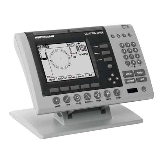
- Page 3 ND 1200 Introduction LCD screen Soft keys Measurement function keys Axis keys Mode selection keys Command keys Menu key Arrow cursor keys Fast track keys 10 Numeric keypad 11 Send key 12 LCD On/Off key ND 1200 panel keys Panel keys are used to initiate feature measurements, apply tolerances, send reports of measurement results and configure operational parameters.
- Page 4 Panel function key Panel key Menu key: Displays five soft key menus for system setup, programming, extra functions clearing data and optional optical edge detector functions. Arrow cursor keys: Used to scroll through lists and navigate menus and setup screen data fields. The up arrow cursor key is also used to begin a feature construction process, as described later in the feature Constructions portion of this chapter.
- Page 5 ND 1200 rear panel Serial number label Power switch Power cord connector and fuse holder Power ground access Measurement axis connectors RS-232 serial port connector Optical reference cable connector Optical sensor cable connector Not supported in the ND 1200 10 Tilt base mechanical tightness adjustment 11 Electrical Ratings label ND 1200 side panel Speaker/headset jack...
- Page 6 Information contained in this manual This User's manual covers the operation, installation, setup and specifications of the ND 1200. Operating information is contained in chapter 1. Installation, setup instructions and specifications are contained in chapter 2. Fonts used in this manual The following fonts are used to indicate operator controls or to show emphasis: Operator controls - soft keys and other panel keys are shown in...
-
Page 7: Safety Considerations
Safety considerations General accepted safety precautions must be followed when operating the system. Failure to observe these precautions could result in damage to the equipment, or injury to personnel. It is understood that safety rules within individual companies vary. If a conflict exists between the material contained in this manual and the rules of a company using this system, the more stringent rules should take precedence. - Page 8 Preface...
-
Page 9: Table Of Contents
1 Operation ..13 1.1 ND 1200 Overview ..14 1.2 Basic Functions of the ND 1200 ..16 Switching on the ND 1200 ..16 Establishing a repeatable machine zero ..17 Switching off the ND 1200 ..17 Panel key descriptions .. - Page 10 1.5 Creating Part Features ..47 Created features ..47 Creating features ..47 Example of creating a feature ..48 1.6 Constructing Part Features ..49 Constructed features ..49 Constructing features ..49 Example of constructing a feature ..50 ..
- Page 11 2 Installation, Setup and Specifications ..75 2.1 ND 1200 Shipment Contents ..76 Items included with the ND 1200 ..76 Optional items possibly included ..76 Repackaging the ND 1200 ..77 2.2 Hardware Installation ..78 Assembling the mounting stand ..78 Benchtop location and mounting ..
- Page 12 2.3 Software setup ..85 Setup menu ..86 Setup example: entering the supervisor password ..87 Order of setup ..88 Language selection and product version ..89 Supervisor password and program unlocking ..90 Loading settings files and startup screens ..91 Encoder configuration ..
-
Page 13: Operation
Operation... -
Page 14: 1.1 Nd 1200 Overview
1.1 ND 1200 Overview ® The ND 1200 is an advanced digital readout (DRO) system for performing high-precision 2, 3 or 4 axis measurements using analog or TTL encoders. The ND 1200 can be used with optical comparators, toolmaker’s microscopes or video measurement systems as part of in- line production or in final quality inspection. - Page 15 Number keypad with: Number keys for data entry Decimal point and +/- keys for data entry and LCD screen contrast adjustment User-defined hot keys that program panel and optional remote keys to initiate commonly used functions. User-defined programs made of the key-press sequences used to: Perform measurements Apply tolerances Report results...
-
Page 16: 1.2 Basic Functions Of The Nd 1200
1.2 Basic Functions of the ND 1200 Switching on the ND 1200 Switch on the ND 1200. The POWER switch is located on the rear of the enclosure. After switching the power on, or after a power failure, the power-up screen will be displayed. -
Page 17: Establishing A Repeatable Machine Zero
Establishing a repeatable machine zero If your ND 1200 was configured to establish a machine zero upon power-up, a message will be displayed asking you to cross reference marks or enter hard-stop axis reference positions. The machine zero is used by the ND 1200 to apply error correction data as measurements are performed. -
Page 18: Panel Key Descriptions
Panel key descriptions Descriptions of panel key functions are provided in the following pages for MEASUREMENT function, COMMAND, MODE selection, AXIS, FAST TRACK, SEND, LCD ON/OFF, and MENU keys. Soft key functions are also described later in the next section as part of screen and soft key layout descriptions. - Page 19 COMMAND keys Function Enter data: Press the ENTER key to enter points during feature measurements or to enter values into configuration fields. Pressing the ENTER key indicates that data from a measurement or in a field is ready for use. Finish a measurement: Press the FINISH key to complete a feature measurement.
- Page 20 FAST TRACK keys Function Left frequently used function: Press the left WIDE key to initiate the function programmed for this key. The factory default function for this key is ENTER. Right frequently used function: Press the right WIDE key to initiate the function programmed for this key.
- Page 21 ARROW CURSOR keys Function Navigate menus and setup screen data fields. The up arrow cursor key is also used to begin a feature construction process. ND 1200 QUADRA-CHEK...
-
Page 22: Lcd Screen And Soft Key Layout
LCD screen and soft key layout ND 1200 LCD screens display information in one of four operating modes: DRO mode displays current positions of axes Feature evaluation mode screens can be toggled between two displays that show all measurement results and the data cloud of collected points Feature measurement mode displays feature type, points collected and current positions of axes during measurements... -
Page 23: Feature Evaluation Mode Screens And Soft Keys
Feature evaluation mode screens and soft keys The feature evaluation screens can be toggled between two displays by pressing the VIEW soft key to show: Feature list of measured features on the left side Unit of measure, current datum and probe type in the upper right corner The feature type and number of the highlighted feature Feature position... -
Page 24: Feature Measurement Mode Screen And Soft Keys
Feature measurement mode screen and soft keys The feature measurement screen is displayed after initiating a feature measurement by pressing a MEASUREMENT key and shows: Feature list of measured features on the left side Unit of measure, current datum and probe type in the upper right corner The feature type being probed and the number of collected data points... -
Page 25: Nd 1200 Menus
ND 1200 Menus Press the MENU key to display menu titles over the soft keys at the bottom of the LCD screen. Press a menu soft key to display the corresponding menu screen. Menus include: SETUP menu SETUP functions Press the SETUP menu soft key to display the collection of SETUP screens used to configure... - Page 26 EXTRA menu EXTRA functions Press the EXTRA soft key to display the EXTRA pop- up menu. The EXTRA menu is used perform many measurement and data transmission functions. Highlight a function and then press the ENTER key. EXTRA menu functions include: Annot Toggles between forward and backward annotation.
- Page 27 EXTRA menu EXTRA functions Send F Sends current form error to a printer, USB drive or computer. Send L Sends current distance to a printer, USB drive or computer. Send Q Sends current Q-axis value to a printer, USB drive or computer.
- Page 28 CLEAR menu CLEAR functions Clr Ft Clears feature data from the feature list. Clr Sk Clears the part alignment (skew). Clearing the skew does not clear any datums that have been established. Clr All Clears feature, datum and part alignment data. EDGE menu EDGE functions Press the EDGE soft key to...
-
Page 29: 1.3 Preparing To Measure
1.3 Preparing to Measure Power-up the ND 1200 Switch on the ND 1200. The POWER switch is located on the rear of the enclosure. After switching the power on, or after a power failure, the power-up screen will be displayed. See "Switching on the ND 1200"... -
Page 30: Adjust Lcd Screen Contrast
Adjust LCD screen contrast If necessary, adjust the LCD screen contrast using the decimal point and +/- keys located on the numeric keypad. Press the DECIMAL POINT key to increase the contrast Press the +/- key to decrease the contrast Select unit of measure Press the UNIT OF MEASURE key to toggle between millimeters and inches. -
Page 31: Select The Desired Annotation
Select the desired annotation Annotation determines the number of measurement points collected for each feature type. Forward annotation: Use forward annotation to require a previously specified number of points for each feature type. When using forward annotation, the number of required points is shown in the top left corner of the screen. -
Page 32: Select A Probe Type
Select a probe type Features are probed with crosshairs or with optional optical edge detection. Optical edge detection can be configured as manual or automatic point entry. Skip these probe selection instructions if your ND 1200 does not include the optical edge detection option. Select crosshairs: Press the PROBE soft key if necessary to select the crosshair probe. -
Page 33: Calibrate The Optical Edge Detector
Calibrate the optical edge detector The optical edge detector must be calibrated to correctly recognize light to dark part edge transitions. Calibration should be performed after startup, when the part is changed, when magnification is changed, when measuring a part with fuzzy or irregular edges, and when the optical system is repositioned or replaced. -
Page 34: Align The Part To A Measurement Axis
Align the part to a measurement axis Accurate measurements require the part to be perfectly aligned along a measurement axis. Misaligned parts result in cosine measurement errors. Use the SKEW function to convert machine coordinates to part coordinates and compensate for part misalignment. Measure a skew each time a new part is mounted on the measuring system. -
Page 35: Establish A Datum
Establish a datum Establish a reference datum once the part is skewed. Two datums can be created in the ND 1200. Typically, datum 1 is a zero reference and used as an absolute or primary datum, while datum 2 is used as an incremental or temporary datum. -
Page 36: Construct A Datum Point From Line Features
Construct a datum point from line features Construct a point from the skew line and the left edge line to create a datum. Press the POINT key. The Probe Point screen will be displayed. Press UP ARROW/ENTER to start the construction and select the line feature (2). -
Page 37: Presetting The Datum
Presetting the datum Datums can be zeroed or preset. This example creates a preset reference datum from a point feature. With the datum point highlighted in the feature list, press the DATUM key if necessary to select the desired datum in the upper right corner of the screen. Press MENU/EXTRA/PRESET/ENTER to display the preset screen. -
Page 38: 1.4 Measuring Part Features
1.4 Measuring Part Features Part features Features are measured by probing data points that characterize the dimensional geometry of the part. For example, several points probed around the circumference of a circle results in numeric and graphic representations of the circle geometry. Throughout this manual, a measured geometry is referred to as a feature and can alternately be displayed numerically or graphically by pressing the VIEW soft key. -
Page 39: Probing Part Features
Probing part features Part features can be probed with crosshairs or with optional optical edge detection. If optical edge detection is used, points can be entered manually or automatically. Probing with crosshairs Move the stage to position the crosshairs over the desired feature point and press the ENTER key. -
Page 40: Probing With Measure Magic
Probing with Measure Magic Measure Magic analyzes feature data collected by part probing and automatically determines the feature type. Measure Magic supports the following feature types in the ND 1200: Points Lines Circles Distances Angles When Measure Magic is used, and more than the minimum number of points required to define a feature type are collected, the feature type can be changed manually by the user if the wrong feature type is assigned. -
Page 41: Measuring Features
Measuring features The ND 1200 measures point, line, circle, distance and angle features. To measure a feature using backward annotation (See "Select the desired annotation" on page 31): Press the desired feature MEASUREMENT key Probe the required points Press the FINISH key Auto repeat Use auto repeat to measure several features of the same type (such as a series of circles). -
Page 42: Measuring Points
Measuring points Points are the simplest features to measure. Only one point is required to define the location of a point. A maximum of 100 points can be probed and will be averaged by the system to measure a single point. Press the POINT MEASUREMENT key. -
Page 43: Measuring Lines
Measuring lines A minimum of 2 points are required to measure a line. A maximum of 100 points can be probed and will be processed by a fit algorithm to define the line. Press the LINE MEASUREMENT key. The Probe Line screen will be displayed. -
Page 44: Measuring Circles
Measuring circles A minimum of 3 points are required to measure a circle. A maximum of 100 points can be probed and will be processed by a fit algorithm to define the circle. Press the CIRCLE MEASUREMENT key. The Probe Circle screen will be displayed. -
Page 45: Measuring Distances
Measuring distances Two points are required to measure a distance. Press the DISTANCE MEASUREMENT key. The Probe Distance screen will be displayed. Press the key twice to measure a series of distances using auto repeat. Move the stage to position the crosshairs over the first of the two points, then and press the ENTER key. -
Page 46: Measuring Angles
Measuring angles A minimum of 4 points evenly divided on two legs of an angle are required to measure an angle. A maximum of 100 points can be probed on the two angle legs. Once the minimum two points are probed on each angle leg, additional points can be distributed between the two legs in any proportion. -
Page 47: 1.5 Creating Part Features
1.5 Creating Part Features Created features It can be useful to create features that are not found on the part geometry. Created features can be used as reference points for inspection purposes. For example, in order to measure a feature that is referred to a point off the part geometry, the user could create the reference point. -
Page 48: Example Of Creating A Feature
Example of creating a feature In this example, a circle is created: Press the feature MEASUREMENT key. In this example, the CIRCLE MEASUREMENT key is pressed and the Probe Circle screen is displayed. Press the CREATE soft key to display the Create data entry screen. -
Page 49: 1.6 Constructing Part Features
1.6 Constructing Part Features Constructed features New features can be constructed from probed, created, or other constructed features from the features list. Constructions are frequently used to perform skew alignments, set datums and measure relationships between parent features. Users can construct points, lines, circles, distances, angles, and part skews. -
Page 50: Example Of Constructing A Feature
Example of constructing a feature In this example, a new point feature is constructed from two parent circle features: Press the feature MEASUREMENT key corresponding to the feature you want to construct. In this example, the POINT MEASUREMENT key is pressed. Press the CONSTR soft key or press the up ARROW CURSOR key to highlight the last feature in the feature list. -
Page 51: More Feature Construction Examples
Press the VIEW key to show a graphic image of the feature construction. In this example the image shows that the Int 1 point feature was constructed at the top intersection of the two circle circumferences. Press the CHANGE soft key to show alternative point features that can be constructed from the two parent circle features. - Page 52 Construction Parent features Graphic Point Two points: mid point Point Point and circle: mid point Point Distance and point: offset Point Circle: center point Point Line and point: perpendicular Point Line and datum: perpendicular Line Points: Best fit Line Line and circle: perpendicular Line Two lines: bisector Line...
- Page 53 Construction Parent features Graphic Circle Multiple circles: best fit Circle Circle and distance: offset Distance Two points: point to point Distance Circle and circle: center to center Distance Point and line: perpendicular Angle Two lines: vertex ND 1200 QUADRA-CHEK...
-
Page 54: 1.7 Tolerancing
1.7 Tolerancing Feature tolerances The following tolerances are available in the ND 1200. Feature type Tolerance Point Bidirectional position Point True position Line Bidirectional position Line True position Line Straightness Line Perpendicularity Line Parallelism Line Angle Circle Bidirectional position Circle True position Circle LMC: Least material condition... -
Page 55: Applying Tolerances
Applying tolerances The method of applying tolerances is identical for all feature types. To apply a tolerance: Highlight a feature in the feature list using the ARROW CURSOR keys. Press the TOL soft key to display the tolerance soft keys. Press the soft key corresponding to the desired tolerance type, such as runout for a circle. -
Page 56: Example Of Applying A Tolerance
Example of applying a tolerance In this example, a form tolerance (roundness) is applied to a circle feature: Use the ARROW CURSOR keys to highlight the desired feature in the feature list. In this example, the circle feature is highlighted. Press the TOL soft key to display the tolerance alternatives above the soft keys at the bottom of the screen. - Page 57 Enter the desired nominal and tolerance values into the data fields provided. In this example of circle form tolerance, only the roundness tolerance field is provided, and a tolerance of 0.15 is entered. Press the FINISH key to display the tolerance result. The tolerance and actual values will be displayed.
-
Page 58: 1.8 Programming
1.8 Programming ND 1200 programs ND 1200 programs automate repetitive measurement and inspection tasks. Programs are recorded sequences of measurement and other operator key-press activities stored in the ND 1200 to be played back later when inspecting identical parts. Any key-press activity can be included. -
Page 59: Example Of Recording A Program
Example of recording a program In this example, a program is created to measure several features on the 2-D demo part: Press the MENU soft key to display the menu soft key titles at the bottom of the screen. Press the PROG soft key to display the Programs screen. Press the RECORD soft key to initiate the recording process and display the program number dialog box. -
Page 60: Running A Program
Running a program To run (play back) a ND 1200 program: Press the MENU key. Press the PROG soft key. The Program screen will be displayed. Use the ARROW CURSOR keys to highlight the desired program number. Press the RUN soft key. The DRO screen will be displayed and the program will begin running. -
Page 61: Example Of Running A Program
Example of running a program In this example, the program recorded in the earlier example of recording a program is run: Press the MENU soft key to display the menu soft key titles at the bottom of the screen. Press the PROG soft key to display the Programs screen. Highlight the desired program number using the ARROW CURSOR keys. -
Page 62: Editing A Program
Editing a program Programs can be edited to change, insert, or delete program steps. There are a variety of reasons to edit programs. A program may contain an error or omission. For example, a feature may have been left out or measured using the wrong reference. Part specifications might change and editing an existing program is often faster than creating a new program. -
Page 63: Expanding And Compressing A Program Steps
Expanding and compressing a program steps To expand or compress a program step: Use the ARROW CURSOR keys to highlight a compressed step. Compressed steps are indicated by a + sign in a box in front of the step. Press the ENTER key to toggle between expanding and compressing the step. -
Page 64: Changing A Program Step
Changing a program step Program steps can be edited to change: Program properties Settings Tolerances To change program steps: Use the ARROW CURSOR keys to highlight a step. Expand the step if necessary. Press the ENTER key to cycle through the available alternatives and select a new value for the highlighted the step. - Page 65 Example of changing program properties In this example, program properties will be edited to change the behavior of the program when a tolerance fails. Initially, the program pauses when a tolerance fails; after the change, the program will not pause: To change program properties: Use the ARROW CURSOR keys to highlight the Prg Properties step.
- Page 66 Example of changing tolerances In this example, a roundness form tolerance will be edited to be more forgiving: To change a tolerance: Use the ARROW CURSOR keys to highlight the Circle measurement step. Press the TOL key to display the circle tolerance screen. Highlight the desired data field if necessary.
-
Page 67: Deleting A Program Step
Deleting a program step Program steps can be deleted to simplify programs or to remove unwanted steps. Any program step can be deleted, including program property and ND 1200 settings steps. Use care when deleting program steps, and store a backup of the program first. -
Page 68: Inserting New Program Steps
Inserting new program steps Program steps can be inserted to update programs to accommodate part changes or to correct omissions. To insert new steps: Use the ARROW CURSOR keys to highlight the desired insertion point for the new steps. The new steps will be inserted before, not after, the insertion point. -
Page 69: Copying A Program
Copying a program When similar parts will be measured, it is often quicker to copy an existing program and edit it to accommodate the new part than to record a new program from the beginning. To copy a program: Press the MENU soft key to display the menu soft key titles at the bottom of the screen. -
Page 70: Deleting A Program
Deleting a program When programs are no longer needed, they can be deleted to conserve resources. To delete a program: Press the MENU soft key to display the menu soft key titles at the bottom of the screen. Press the PROG soft key to display the Programs screen. Highlight the desired program number using the ARROW CURSOR keys. -
Page 71: Backing Up Programs
Backing up programs Programs can be backed up prior to editing or deleting them by saving them with the ND 1200 settings file. Backup and restore procedures should only be performed by supervisors and other technically qualified personnel. Program files are included with ND 1200 settings files. Settings files often include error correction calibration data and care must be taken to avoid using obsolete or outdated files. -
Page 72: 1.9 Reporting
1.9 Reporting Reporting Reports of measurement results can be sent to a USB printer or USB flash drive over the USB port, or to a PC over the RS-232 serial port. Report content, destination and format are specified in the Print, RS-232 and USB setup screens discussed in Chapter 2: Installation and Specifications. -
Page 73: 1.10 Error Indications
1.10 Error Indications Scale errors Only input encoder scale errors are reported by the ND 1200. Scale errors are indicated by the presence of graphic bars across the DRO screen instead of numbers. Scale errors can be caused by a few conditions shown in this table: Possible cause Corrective action... - Page 74 1 Operation...
-
Page 75: Installation, Setup And Specifications
Installation, Setup and Specifications... -
Page 76: 2.1 Nd 1200 Shipment Contents
2.1 ND 1200 Shipment Contents The contents of your ND 1200 shipment are described below. Repackaging instructions are also included for return shipments for distributors and OEM customers that are configuring a ND 1200 and shipping it to an end-user. Save the ND 1200 packaging materials for possible return shipment or shipment to an end-user. -
Page 77: Repackaging The Nd 1200
Repackaging the ND 1200 When shipping the ND 1200 on to an end-user, repackage all ND 1200 components in the original packaging as received from the factory. The original packaging must be duplicated and the LCD must be inserted face-up to prevent damage to the screen. -
Page 78: 2.2 Hardware Installation
2.2 Hardware Installation The ND 1200 is easy to install in a variety of measurement applications. This section describes how to install the ND 1200 hardware. Assembling the mounting stand The ND 1200 is secured to the swivel slots of the mounting stand by a shoulder screw, a cap screw and associated washers. -
Page 79: Arm Mounting (Optional)
Arm mounting (optional) Secure the arm mount adapter to the ND 1200 and bolt the adapter and ND 1200 to the arm as shown at the right. Optional arm mounting ND 1200 QUADRA-CHEK... -
Page 80: Connecting Power
Connecting power Connect the ND 1200 to power through a high-quality power surge suppressor. Surge suppressors limit the amplitude of potentially damaging power line transients caused by electrical machinery or lightning, and protect the ND 1200 from most power line transients that can corrupt system memory or damage circuits. -
Page 81: Connecting Encoders
Connecting encoders Axis encoders are attached to interface connectors on the rear of the ND 1200. Many encoder interfaces are available to match the wide variety of encoders that can be used with the ND 1200. The type and number of axis encoder connectors will vary depending on the application. -
Page 82: Connecting A Computer
Connecting a computer Measurement result data can be sent to a computer over the RS-232 port (3) using a serial cable that does not include crossed wires. To connect a computer: Verify that the ND 1200 and the computer power are off. Connect a computer COM port to the ND 1200 RS-232 serial port (3) using a standard straight-through serial cable (Metronics part number 11B12176). -
Page 83: Connecting An Optional Foot Switch Or Remote Keypad
Connecting an optional foot switch or remote keypad The optional foot switch and remote keypad are connected to the RJ-45 connector on the side of the ND 1200. Often, only the optional foot switch or remote keypad is used. However, two options can be connected simultaneously using a RJ-45 splitter. -
Page 84: Connecting And Installing Optical Edge Detection
Connecting and installing optical edge detection The optical edge detection option reference and sensor cables are connected to two cable jacks on the rear of the ND 1200. The optical cable jacks are shown here: Reference cable input Sensor cable input The reference cable is connected to the light reference source. -
Page 85: 2.3 Software Setup
2.3 Software setup The operating parameters of the ND 1200 must be configured prior to using it for the first time, and any time part measurement, reporting or communication requirements change. Day to day use of the ND 1200 does not require reconfiguration of software settings. Parameter changes made in any of the setup screens can change the operation of the ND 1200. -
Page 86: Setup Menu
Setup menu Most operating parameters of the ND 1200 are configured using screens and data fields accessed from the setup menu. Highlighting setup menu items on the left side of the setup screen displays the corresponding setup parameter data fields and choice fields on the right side of the screen. -
Page 87: Setup Example: Entering The Supervisor Password
Setup example: entering the supervisor password Critical setup parameters are password-protected. Only qualified personnel should be given password access to setup screen parameters. In this example, the setup menu is navigated to the Supervisor screen and the supervisor password is entered. To enter the supervisor password: Press the MENU key to display the menu soft keys. -
Page 88: Order Of Setup
Order of setup The ND 1200 setup software is contained on up to 18 screens, depending on the hardware configuration. It is possible that not all the setup screens described in this chapter are active in your system. Disregard screen descriptions that do not apply to your ND 1200. The initial ND 1200 setup tasks should be performed in the order listed here. -
Page 89: Language Selection And Product Version
Language selection and product version The About screen contains selections for changing the language of text displayed on the screen, included in transmitted data and printed on reports. Product software and hardware information is also provided on the About screen. The product software and hardware version information will be required if technical support is required. -
Page 90: Supervisor Password And Program Unlocking
Supervisor password and program unlocking The Supervisor screen contains the Password data field and Programs Locking choice field. Most setup parameters are password-protected and setup can only be performed after the password is entered. To enter the supervisor password: Press MENU/SETUP to display the setup menu and then highlight the Supervisor menu item. -
Page 91: Loading Settings Files And Startup Screens
Loading settings files and startup screens The Supervisor screen contains tools for loading ND 1200 configuration settings files and OEM startup screens. Settings files can be loaded from a USB drive when the configuration parameters from a previous setup session were saved. This eliminates the need to configure the ND 1200 manually using the setup screens. -
Page 92: Encoder Configuration
Encoder configuration The Encoders and Misc screens contain data and choice fields for configuring the encoders. Encoders screen The Encoders screen configuration fields include: Axis selection Encoder resolution Encoder type TTL or analog) Reference mark selection Machine zero offset (MZ Cnts) Reversing encoder count direction Units of measure To configure encoder settings in the Encoders screen:... - Page 93 Highlight the Type choice field and then press a soft key to select the encoder type. Highlight the Ref Marks choice field and then press the LIST soft key to display the reference mark choices. Highlight the required encoder reference mark type and press the ENTER key. Reference marks must be used if SLEC or NLEC error correction will be performed later.
- Page 94 Highlight the Reversed choice field and then press the YES soft key to reverse the encoder count direction. Highlight the Units choice field and then press the IN or MM soft key for inch or millimeter units of measure. Choose a count direction Choose a unit of measure Press the FINISH key to save parameters and return to the setup menu.
-
Page 95: Misc Screen
Misc screen The Misc screen encoder configuration fields include: Auto DRO counts: The number of least significant DRO counts required to refresh the DRO with new axis values. External axis-zero enable for X, Y, Z and Q axes. Allows axes to be zeroed remotely from encoder zero buttons. -
Page 96: Optical Edge Detection Setup
Optical edge detection setup The Edge menu and Misc setup screen contain fields and other tools for configuring optical edge detection. Edge menu tools The Edge menu contains tools for installing and calibrating optical edge detection. To install optical edge detection: Turn the ND 1200 and the comparator on to check the optical light levels. -
Page 97: Misc Screen
Misc screen The Misc screen contains fields for configuring: Optical edge (OE) time-out: The minimum allowed time in milliseconds between the detection of two edges. This time is specified to prevent noise from being recognized as valid edges. Optical edge (OE) debounce: The minimum time in milliseconds that a light transition must be stable to result in a valid edge detection. -
Page 98: Stage Squareness Calibration
Stage squareness calibration The Squareness screen contains data and choice fields for calibrating the squareness of the measuring system. The calibration of stage squareness requires the use of a certified square artifact. Squareness calibration is unnecessary if optional NLEC error correction will be used. Error correction is discussed later in this chapter. -
Page 99: Error Correction
Error correction There are three error correction methods used by the ND 1200: LEC: Linear Error Correction SLEC: Segmented Linear Error Correction NLEC: Nonlinear Error Correction All ND 1200 models are equipped with LEC, SLEC and NLEC. Each method compensates for encoder and machine travel variations with error correction coefficients. -
Page 100: Linear Error Correction (Lec)
Linear error correction (LEC) LEC compensates for machine irregularities and encoder non- linearities by applying a single linear correction value to the entire range of measurement. To apply LEC to a measurement axis: Verify that the crosshair probe is selected. Press the PROBE soft key to select it if necessary. - Page 101 Perform a single measurement of the entire range of motion using the standard artifact and make a note of the result. Use an artifact that allows measurements of as much of the axis range of motion as possible. In this example of applying LEC, one point at end of the axis measurement range is measured using an 8 inch standard.
-
Page 102: Segmented Linear Error Correction (Slec)
Segmented linear error correction (SLEC) SLEC compensates for machine irregularities and encoder non- linearities by applying correction values to individual segments that cover the entire range of motion along an axis. To apply SLEC to a measurement axis: Verify that the crosshair probe is selected. Press the PROBE soft key to select it if necessary. - Page 103 Verify that values in the LEC screen are Verify that NLEC (optional) Verify that the SLEC enable is OFF all 1.000 compensation is OFF Press MENU/CLEAR/CLR ALL to clear all existing datums, part alignments and part data. Position the standard artifact along the measurement axis. Align the artifact as closely as possible to the axis and then perform a skew alignment as described in chapter 1 (see "Align the part to a measurement axis"...
- Page 104 To configure segmented linear error correction in the SLEC screen: Position the crosshair probe is over the zero reference of the standard artifact and press the AXIS key to zero the axis at the zero position of the standard. Highlight the SLEC menu item. Highlight the Axis choice field and select the axis for correction.
- Page 105 Highlight the Standard field and enter the Standard value at the end of segment 3. In the example, the value is 3.00000. Then highlight the Observed field and press the TEACH soft key. The system will enter the value measured at the end of the segment. In the example the Observed value at Station 3 is 2.98000.
-
Page 106: Nonlinear Error Correction (Nlec)
Nonlinear error correction (NLEC) NLEC minimizes or eliminates the small inaccuracies in the X-Y measurement plane due to machine irregularities and encoder nonlinearity. Error correction coefficients are obtained by measuring a certified calibration grid. The actual values are then compared to the nominal grid values by the ND 1200. - Page 107 Highlight the SLEC setup menu item (if NLEC is present) and verify that the Enabled choice field specifies OFF. NLEC can not be performed if a different error correction is already enabled. NLEC correction can not be configured while NLEC is enabled. Highlight the NLEC setup menu item and verify that the NLEC choice field specifies OFF.
-
Page 108: Nlec By Measuring Points On A Calibration Grid
NLEC by measuring points on a calibration grid Position the standard artifact along the measurement axis. Align the artifact as closely as possible to the axis and then perform a skew alignment as described in chapter 1 (see "Align the part to a measurement axis"... - Page 109 Grid measurement locations are Nominal and actual grid values are Press the ON soft key to enable NLEC indicated in the top left corner of the displayed when the calibration is screen. complete Highlight the NLEC choice field and press the ON soft key to enable NLEC correction.
-
Page 110: Nlec By Importing An Nlec.txt File
NLEC by importing an nlec.txt file An nlec.txt file created by measuring a certified calibration grid with a IK 5000, ND 1300 or ND 1200 can be used to provide NLEC correction data instead of measuring a calibration grid with the target ND 1200 system. -
Page 111: Measurement Scaling For Parts That Expand Or Shrink
Measurement scaling for parts that expand or shrink Scale factors scale measurement results using a multiplier and are useful when measuring parts that will expand or shrink after inspections have been performed. Scale Factor screen The Scale Factor screen contains configuration fields for: Enabling scale factor Specifying a scale factor multiplier value Providing the user access to scale factor editing... -
Page 112: Measurement Configuration
Measurement configuration The Measure screen contains data and choice fields for configuring ND 1200 measurement parameters. Measure screen The Measure screen contains configuration fields for: Specifying forward or backward annotation point probing Retaining features across power cycles Specifying absolute or signed distances Requiring a machine zero upon startup Specifying a probing targeting zone size for programs that utilize optical edge detection... - Page 113 Highlight the Retain features choice field and then press the YES soft key to retain features in the feature list across power cycles. Press the NO soft key if discarding features when the power is turned off is preferred. Highlight the Distances choice field and press the SIGNED soft key to display + and - distances.
- Page 114 Highlight the Targeting zone data field and enter the target box size displayed when running a program that uses optical edge detection for part probing. Points outside the target zone box will not be recognized when the program is running. Highlight the Pause Tol Results choice field and press the desired soft key to pause program execution in response to tolerance tests: Soft key...
-
Page 115: Display Formatting
Display formatting The Display screen contains data and choice fields for configuring display resolution and other display parameters. Display screen The Display screen configuration fields include: Resolutions for linear and angular measurements Startup linear and angular units of measure Selection of a comma or decimal point radix Unit of angular measurement for the current session Angular display resolutions for the Q-axis Range of displayed angles for angular measurements... - Page 116 Highlight the Startup Linear choice field and press a soft key to specify a unit of linear measure set by the ND 1200 upon startup. Soft key selections are: Soft key Result The linear unit of measure will be millimeters Inch The linear unit of measure will be inches Last...
- Page 117 Highlight the Current Angular choice field and press a soft key to set the current session to Decimal Degrees (DD), or Degrees/Minutes/ Seconds (DMS). Highlight the Q DMS and Q DD Res data fields and enter the display resolution index numbers for each of the angular units of measure. The Q DMS and Q DD Disp Res fields configure the protractor readings shown on the DRO.
-
Page 118: Hot Key Assignments
Hot key assignments The Hot Keys setup screen is used to map frequently used functions to front panel keys, remote keypad keys and foot switch keys. Hot keys can save time by eliminating the need to navigate through menus to initiate a function, or by making a function more accessible through a foot switch or remote keypad. - Page 119 To assign a function to a hot key: Press MENU/SETUP to display the setup menu and then highlight the Hot keys menu item. Highlight the Keys choice field and then press a soft key to select the desired key type or switch type. In this example the Foot switch type is selected.
- Page 120 The functions contained in the Special menu are shown here: The selection of a language can be assigned to a hot key. Individual languages appear in the Special menu but are not shown separately in this list of hot key functions. Special menu function Description Annot...
- Page 121 Special menu function Description Teach Initiates an (optional) optical edge calibration Time Displays the current time and date Zero 2 Zeroes the X and Y axes Zero Q Zeroes the Q-axis Languages Selects a language ND 1200 QUADRA-CHEK...
-
Page 122: Print Formatting
Print formatting Print formatting data and choice fields are contained in the Print and Form Characters screens. Print screen The Print screen configuration fields include: Report width in characters Report length in lines per page Form feed Printer control characters before and after lines and after forms Automatic labeling of report data Printing reports when (optional) optical edges are crossed Including units of measure in reports... - Page 123 Highlight the Pre Line, Post Line or Post Form data field and then enter the desired ASCII character. Up to four ASCII key codes can be entered for each data field. For example, Ascii key codes entered in the Pre Line field occur before each line of print on a report, so entering an ASCII key code 32 inserts a space before each line of print.
- Page 124 ASCII codes: Code Character Code Character Code Character Code Character Code Character Backspace Horizontal tab Space Line feed Vertical tab “ Form feed Carriage return < & ‘ > ‘ 2 Installation and Specifications...
-
Page 125: Form Chars Screen
Highlight the Print Units choice field and press the YES soft key to include unit of measure labels with the printed data. Press the YES soft key to include units of measure Press the finish key to return to the setup menu. Form chars screen The Form chars (characters) screen contains printer configuration data fields for including ASCII control strings in front of the report data... -
Page 126: Rs-232 Port Configuration
RS-232 port configuration The RS232 screen contains data and choice fields for configuring communication parameters of the RS-232 serial port. RS232 screen The RS232 screen configuration fields include: Baud rate Word length Stop bits Parity Type of data sent on the serial port End of character and end of line delay To configure the RS-232 port: Press MENU/SETUP to display the setup menu and then highlight... - Page 127 Highlight the Parity choice field and press a soft key to select ODD, EVEN or NONE. Highlight the Data choice field and press the LIST soft key to display the data choices for communication on the RS-232 port. Highlight the data choice and press the ENTER key to select the data.
-
Page 128: Usb Port Configuration
USB port configuration The USB port can send data to a flash drive on the USB port or to a USB printer. The USB screen contains data and choice fields for configuring communication parameters of the USB port. USB screen The USB screen configuration fields include: Type of data sent on the USB port Destination of the data;... - Page 129 Highlight the Destination choice field and press the HP2 soft key to select a printer or the FILE soft key to send data to a file on the USB drive. Highlight the File Type choice field and press a soft key to select one of the following file types: Replace: The existing file is replaced each time a file is sent Append: The existing file is extended to include the new data...
-
Page 130: Audio Configuration
Audio configuration The ND 1200 can be configured to generate a sound in response to certain measurement activities and results. Sounds screen The Sounds screen contains choice fields for enabling or disabling audio beeps in response to: Warning: Any warning shown on the screen Point entry: When a point is entered during measurement Begin measure: Immediately prior to a measurement during a program execution... -
Page 131: Key Repeat Rate Adjustment
Key repeat rate adjustment When a front panel key is pressed and held, the function repeats. The auto-repeat rate for front panel keys can be adjusted. Misc screen The Misc screen contains a data field for adjusting key repeat rate. To adjust the key repeat rate: Press MENU/SETUP to display the setup menu and then highlight the Misc menu item. -
Page 132: Time And Date Settings
Time and date settings The time and date appear in data, on reports and can be displayed on the screen through the Extra menu. Clock screen The Clock screen contains data fields for setting the time and date. To set the time and date: Press MENU/SETUP to display the setup menu and then highlight the Clock menu item. -
Page 133: Saving Settings Files And Programs
Saving settings files and programs The Supervisor screen contains tools for saving ND 1200 configuration settings files which include any ND 1200 programs and error correction data. Settings files are saved to the root of a USB drive. Settings files should be saved any time configuration changes are made, error correction data is collected or programs are created or modified. -
Page 134: 2.4 Specifications
2.4 Specifications Specifications Axes 2 to 4 axes Encoder inputs Linear and rotary encoders Analog 1 V Display Black and white LCD 5.7” (14.48 cm) 0.50” (1.27 cm) display digit size 0.000004” (0.00001 mm) Resolution Error compensation Linear (LEC), segmented linear (SLEC, Nonlinear (NLEC) Data interfaces Serial interfaces RS-232-C... -
Page 135: Dimensions
Dimensions The ND 1200 enclosure, tray stand and arm mount bracket dimensions are shown in the format: mm. ND 1200 QUADRA-CHEK... -
Page 136: Arm Mount Bracket
Arm mount bracket 2 Installation and Specifications... - Page 137 NUMERICS Comparator screen ... 84 Error correction ... 29 Computer ... 82 Linear error correction (LEC) ... 99, 2-wire power plug adapters ... 7 Constructing part features ... 49 3-wire grounded outlet ... 7 Example ... 50 NLEC by importing an nlec.txt More examples ...
- Page 138 Measure screen ... 112 Prog ... 25 Measuring part features ... 38 Copy ... 25 Hard-stop axis reference position ... 17 Angles ... 46 Delete ... 25 Hardware installation ... 78 Auto repeat ... 41 Edit ... 25 Arm mounting ... 79 Circles ...
- Page 139 Probe type ... 32 Reversing encoder count direction ... 92 Software setup ... 85 Crosshairs ... 32 RJ-45 connector ... 83 Audio configuration ... 130 Optical edge ... 32 RJ-45 splitter ... 83 Display formatting ... 115 Manual and automatic point RS232 screen ...
- Page 140 Teach soft key ... 105 Time ... 132 Tolerancing ... 54 Applying tolerances ... 55 Example ... 56 Feature tolerances ... 54 Print report based on tolerance result ... 112 Unit of measure selection ... 30 Units of measure ... 92 USB flash drive ...
- Page 141 682 110-20 · Ver00 · SW2.16 · pdf · 4/2009...
Need help?
Do you have a question about the ND 1200 - V2.16 and is the answer not in the manual?
Questions and answers