Siemens SITRANS FC410 Operating Instructions Manual
Coriolis flowmeters with modbus
Hide thumbs
Also See for SITRANS FC410:
- Demo software user notes (21 pages) ,
- Quick start manual (94 pages)

Related Manuals for Siemens SITRANS FC410


Summary of Contents for Siemens SITRANS FC410
- Page 1 SITRANS F Coriolis flowmeters SITRANS FC410 with Modbus Operating Instructions Edition 02/2016 Answers for industry.
- Page 3 Spare parts and accessories Dimensions and weight Modbus holding registers Sensor dimension dependent default settings Zero point adjustment CRC calculation Exception codes Float definition These Operating Instructions apply to Siemens product SITRANS FC410 with order codes commencing 7ME4611, 7ME4621 and 7ME4711. 02/2016 A5E33120874-AC...
- Page 4 Note the following: WARNING Siemens products may only be used for the applications described in the catalog and in the relevant technical documentation. If products and components from other manufacturers are used, these must be recommended or approved by Siemens. Proper transport, storage, installation, assembly, commissioning, operation and maintenance are required to ensure that the products operate safely and without any problems.
-
Page 5: Table Of Contents
Table of contents Introduction ............................. 7 History ............................7 Items supplied ........................... 8 Checking the consignment ....................... 8 Device identification ........................9 Further Information ......................... 14 Safety notes ............................15 Laws and directives ........................ 15 Installation in hazardous locations ..................16 Certificates .......................... - Page 6 Table of contents Commissioning ............................. 51 General requirements ......................51 Warnings ..........................51 Operating via SIMATIC PDM ....................51 Functions in SIMATIC PDM ....................52 Commissioning steps ......................52 Initial setup ..........................52 Adding device to communication network ................54 Configuring a new device .......................
- Page 7 Table of contents Troubleshooting/FAQs .......................... 85 10.1 Diagnosing with PDM......................85 10.2 Troubleshooting ........................85 Technical data ............................91 11.1 Function and system design ....................91 11.2 Process variables ........................91 11.3 Modbus Communication Specification ..................92 11.4 Performance ........................... 93 11.5 Rated operating conditions .....................
- Page 8 Table of contents A.3.5 Maintenance & Diagnostics ....................128 A.3.6 Communication ........................132 A.3.7 Characteristics ........................133 A.3.8 Simulation ..........................135 A.3.9 Alarms ..........................136 A.3.10 Quality codes for process values ..................138 Sensor dimension dependent default settings ..................139 Zero point adjustment ..........................
-
Page 9: Introduction
The sales contract contains all obligations on the part of Siemens as well as the complete and solely applicable warranty conditions. Any statements regarding device versions described in the manual do not create new warranties or modify the existing warranty. -
Page 10: Items Supplied
Introduction 1.2 Items supplied Items supplied With M12 plug connection • SITRANS FC410 flowmeter • Sensor cable with M12 connector • SD card with production certificates • Quick Start guide • CD containing software, certificates and device manuals With sensor terminal housing •... -
Page 11: Device Identification
Introduction 1.4 Device identification 3. Retain damaged parts for clarification. 4. Check the scope of delivery by comparing your order to the shipping documents for correctness and completeness. WARNING Using a damaged or incomplete device Danger of explosion in hazardous areas. •... - Page 12 The flowmeter serial number is constructed as follows: PPPYMDDxxxxxx where PPP = Production factory (Siemens Flow Instruments: FDK) Y = Production year (for encryption, see below) M = Production month (for encryption, see below) DD = Production date (for encryption, see below)
- Page 13 Introduction 1.4 Device identification October November December Date (DD) Code Day 1 to 31 01 to 31 (corresponding to the actual date) FC410 sensor specification nameplate ① EX approvals Ex approval specifications for the sensor (ATEX example) ② Consult the operating instructions ③...
- Page 14 ⑧ Firmware version Image 1-3 FC410 Mini Flow Link identification nameplate Note Approval identifications Approval certificates and notified body identifications are available for download at siemens.com FC410 sensor approval nameplate ① QR code Product-specific QR code ② C✓ C-tick logo ③...
- Page 15 Introduction 1.4 Device identification Note Logos and warnings Logos and warnings are only shown on the product where applicable. The combination shown in the example above is relevant for a hygienic sensor. The Australian C-tick mark is mandatory on all products. FC410 EHEDG nameplate Image 1-5 EHEDG nameplate...
-
Page 16: Further Information
Product information on the Internet The Operating Instructions are available on the documentation disk shipped with the device, and on the Internet on the Siemens homepage, where further information on the range of SITRANS F flowmeters may also be found: Product information on the internet (http://www.siemens.com/flow) -
Page 17: Safety Notes
Safety notes This device left the factory in good working condition. In order to maintain this status and to ensure safe operation of the device, observe these instructions and all the specifications relevant to safety. Observe the information and symbols on the device. Do not remove any information or symbols from the device. -
Page 18: Installation In Hazardous Locations
Safety notes 2.2 Installation in hazardous locations Atmosphère explosible Directive of the European Parliament and the Council on the ATEX approximation of the laws of the Member States concerning 94/9/EC equipment and protective systems intended for use in potential- ly explosive atmospheres. Pressure equipment directi- Directive of the European Parliament and of the Council on the ve PED... - Page 19 Safety notes 2.2 Installation in hazardous locations Hazardous location approvals The device is approved for use in hazardous locations and has the approvals listed below. Special conditions for safe installation and operation specified by each approval authority are included in the relevant certificate. ATEX: FC410 flowmeter (can be installed in Zone 1 for gas and Zone 20/21 for dust): Certificate: SIRA 11ATEX1341X...
- Page 20 Safety notes 2.2 Installation in hazardous locations Sensor with Mini Flow Link (MFL) (FC410): Class I, II, III Division 1 Groups A, B,C, D, E, F, G Class I Zone1 and Zone 20/21 Note Control drawing See Control drawing: A5E31205486A Maximum temperature specifications for Ex use Device temperature classification with and without dust is related to the process temperature and ambient temperature as listed below.
- Page 21 ● EN/IEC 60079-14 is considered for installation in hazardous areas. Further information and instructions including approval-specific special conditions for safe use in Ex applications can be found in the certificates on the accompanying literature CD and at www.siemens.com/FC410 (www.siemens.com/FC410). WARNING Laying of cables...
-
Page 22: Certificates
2.3 Certificates Certificates Certificates are posted on the online support portal (http://www.siemens.com/processinstrumentation/certificates and can also be found on the documentation disk shipped with the device. Certification documents including calibration report are supplied with each sensor included on the SensorFlash. Material, pressure test, and factory conformance certificates are optional at ordering. -
Page 23: Description
Description Measurement of liquids and gases SITRANS F C Coriolis mass flowmeters are designed for measurement of a variety of liquids and gases. The flowmeters are multi-parameter devices offering accurate measurement of massflow, volumeflow, density, temperature and, depending on product variants, fraction, including industry-specific fractions. -
Page 24: Design
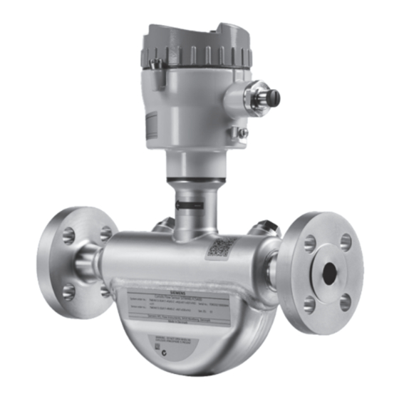
Description 3.1 Design Design The SITRANS FC410 flowmeter uses the Coriolis principle to measure flow. The device is a one channel flowmeter with Modbus RTU RS 485 output. Image 3-1 Flowmeter - M12 connection Image 3-2 Flowmeter – terminated cable... -
Page 25: System Integration
Description 3.2 System integration Flowmeter overview ① Mini Flow Link (MFL) ② Lid-lock ③ Cable feed-through (M12 socket or gland) ④ Plug and threaded port for example for pressure guard ⑤ Sensor enclosure ⑥ Process connections Image 3-3 Overview of FC410 flowmeter System integration The FC410 flowmeter functions as a Modbus RTU slave with standard Modbus commands implemented. - Page 26 Description 3.3 Modbus RTU technology Features The SITRANS F Modbus RTU communication complies with the Modbus Serial Line Protocol. Among other things this implies a master / slave protocol at level 2 of the OSI model. A node (the master) issues explicit commands to one of the slave nodes and processes responses.
-
Page 27: Features
Description 3.4 Features Features ● The SITRANS FC410 can be used as Modbus slave in stand-alone or parallel operation on Modbus or third party automation systems ● Compact sensor design ● NAMUR conforming sensor built-in lengths (on request) ● High immunity against process noise ●... - Page 28 Description 3.5 Theory of operation When the media flows through the sensor, Coriolis force will act on the measuring tubes and cause deflection which can be measured as a phase shift between Pickup 1 and Pickup 2. The phase shift is proportional to the mass flowrate. The frequency (or period) of the vibration is a direct function of the process media density.
-
Page 29: Installing/Mounting
Installing/Mounting SITRANS F flowmeters with minimum IP67/NEMA 4X enclosure rating are suitable for indoor and outdoor installations. ● Make sure that specifications for rated process pressure (PS) and media temperature (TS) plus ambient temperature that are indicated on the device nameplate / label will not be exceeded. -
Page 30: Determining A Location
Refer to the information in "Technical data" (Page 99). Note Material compatibility Siemens can provide you with support concerning selection of sensor components wetted by process media. However, you are responsible for the selection of components. Siemens accepts no liability for faults or failures resulting from incompatible materials. -
Page 31: Orientation Of The Device
Installing/Mounting 4.1 Flowmeter installation Upstream / downstream ● No pipe run requirements, that is straight inlet/outlet sections are not necessary. ● Avoid long drop lines downstream from the sensor to prevent process media separation causing air / vapour bubbles in the tube (min. back pressure: 0.2 Bar). ●... - Page 32 Orienting the sensor The sensor operates in any orientation. The optimal orientation depends on the process fluid and the process conditions. Siemens recommends orienting the sensor in one of the following ways: 1. Vertical installation with an upwards flow (self-draining)
- Page 33 Installing/Mounting 4.1 Flowmeter installation 3. Horizontal installation, tubes up (recommended for gas applications) Image 4-5 Horizontal orientation; tubes up Note Hygienic applications In 3A and EHEDG certified hygienic applications the flowmeter must be installed vertically as shown in 1 above. Installation in a drop line Installation in a drop line is only recommended if a pipeline reduction or orifice with a smaller cross-section can be installed to create back-pressure and prevent the sensor from being...
-
Page 34: Mounting The Flowmeter
Installing/Mounting 4.1 Flowmeter installation 4.1.4 Mounting the flowmeter NOTICE Incorrect mounting The device can be damaged, destroyed, or its functionality impaired through improper mounting. • Before installing ensure there is no visible damage to the device. • Make sure that process connectors are clean, and suitable gaskets and glands are used. - Page 35 Installing/Mounting 4.1 Flowmeter installation Avoid vibrations ● Make sure that no valves or pumps upstream of the flowmeter cavitates or sends vibration into the sensor. ● Decouple vibrating pipeline from the flowmeter using flexible tube or couplings Image 4-7 Non-flexible pipes not recommended in vibrating environment Image 4-8 Flexible pipes recommended in vibrating environment Avoid cross talk...
-
Page 36: Hydrostatic Testing
Pressure guard selection Siemens does not supply the components of the pressure guard solution because the arrangement and components are closely related to individual safety and protection practices in each place. - Page 37 Installing/Mounting 4.1 Flowmeter installation The selection of pressure guard solution is the responsibility of the user, however Siemens recommends the following forms of pressure guard: ● A pressure switch screwed directly or piped into one of the purge ports and connected to an automatic shut-off valve will disable pressurized supply to the meter.
- Page 38 Installing/Mounting 4.1 Flowmeter installation 4. Make sure that the pressure guard does NOT touch any of the parts inside the sensor. Maximum of 20 mm (0.79") insertion can be accommodated. 5. Check that the pressure guard has been correctly mounted and thoroughly tightened (torque: 80 Nm).
-
Page 39: Connecting
It is recommended to use cables supplied by Siemens A/S, Flow Instruments. ● Siemens supplied cables can be ordered with M12 plug on both ends or without plug. ● To guarantee the IP67 degree of protection, ensure that both ends of the cables are given equivalent protection from ingress of moisture. -
Page 40: Safety Notes For Connecting
Connecting 5.3 Safety notes for connecting See also specifications of cable lengths in Wiring FC410 to the Modbus system (Page 48). WARNING Cable requirements Cables must be suitable for the temperature (at least 70 °C) and be flammability-rated to at least V-2. -
Page 41: Connecting The Fc410
1. Connect the device using the supplied 4-wire cable with M12 connectors. Note Grounding The sensor cable screen is electrically connected to the grounding terminal (PE), only when the M12 plug is correctly tightened. Terminal number Description Wire color (Siemens cable) 24 VDC Orange 0 VDC Yellow White Blue... -
Page 42: Cable Termination Version
6. Push the cable through the open gland and anchor the cable shield and the wires with the clamp bar. 7. Remove the terminal block from the electronic. 8. Connect the wires to the terminals according to the list below. Terminal number Description Wire color (Siemens cable) 24 VDC Orange 0 VDC Yellow White... - Page 43 Connecting 5.4 Connecting the FC410 Image 5-2 Sensor terminal compartment 9. Reinstall the electronic including the mounting screw. 10.Connect the sensor connection and the sensor cable. 11.Restore the flexible strap around all wires. 12.Assemble and tighten the cable gland. 13.Remove the O-ring from lid. 14.Reinstate the lid and screw in until the mechanical stop.
-
Page 44: Setting The Eol Termination Dip Switches
Connecting 5.4 Connecting the FC410 5.4.3 Setting the EOL termination DIP switches It is important to terminate the Modbus RS 485 line correctly at the start and end of the bus segment since impedance mismatch results in reflections on the line which can cause faulty communication transmission. -
Page 45: Integrating The Fc410 With Modbus System
The points below provide an overview of the major design criteria. For further details contact Siemens. If the device is integrated in a hazardous location, two flameproof conduit seals per device must be installed;... - Page 46 Connecting 5.5 Integrating the FC410 with Modbus system Image 5-5 Multidrop configuration (branch) in non-hazardous location FC410 with Modbus Operating Instructions, 02/2016, A5E33120874-AC...
- Page 47 Connecting 5.5 Integrating the FC410 with Modbus system Image 5-6 Multidrop configuration (Daisy chain) in non-hazardous location NOTICE M12 plugged systems Daisy chain multidrop configuration is NOT possible with M12 plugged systems. FC410 with Modbus Operating Instructions, 02/2016, A5E33120874-AC...
- Page 48 Connecting 5.5 Integrating the FC410 with Modbus system Hazardous locations The following figures show examples of installations in point-to-point and multidrop configurations in hazardous locations. Image 5-7 Point-to-point configuration in hazardous location FC410 with Modbus Operating Instructions, 02/2016, A5E33120874-AC...
- Page 49 Connecting 5.5 Integrating the FC410 with Modbus system Image 5-8 Multidrop configuration in hazardous location FC410 with Modbus Operating Instructions, 02/2016, A5E33120874-AC...
-
Page 50: Wiring Fc410 To The Modbus System
EMC requirements. Keep the cable shield to the ground as short as possible. Siemens can supply suitable cable (gray) for non-hazardous area installations in required lengths to be ordered with the system. The cables can be ordered with M12 plugs on both ends or without plug. - Page 51 Connecting 5.5 Integrating the FC410 with Modbus system Topology FC410 supports a two-wire electrical interface in accordance with EIA/TIA-485 standard. An RS485 Modbus configuration without repeater has one trunk cable, along which devices are connected, directly (daisy chaining) or by short branch cables. Note Multidrop examples in this document show a trunk cable with short branch cables.
- Page 52 Connecting 5.5 Integrating the FC410 with Modbus system FC410 with Modbus Operating Instructions, 02/2016, A5E33120874-AC...
-
Page 53: Commissioning
– Take the device out of operation. – Prevent renewed commissioning. Operating via SIMATIC PDM SIMATIC PDM is a software package used to commission and maintain process devices. Further information can be found at: www.siemens.com/simatic-pdm (www.siemens.com/simatic-pdm). FC410 with Modbus Operating Instructions, 02/2016, A5E33120874-AC... -
Page 54: Functions In Simatic Pdm
Commissioning 6.4 Functions in SIMATIC PDM Functions in SIMATIC PDM SIMATIC PDM monitors the process values, alarms and status signals of the device. It allows you to display, compare, adjust, verify, and simulate process device data; also to set schedules for calibration and maintenance. Parameters are identified by name and organized into function groups. - Page 55 You can locate the EDD in the SIMATIC PDM Device Library under Devices → Modbus → Sensors → Flow → Coriolis → Siemens AG → SITRANS FC410. Check the product page of our website at: www.siemens.com/FC410, under Downloads, to make sure you have the latest version of SIMATIC PDM, the most recent Service Pack (SP) and the most recent hot fix (HF).
-
Page 56: Adding Device To Communication Network
– Right-click Modbus Network and select Insert New Object → Object. – Click on Assign Device Type, and select Devices → Modbus → Sensors → Flow → Coriolis → SIEMENS AG → SITRANS FC410 Click OK two times. Image 6-1 Assigning Modbus device to network 2. -
Page 57: Configuring A New Device
– Click OK. 3. Set up the COM interface: – Select Modbus Networks. – Right-click on the object name SITRANS FC410 and select Object Properties. – Select the Communication tab and configure the Modbus address. Image 6-3 Set the Modbus address –... -
Page 58: Wizard - Quick Start Via Pdm
Electronic Device Description (EDD) in Initial setup (Page 52). 2. Launch SIMATIC Manager. 3. Right-click on SITRANS FC410 and select Open Object to open SIMATIC PDM. 4. Click on Device and select Upload to PG/PC Wizard... to configure the device. - Page 59 Commissioning 6.9 Wizard - Quick Start via PDM Step 1 - Identification Note The layout of the dialog boxes shown may vary according to the resolution setting for your computer monitor. The recommended resolution is 1280 x 960. 1. Click on Read Data from Device to upload Quick Start parameter settings from the device to the PC/PG and ensure PDM is synchronized with the device.
- Page 60 Commissioning 6.9 Wizard - Quick Start via PDM Step 2 - Sensor orientation Step 2 shows an overview of the various recommended installation orientations depending on the application. Image 6-5 Quick start step 2 FC410 with Modbus Operating Instructions, 02/2016, A5E33120874-AC...
- Page 61 Commissioning 6.9 Wizard - Quick Start via PDM Step 3 - Sensor connection An FC410 can be ordered with M12 connection or with terminated cable (for example conduit connections). Image 6-6 Quick start step 3 FC410 with Modbus Operating Instructions, 02/2016, A5E33120874-AC...
- Page 62 Commissioning 6.9 Wizard - Quick Start via PDM Step 4 - Measurement conditions Configure the measurement conditions for the selected process variables. Change Flow Direction if necessary. Units are local in PDM. Image 6-7 Quick start step 4 FC410 with Modbus Operating Instructions, 02/2016, A5E33120874-AC...
- Page 63 Commissioning 6.9 Wizard - Quick Start via PDM Reduce the sensitivity of the flow measurement signal by clicking on the Pulsating Flow button and selecting the appropriate filter. Image 6-8 Filter setting selection FC410 with Modbus Operating Instructions, 02/2016, A5E33120874-AC...
-
Page 64: Wizard - Zero Point Adjustment
Commissioning 6.10 Wizard - Zero Point adjustment Step 5 - Summary Check parameter settings, and click on Back to return and revise values, Apply to save settings offline, or Apply and Transfer to save settings offline and transfer them to the device. Image 6-9 Quick start step 5 The message Quick Start was successful will appear. - Page 65 Commissioning 6.10 Wizard - Zero Point adjustment Select Auto. Click on Next. It is recommended to use the default settings. Change the Zero Point Adjustments Settings, if necessary. Click on Auto Zero Point Adjustment. FC410 with Modbus Operating Instructions, 02/2016, A5E33120874-AC...
-
Page 66: Changing Parameter Settings Using Simatic Pdm
Commissioning 6.11 Changing parameter settings using SIMATIC PDM 6.11 Changing parameter settings using SIMATIC PDM Note For a complete list of parameters, see the Modbus addressing model (Page 117). Clicking on Cancel during an upload from device to SIMATIC PDM will result in some parameters NOT being updated. -
Page 67: Zero Point Adjustment
Commissioning 6.13 Zero point adjustment Drop-down menus Table 6- 1 Device menus Device menus Description Communication Path Shows the communication interface (Modbus RTU) Download to Device Downloads all writable parameters to the device Upload to PC/PG Uploads all parameters from the device to the parameter table Update Diagnostic Status Reads current diagnostic status from the device and... - Page 68 Commissioning 6.13 Zero point adjustment 1. Flush out the flowmeter until a homogenous flow is established and the tubes completely filled. Image 6-10 Best practice zero point adjustment with a by-pass line and two shut-off devices 2. Establish zero flow for example by closing the shut off-valves. 3.
-
Page 69: Process Variables
Commissioning 6.14 Process variables 6. During the process a progress bar is visible. 7. At the end of the zero adjustment, the outcome is displayed as an offset and a standard deviation. Note If you get an error message after the zero point adjustment, refer to Alarms and system messages (Page 79). - Page 70 Commissioning 6.14 Process variables FC410 with Modbus Operating Instructions, 02/2016, A5E33120874-AC...
-
Page 71: Functions
Functions In the following the main functionalities of the device are described in detail. For overview of all functions and parameters, refer to Modbus holding registers (Page 117). Process values According to standard practice with serial communication the Modbus RTU signal reports primary process values and error status strictly with SI units –... - Page 72 Functions 7.2 Zero point adjustment Automatic zero point adjustment The device measures and calculates the correct zero point automatically. The automatic zero point adjustment of the flowmeter is set by the following parameters: ● Duration (Modbus address 2135) ● Start Zero Point Adjustment (Modbus address 2180) When zero adjust is initiated by selecting Start Zero Point Adjustment, the massflow values are acquired and totalized for the configured period (Duration).
-
Page 73: Low Flow Cut-Off
Functions 7.3 Low flow cut-off Zero point standard deviation After completion of the procedure, the standard deviation is calculated in accordance with the following formula: Zero Point Standard Deviation Standard deviation of N values The standard deviation contains important feedback on the homogeneity of the fluid, for example on the presence of bubbles or particles. -
Page 74: Empty Tube Monitoring
Functions 7.4 Empty tube monitoring SITRANS FC410 provides two parameters for setting the low flow cut-off: ● Low Mass Flow Cut-Off (Modbus address 2125) ● Low Volume Flow Cut-Off (Modbus address 2170) Empty tube monitoring The empty tube monitoring function uses the process density for detecting an empty tube. -
Page 75: Process Noise Damping
Functions 7.5 Process noise damping Process noise damping Noise damping function The dynamic sensitivity of the flow measurement signal to rapid changes in process flows can be reduced by use of the process noise damping function. The function is typically used in environment with: ●... - Page 76 Functions 7.6 Totalizer Image 7-3 Duplex pump (3; default setting) Image 7-4 Simplex pump (4) Image 7-5 Cam pump (5: high) Note Increased reaction time The reaction time of the sensor increases when the process noise is damped. FC410 with Modbus Operating Instructions, 02/2016, A5E33120874-AC...
-
Page 77: Totalizer
Functions 7.6 Totalizer Totalizer Totalizer function The device has one totalizer function that can be used to totalize the massflow process value. The totalizer may be paused, resumed or reset: ● Pause (Modbus address 2613): the totalizer holds the last value before the failure occurred ●... -
Page 78: Simulation
Functions 7.8 Simulation The access levels are: ● Read Only Allows no configuration. The user is only able to view the parameter values. No PIN code is required. ● User Allows configuration and service of all parameters except calibration parameters. Default PIN code is 2457. -
Page 79: Changing Modbus Communication Settings
Functions 7.9 Changing Modbus communication settings Changing Modbus communication settings Changing communication parameters, for example Baud Rate, Modbus Parity Framing or Bus Address effects the Modbus communication as follows: ● The new settings have effect only after a reset, either by restarting the device or writing the value 1 to Modbus address 600 Restart communication. - Page 80 Functions 7.10 Float transmission This table shows the different options for setting the transmission method: Selection Sequence 1 - 0 - 3 - 2 Byte 1 Byte 0 Byte 3 Byte 2 (MMMMMMMM) (MMMMMMMM) (SEEEEEEE) (EMMMMMMM) 0 - 1 - 2 - 3 Byte 0 Byte 1 Byte 2...
-
Page 81: Alarms And System Messages
Contact Siemens customer support Unstable driver oscillation Contact Siemens customer support Massflow out of specification Reduce the flow. If the failure continues then contact Siemens customer support Volumeflow out of specification Reduce the flow. If the failure continues then contact Siemens customer... - Page 82 Action Frame temp. below limit Increase fluid temperature and check that ambient temperature is within specified limits. If the failure continues then contact Siemens customer sup- port Frame temp. above limit Reduce fluid temperature and check that ambient temperature is within specified limits.
-
Page 83: Service And Maintenance
● Seal integrity of the process connections, cable entries, and cover screws ● Reliability of power supply, lightning protection, and grounds NOTICE Repair and service must be carried out by Siemens authorized personnel only. Note Siemens defines flow sensors as non-repairable products. -
Page 84: Recalibration
● Manual Zero Point ● Zero Point Standard Deviation Recalibration Siemens A/S, Flow Instruments offers to recalibrate the sensor at our works in Denmark. The following calibration types are offered as standard according to configuration: ● Standard calibration ● Density calibration... -
Page 85: Transportation And Storage
● Information about field service, repairs, spare parts and lots more under Services. Additional Support If you have additional questions about the device, please contact your local Siemens representative and offices at: Technical support (http://support.automation.siemens.com/WW/view/en/16604318) Transportation and storage To guarantee sufficient protection during transport and storage, observe the following: ●... -
Page 86: Maintenance Work
Service and maintenance 9.8 Maintenance work Maintenance work CAUTION Hot surfaces Danger of burns during maintenance work on parts having surface temperatures exceeding 70 °C (158 °F). • Take corresponding protective measures, for example by wearing protective gloves. • After carrying out maintenance, remount touch protection measures. WARNING Humid environment Danger of electric shock. -
Page 87: Troubleshooting/Faqs
Troubleshooting/FAQs 10.1 Diagnosing with PDM SIMATIC PDM is a suitable tool for diagnosing the device. You can use SIMATIC PDM to read all available parameters to a table for analyzing offline, view online/actual process values and online/actual diagnostic information. Requirements The following procedure must be completed before diagnosing: ●... - Page 88 Troubleshooting/FAQs 10.2 Troubleshooting Step 1: Inspecting the application Ensure that: 1. The sensor is installed as described in Installing/mounting (Page 27). 2. The sensor is located in a vibration-free position. Vibrations can disturb the sensor and therefore cause measurement error. Depending on application, you should furthermore ensure the following: ●...
- Page 89 Troubleshooting/FAQs 10.2 Troubleshooting Calculating the measurement error Given the Zero Point Standard Deviation, the error expected for different flow rates can be calculated, without performing time-consuming measurements. So using this formula, one can assess if the application can be used as–is, or whether to use more time improving the installation.
- Page 90 Troubleshooting/FAQs 10.2 Troubleshooting As can be seen, in this case it is not so important that the standard deviation is 1 kg/h. The error due to the zero point is only 0.1% for a flowrate of 1000 kg/h, and even less for a higher flowrate.
- Page 91 Troubleshooting/FAQs 10.2 Troubleshooting installation should be improved or the pump should be exchanged, for example to another type. 2. Check for cross talk. Turn off the power to the other flow meter(s) and wait approximately 2 minutes, so the vibrating tubes in the sensor have stopped vibrating. Then check if the zero point stability has improved, that is that the fluctuation in kg/h has been reduced.
- Page 92 Troubleshooting/FAQs 10.2 Troubleshooting FC410 with Modbus Operating Instructions, 02/2016, A5E33120874-AC...
-
Page 93: Technical Data
Technical data 11.1 Function and system design Table 11- 1 Designated use Description Specification Measurement of process media Fluid Group 1 (suitable for dangerous fluids) • Aggregate state: Paste/light slurry, liquid and • Table 11- 2 Function and system design Description Specification Measuring principle... -
Page 94: Modbus Communication Specification
Technical data 11.3 Modbus Communication Specification 11.3 Modbus Communication Specification Table 11- 4 Modbus communication specification Description Specification Device type Slave Baud rates 9600 • 19 200 (Factory setting) • 38 400 • 57 600 • 76 800 • 115 200 •... -
Page 95: Performance
Technical data 11.4 Performance 11.4 Performance Table 11- 5 Reference conditions Description Specification Process media Water Process media temperature 20 °C (68 °F) Ambient temperature 25 °C (77 °F) Process media pressure 2 bar (29 psi) Process media density 0.997 g/cm (62.2 lb/ft Reference device orientation Horizontal installation, tubes down, flow in direc-... -
Page 96: Rated Operating Conditions
Technical data 11.5 Rated operating conditions Table 11- 9 Additional error by deviations from reference conditions Description Specification Sensor size DN 15 DN 25 DN 50 DN 80 Effect of process pressure ±0.015 ±0.015 ±0.015 ±0.015 [% of actual flowrate per bar] Effect of process pressure at nominal flowrate 0.56 1.73... -
Page 97: Pressure Drop Curves
Technical data 11.6 Pressure drop curves Table 11- 12 Process media conditions Description Specification Process media temperature (T ) (min to max) [°C (F)] -50 to +200 (-58 to 492) Process media density (min to max) [kg/m (lb/ft 1 to 5000 (0.06 to 312) Process media gauge max pressure [bar (psi)] 160 (2321) Hastelloy 100 (1450) st. -
Page 98: Stainless Steel Sensors
Technical data 11.7 Pressure - temperature ratings Image 11-1 Metric flange ratings, EN 1092-1 (P: Process pressure; T: Process temperature) Image 11-2 ANSI flange ratings, ASME B16.5 (P: Process pressure; T: Process temperature) 11.7.1 Stainless steel sensors Table 11- 13 EN1092-1 [bar] PN (bar) Temperature TS (°C) 16.0... - Page 99 Technical data 11.7 Pressure - temperature ratings Table 11- 15 ASME B16.5 [bar] Class / Temperature TS (°C) Group 150 / 2.3 15.8 15.8 15.3 13.3 12.1 11.1 300 / 2.3 41.3 41.3 39.8 34.8 31.4 29.0 600 / 2.3 82.6 82.6 79.7...
-
Page 100: Hastelloy Sensors
Technical data 11.7 Pressure - temperature ratings Note Test pressure Maximum allowable test pressure (MATP) for the flowmeter and process connection is 1.5 times the nominal pressure up to 150 bar (2176 psi). 11.7.2 Hastelloy sensors Table 11- 21 EN1092-1 [bar] PN (bar) Temperature TS (°C) 16.0... -
Page 101: Design
Technical data 11.8 Design 11.8 Design Table 11- 25 Design Description Specification Dimension and weight See Dimensions and weight (Page 111) Process connectors EN1092-1 B1, PN16, PN40, PN63, PN100, • PN160 EN1092-1 D (gasket groove), PN40, PN63, • PN100, PN160 ISO 228-1 G * •... -
Page 102: Power Supply
Technical data 11.9 Power supply Description Specification Measuring tube surface roughness Standard: 1.6 µm • Hygienic: 0.8 μm • Self-draining design Yes, when mounted vertically *: Pressure ratings depend on sensor material **: Pressure ratings depend on process connection dimension 11.9 Power supply Table 11- 26 Power supply... -
Page 103: Cables And Cable Entries
Technical data 11.11 Cables and cable entries 11.11 Cables and cable entries The following information applies to cables and cable glands supplied as accessories to the device. Table 11- 28 Power and signal cable, basic data Description Specification Number of conductors Square area [mm 0.326 (AWG 22/7) Screen... -
Page 104: Installation Torques
Table 11- 30 Installation torques Description Torque (Nm) Pressure guard fittings Pedestal lock screw cap Cable gland to housing (Siemens supplied, metric) Note NPT glands When using NPT glands, user must take care when packing threads and installing cables that sufficient tightness is obtained to prevent ingress of moisture. -
Page 105: Ped
Technical data 11.14 PED Description Specification IECEx FC410 flowmeter (can be installed in Zone 1 for gas and Zone 20/21 for dust): Certificate: IECEx SIR 11.0149X For gas: Ex d ia IIC T* Ga/Gb Ex d IIC T* Ga/Gb (Ga/Gb: Zone 0 in pipe and Zone 1 in environment) For dust: Ex ta IIIC T* °C Da Ex tb IIIC T* °C Db... - Page 106 Technical data 11.14 PED Division according to the danger potential Flowmeters, which are categorized as piping, are divided into categories according to danger potential (medium, pressure, nominal diameter). The flowmeters fall into the categories I to III or they are manufactured according to Article 3 Paragraph 3 - Sound Engineering Practice (SEP).
- Page 107 Technical data 11.14 PED Extremely flammable Toxic R phrases: for example: 12 (17) R phrases: for example: 23, 24, 25 (29, 31) Highly flammable Oxidizing R phrases: for example: 11, 15, 17 (10, 30) R phrases: for example: 7, 8, 9 (14, 15, 19) Flammable R phrases: for example11 (10) FC410 with Modbus...
- Page 108 Technical data 11.14 PED Group 2 fluids All fluids not belonging to Group 1. Also applies to fluids which are for example dangerous to the environment, corrosive, dangerous to health, irritant or carcinogenic (if not highly toxic). Conformity assessment Flowmeters of categories I to III comply with the safety requirements of the directive. They are affixed with the CE mark and an EC declaration of conformity is provided.
- Page 109 Technical data 11.14 PED ● Exception: liquids at temperatures > 350 °C belonging to Category II must be included in Category III. Image 11-4 Diagram 7 ● Liquids of fluid group 1 ● Pipelines according to Article 3 Number 1.3 Letter b) First dash Image 11-5 Diagram 8 FC410 with Modbus...
- Page 110 Technical data 11.14 PED ● Liquids of fluid group 2 ● Pipelines according to Article 3 Number 1.3 Letter b) Second dash Image 11-6 Diagram 9 FC410 with Modbus Operating Instructions, 02/2016, A5E33120874-AC...
-
Page 111: Spare Parts And Accessories
Spare parts and accessories 12.1 Ordering In order to ensure that the ordering data you are using is not outdated, the latest ordering data is always available on the Internet: Catalog process instrumentation (http://www.siemens.com/processinstrumentation/catalogs) 12.2 Ex approved products WARNING Repair of Ex-approved products It is the customer's responsibility that repair of Ex-approved products fulfill national requirements. -
Page 112: Replaceable Components
This table gives an overview of which components can be replaced. Table 12- 1 Overview of replaceable components Component Order number Photo and position on Hot swapable * illustration in Design (Page 22) SITRANS FC410 A5E03549295 Blind lid small (∅85 mm) Observe hazardous area access protocol SITRANS FC410 A5E03549191 electronic... -
Page 113: Dimensions And Weight
Dimensions and weight 13.1 Sensor dimensions Table 13- 1 Basic dimensions Sensor DN A in mm (inch) B in mm (inch) C in mm (inch) Weight in kg (lb) 15 (½") 90 (3.54) 280 (11.0) 90 (3.54) 4.6 (10.1) 25 (1") 123 (4.84) 315 (12.4) 90 (3.54) -
Page 114: Length Matrix
Dimensions and weight 13.2 Length matrix 13.2 Length matrix 316L stainless steel or Hastelloy - standard Table 13- 2 7ME461 - sensor sizes DN15 and DN25 Sensor DN15 DN25 Connection DN10 DN15 DN20 DN25 DN25 DN32 DN40 EN1092-1 B1, PN16 (10.4) (10.4) (14.2) - Page 115 Dimensions and weight 13.2 Length matrix ISO 2852 Hygienic clamp (10.4) (14.2) (14.2) ISO 2853 Hygienic screwed (10.4) (14.2) (14.2) SMS 1145 Hygienic screwed (10.4) (14.2) 12-VCO-4 Quick connect (11.2) JIS B2220 10K (10.4) (14.2) JIS B2220 20K (10.4) (14.2) JIS B2220 40K (10.6) (14.2)
-
Page 116: Stainless Steel - Namur
Dimensions and weight 13.3 316L stainless steel - NAMUR JIS B2220 10K 620 (24.4) 610 (24.0) 840 (33.1) JIS B2220 20K 620 (24.4) 610 (24.0) 860 (33.9) JIS B2220 40K 620 (24.4) 610 (24.0) 875 (34.4) JIS B2220 63K 620 (24.4) 875 (34.4) Dimensions in mm (inch) 13.3... - Page 117 Dimensions and weight 13.3 316L stainless steel - NAMUR DIN 11851 Hygienic screwed (20.1) (20.1) (20.3) (23.6) (23.6) DIN 32676-C Hygienic clamp (20.1) (20.1) (23.6) (23.6) DIN 11864-1 Asceptic screwed (20.1) (23.6) DIN 11864-2A Asceptic flanged (20.1) (23.6) DIN 11864-3A Asceptic clamp (20.1) (23.6) ISO 2852 Hygienic clamp...
-
Page 118: Hygienic Versions
Dimensions and weight 13.4 Hygienic versions 13.4 Hygienic versions 316L stainless steel - hygienic version Table 13- 6 7ME462 - sensor sizes DN15 and DN25 Sensor DN15 DN25 Connection DN10 DN15 DN20 DN25 DN25 DN32 DN40 DIN 11851 Hygienic screwed (10.4) (10.4) (10.6) -
Page 119: Modbus Holding Registers
Modbus holding registers Modbus addressing model The device allows read/write access to the following standard Modbus RTU data holding register blocks: ● Holding registers (ref. 4x address range) The minimum value of a writable holding register can be read by adding 10000 to the Modbus address of the register. - Page 120 Modbus holding registers A.2 Modbus function codes Function code 3 example Query Slave address 1 byte Function 1 byte Starting Address Hi 1 byte Starting Address Lo 1 byte Quantity of Registers Hi 1 byte Quantity of Registers Lo 1 byte 2 bytes Response Slave address...
- Page 121 Modbus holding registers A.2 Modbus function codes Function code 16 (Write multiple registers) General exceptions ● Writing less than 1 or more than 16 registers => Exception 3 (Illegal data value) ● If ByteCount is not exactly 2 times NoOfRegisters => Exception 3 (Illegal data value) ●...
- Page 122 Modbus holding registers A.2 Modbus function codes Response Slave address 1 byte Function 1 byte Starting Address Hi 1 byte Starting Address Lo 1 byte Quantity of Registers Hi 1 byte Quantity of Registers Lo 1 byte 2 bytes Example: Set baud rate to 115200 baud (address 529) Query: 1,16,2,17,0,1,2,0,5,70,210 Slave address = 1 (0x01) Function = 16 (0x10)
- Page 123 Modbus holding registers A.2 Modbus function codes Sub- Name Description function code (Dec) Return Bus Communication The response data field returns the quantity of CRC errors Error Count encountered by the remote device since its last restart, clear counters execution, or power–up. Return Bus Exception Error The response data field returns the quantity of MODBUS Count...
-
Page 124: Modbus Holding Registers Tables
Modbus holding registers A.3 Modbus holding registers tables Response Slave address 1 byte Function 1 byte Sub-function Hi 1 byte Sub-function Lo 1 byte Data Hi 1 byte Data Lo 1 byte Data Hi 1 byte Data Lo 1 byte 2 bytes Example: Read Return Slave Message Count (address 529) Query: 1,8,0,14,0,0,129,200... -
Page 125: Process Values
Description Default value Value range Access address Size (bytes) (unit) level 4000 String / 20 Manufacturer Device manufacturer Siemens Read Only 4020 String / 10 Sensor Firmware Sensor firmware version Read Only Revision 4025 String / 16 SensorType Sensor type. -
Page 126: Setup
Modbus holding registers A.3 Modbus holding registers tables Modbus Data type / Parameter Description Default value Value range Access address Size (bytes) (unit) level 4164 String / 32 Long TAG Enter a unique TAG name for the device (up to 32 characters) 4180 String / 16... - Page 127 Modbus holding registers A.3 Modbus holding registers tables Table A- 4 Massflow Modbus Data type / Parameter Description Default value Value range Access address Size [bytes] [unit] level 2125 Float / 4 Low Massflow Cut- Set massflow limit for low Sensor size 0 to 1023 Read /...
-
Page 128: Totalizer
Modbus holding registers A.3 Modbus holding registers tables Modbus Data type / Parameter Description Default value Value range Access address Size [bytes] [unit] level 2442 Float / 4 Density Correction Set density compensation -1.999 to Read / Factor value (gain) in order to +1.999 Write make a density correction... - Page 129 Modbus holding registers A.3 Modbus holding registers tables Modbus Data type / Parameter Description Default Value range Access address Size [bytes] value [unit] level 3018 Unsigned / Totalizer fixed The totalized MASS value in 0 [kg] Min - Read Only point part kg.
-
Page 130: Maintenance & Diagnostics
Modbus holding registers A.3 Modbus holding registers tables Modbus Data type / Parameter Description Default Value range Access address Size [bytes] value [unit] level 2613 unsigned / Pause totalizer Pause totalizer Enter 1 to pause Read / Write Totalizer can only be pau- sed when running 2614 unsigned /... - Page 131 Modbus holding registers A.3 Modbus holding registers tables Table A- 10 Device diagnostics Modbus Data type / Parameter Description Default value Value range Access address Size [bytes] [unit] level 2756 Float / 4 Driver Current Actual sensor driver current. - [A] 0 to 0.124 Read Only The actual driver current is...
- Page 132 Modbus holding registers A.3 Modbus holding registers tables Modbus Data type / Parameter Description Default value Value range Access address Size [bytes] [unit] level 2207 Unsigned / Minimum Filtering The filtering time is reset 10 [ms cycles] 0 to 65535 Read / Time each time hysteresis band is...
- Page 133 Modbus holding registers A.3 Modbus holding registers tables Modbus Data type / Parameter Description Default value Value range Access address Size [bytes] [unit] level 2138 Float / 4 Standard Deviation Set limit for zero point ad- Sensor size 0 to +1023 Read / Limit justment Standard Deviation...
-
Page 134: Communication
Modbus holding registers A.3 Modbus holding registers tables A.3.6 Communication Table A- 13 Modbus Modbus Data type / Parameter Description Default value Value range Access address Size [bytes] [unit] level Unsigned / Float byte order The float byte order used in 0 to 3 Read / Modbus messages. -
Page 135: Characteristics
Modbus holding registers A.3 Modbus holding registers tables Modbus Data type / Parameter Description Default value Value range Access address Size [bytes] [unit] level Unsigned / Modbus Parity RS 485 parity and framing 0 to 2 Read / Framing 8 data bits are always used Write 0 = even parity, 1 stop bit 1 = odd parity, 1 stop bit... - Page 136 Modbus holding registers A.3 Modbus holding registers tables Table A- 16 Massflow calibration Modbus Data type / Parameter Description Default value Value range Access address Size [bytes] [unit] level 2101 Float / 4 Maximum Massflow Maximum massflow Sensor size 0 to 1023 Read only Capacity measurement capacity of...
-
Page 137: Simulation
Modbus holding registers A.3 Modbus holding registers tables A.3.8 Simulation Table A- 18 Simulation Modbus Data type / Parameter Description Default value Value range Access address Size [bytes] [unit] level 2764 Float / 4 Massflow Simulation Set massflow simulation 0 [kg/s] -1023 to Read / Value... -
Page 138: Alarms
Modbus holding registers A.3 Modbus holding registers tables A.3.9 Alarms Table A- 19 Alarms Modbus Data type / Parameter Description Default value Value range Access address Size [bytes] [unit] level 3012 Unsigned / Alarm Group 1 The following bit is set in case of Read Only active alarm: Bit 4:... - Page 139 Modbus holding registers A.3 Modbus holding registers tables Modbus Data type / Parameter Description Default value Value range Access address Size [bytes] [unit] level 3014 Unsigned / Alarm Group 2 The following bit is set in case of Read Only active alarm: Bit 0: •...
-
Page 140: Quality Codes For Process Values
Modbus holding registers A.3 Modbus holding registers tables A.3.10 Quality codes for process values Table A- 20 Quality code for process values Modbus Data type / Parameter Description Default value [unit] Value range Access address Size [bytes] level 3014 Unsigned / Alarm Group 2 Quality code of a Process values for... -
Page 141: Sensor Dimension Dependent Default Settings
Sensor dimension dependent default settings Massflow Sensor dimension Default value Unit Range Low Flow Cut-Off DN 15 0.00884 kg/s 0 to +8.84 DN 25 0.0245 kg/s 0 to +24.5 DN 50 0.0982 kg/s 0 to +98.2 DN 80 0.251 kg/s 0 to +351 Volumeflow Sensor dimension... - Page 142 Sensor dimension dependent default settings FC410 with Modbus Operating Instructions, 02/2016, A5E33120874-AC...
-
Page 143: C Zero Point Adjustment
Zero point adjustment In the following the automatic zero point adjustment function is described. For further details, see Zero point adjustment. Note Preconditions Before a zero point adjustment is initiated, the pipe must be flushed, filled and at an absolute flowrate of zero preferably also at operating pressure and temperature. - Page 144 Zero point adjustment Zero point calculation During zero point adjustment, an average value is automatically calculated using the following formula: Zero Point Offset Value Average of N flow values is an instantaneous flow value sampled in the time domain N = Number of samples during zero point adjustment The offset value must be within the determined Zero Point Offset Limit (Modbus address 2140).
- Page 145 Zero point adjustment The standard deviation must be within the determined Standard Deviation Limit (Modbus address 2138). Note Exceeded standard deviation limit If the standard deviation is greater than the configured limit, proceed as follows: • Check that the tube is completely filled and that the flow rate is absolute zero. •...
- Page 146 Zero point adjustment FC410 with Modbus Operating Instructions, 02/2016, A5E33120874-AC...
-
Page 147: Crc Calculation
CRC calculation The Cyclical Redundancy Checking (CRC) field is two bytes, containing a 16–bit binary value. The CRC value is first generated by the transmitting device, which appends the CRC to the message. The receiving device recalculates a CRC during receipt of the message, and compares the calculated value to the actual value it received in the CRC field. - Page 148 CRC calculation 0x40, 0x01, 0xC0, 0x80, 0x41, 0x00, 0xC1, 0x81, 0x40, 0x00, 0xC1, 0x81, 0x40, 0x01, 0xC0, 0x80, 0x41, 0x01, 0xC0, 0x80, 0x41, 0x00, 0xC1, 0x81, 0x40, 0x00, 0xC1, 0x81, 0x40, 0x01, 0xC0, 0x80, 0x41, 0x00, 0xC1, 0x81, 0x40, 0x01, 0xC0, 0x80, 0x41, 0x01, 0xC0, 0x80, 0x41, 0x00, 0xC1, 0x81, 0x40, 0x01, 0xC0, 0x80, 0x41, 0x00, 0xC1, 0x81, 0x40, 0x00, 0xC1, 0x81,...
- Page 149 CRC calculation 0x62, 0x66, 0xA6, 0xA7, 0x67, 0xA5, 0x65, 0x64, 0xA4, 0x6C, 0xAC, 0xAD, 0x6D, 0xAF, 0x6F, 0x6E, 0xAE, 0xAA, 0x6A, 0x6B, 0xAB, 0x69, 0xA9, 0xA8, 0x68, 0x78, 0xB8, 0xB9, 0x79, 0xBB, 0x7B, 0x7A, 0xBA, 0xBE, 0x7E, 0x7F, 0xBF, 0x7D, 0xBD, 0xBC, 0x7C, 0xB4, 0x74, 0x75, 0xB5, 0x77, 0xB7, 0xB6, 0x76, 0x72, 0xB2, 0xB3, 0x73, 0xB1, 0x71, 0x70, 0xB0, 0x50, 0x90, 0x91,...
- Page 150 CRC calculation FC410 with Modbus Operating Instructions, 02/2016, A5E33120874-AC...
-
Page 151: Exception Codes
Exception codes Exception handling There is a defined set of exception codes to be returned by slaves in the event of problems. All exceptions are signalled in the response from the slave by adding 80 hex to the function code of the request and following this byte by an exception code. Table E- 1 Exception codes Exception... - Page 152 Exception codes E.1 Exception handling FC410 with Modbus Operating Instructions, 02/2016, A5E33120874-AC...
-
Page 153: Float Definition
Float definition Float definition Stuffing of multi-byte numbers into multiple Modbus RTU registers differs among Modbus devices. "Big Endian" and "Little Endian" describe the order or sequence in which multi-byte data is stored in memory. This device uses (IEEE 741) a "Big-Endian" representation for addresses and data items as default. - Page 154 Float definition F.1 Float definition FC410 with Modbus Operating Instructions, 02/2016, A5E33120874-AC...
-
Page 155: Glossary
Glossary Coriolis The Coriolis effect is an apparent deflection of moving objects from a straight path when they are viewed from a rotating frame of reference. The effect is named after Gaspard-Gustave Coriolis, a French scientist who described it in 1835. The Coriolis effect is caused by the Coriolis force, which appears in the equation of motion of an object in a rotating frame of reference. - Page 156 All these factors are customer specific and can’t be simulated at the factory. Therefore Siemens recommends to carry out a zero point adjustment before use. FC410 with Modbus...
-
Page 157: Index
Index Design, 22 Accuracy Design, sensor, 99 Density, 93 Designated use, 91 Massflow, 93 Device Temperature, 93 Identification, 9, 11, 12 Approval nameplate Diagnose Sensor, 12 with SIMATIC PDM, 85 Dimensions and weight, 111 Cable specifications, 37, 101 Document history, 7 CE mark, 15 Certificates, 15 Electrical connection... - Page 158 Index Identification nameplate Modbus Sensor, 9 Features, 23 Improper device modifications, 16 Frame, 24 Installation Network, 54 Drop line, 31 Organization Website, 24 Gas, 29 Technical data, 92 Incorrect, 88 Technology, 24 Indoor/outdoor, 27 Modbus holding registers Inlet / Outlet conditions, 29 Alarms, 136 Liquid, 29 Characteristics, 133...
- Page 159 Index Safety Zero point adjustment, 65, 70, 141 Sensor installation, 27 Automatic, 70, 141 Scope of delivery, 9 via PDM, 65 Sensor orientation, (See Installation) Service, 81, 82 Service information, 81 Setup Density, 125 Massflow, 125 Operating conditions, 124 Volume flow, 125 Signal processing, 26 Simulation, 76, 135 Specification nameplate...
- Page 160 For more information www.siemens.com/flow Siemens A/S Subject to change without prior notice Flow Instruments Order No.: A5E33120874 Coriolisvej 1-3 Lit. No.: A5E33120874-AC DK-6400 Soenderborg © Siemens AG 02.2016 A5E33120874 www.siemens.com/processautomation...
Need help?
Do you have a question about the SITRANS FC410 and is the answer not in the manual?
Questions and answers