ABB REG670 Commissioning Manual
Generator protection, relion 670 series
Hide thumbs
Also See for REG670:
- Technical manual (1298 pages) ,
- Applications manual (780 pages) ,
- Commissioning manual (324 pages)

Related Manuals for ABB REG670


Summary of Contents for ABB REG670
- Page 1 — R E L I O N ® 670 SERIES Generator protection REG670 Version 2.2 IEC Commissioning manual...
- Page 3 Document ID: 1MRK 502 073-UEN Issued: October 2017 Revision: A Product version: 2.2.1 © Copyright 2017 ABB. All rights reserved...
- Page 4 Copyright This document and parts thereof must not be reproduced or copied without written permission from ABB, and the contents thereof must not be imparted to a third party, nor used for any unauthorized purpose. The software and hardware described in this document is furnished under a license and may be used or disclosed only in accordance with the terms of such license.
- Page 5 In case any errors are detected, the reader is kindly requested to notify the manufacturer. Other than under explicit contractual commitments, in no event shall ABB be responsible or liable for any loss or damage resulting from the use of this manual or the application of the equipment.
- Page 6 (EMC Directive 2004/108/EC) and concerning electrical equipment for use within specified voltage limits (Low-voltage directive 2006/95/EC). This conformity is the result of tests conducted by ABB in accordance with the product standard EN 60255-26 for the EMC directive, and with the product standards EN 60255-1 and EN 60255-27 for the low voltage directive.
-
Page 7: Table Of Contents
Setting up communication between PCM600 and the IED....46 Writing an application configuration to the IED.........50 Checking CT circuits.................51 Checking VT circuits.................52 Using the RTXP test switch.............. 52 Checking the binary input/output circuits..........53 Generator protection REG670 2.2 IEC and Injection equipment REX060, REX061, REX062 Commissioning manual... - Page 8 Entering IEC settings..............91 Verifying the communication............92 Verifying SPA communication............. 92 Verifying IEC communication............92 Fibre optic loop................. 93 Optical budget calculation for serial communication with SPA/IEC ..................93 Generator protection REG670 2.2 IEC and Injection equipment REX060, REX061, REX062 Commissioning manual...
- Page 9 Enable forcing by using LHMI..........122 Enable forcing using TESTMODE function block....123 How to change binary input/output signals using forcing..123 Forcing by using LHMI............123 Forcing by using PCM600............ 125 Generator protection REG670 2.2 IEC and Injection equipment REX060, REX061, REX062 Commissioning manual...
- Page 10 Pole slip protection PSPPPAM..........145 Verifying the settings............145 Completing the test.............. 148 Out-of-step protection OOSPPAM..........148 Verifying the settings............149 Test of point RE (R )........... 153 FwdR FwdX Generator protection REG670 2.2 IEC and Injection equipment REX060, REX061, REX062 Commissioning manual...
- Page 11 Checking operate and reset values........186 Completing the test.............. 187 Breaker failure protection, phase segregated activation and output CCRBRF.................187 IP> ....187 Checking the phase current operate value, Generator protection REG670 2.2 IEC and Injection equipment REX060, REX061, REX062 Commissioning manual...
- Page 12 Two step overvoltage protection OV2PTOV ......205 Verifying the settings............205 Extended testing..............206 Completing the test.............. 206 Two step residual overvoltage protection ROV2PTOV .... 206 Verifying the settings............206 Completing the test.............. 207 Generator protection REG670 2.2 IEC and Injection equipment REX060, REX061, REX062 Commissioning manual...
- Page 13 Completing the test.............. 224 Fuse failure supervision FUFSPVC...........224 Checking that the binary inputs and outputs operate as expected ................224 Measuring the operate value for the negative sequence function ................225 Generator protection REG670 2.2 IEC and Injection equipment REX060, REX061, REX062 Commissioning manual...
- Page 14 Completing the test.............. 254 Integrator TIGAPC..............254 Completing the test.............. 254 Monitoring..................254 Gas medium supervision SSIMG..........254 Testing the gas medium supervision for pressure alarm and pressure lockout conditions...........254 Generator protection REG670 2.2 IEC and Injection equipment REX060, REX061, REX062 Commissioning manual...
- Page 15 Testing the directionality of the distance protection......267 Section 15 Commissioning and maintenance of the fault clearing system............271 Commissioning tests..............271 Periodic maintenance tests............271 Visual inspection................272 Maintenance tests..............272 Generator protection REG670 2.2 IEC and Injection equipment REX060, REX061, REX062 Commissioning manual...
- Page 16 Internal fault indications.............278 Using front-connected PC............279 Diagnosing the IED status via the LHMI hint menu....281 Repair instruction................283 Repair support................284 Maintenance................... 284 Section 17 Glossary............... 285 Generator protection REG670 2.2 IEC and Injection equipment REX060, REX061, REX062 Commissioning manual...
-
Page 17: Section 1 Introduction
The commissioning personnel must have a basic knowledge of handling electronic equipment. The commissioning and maintenance personnel must be well experienced in using protection equipment, test equipment, protection functions and the configured functional logics in the IED. Generator protection REG670 2.2 IEC and Injection equipment REX060, REX061, REX062 Commissioning manual... -
Page 18: Product Documentation
The manual provides procedures for the checking of external circuitry and energizing the IED, parameter setting and configuration as well as verifying settings by secondary injection. The manual Generator protection REG670 2.2 IEC and Injection equipment REX060, REX061, REX062 Commissioning manual... -
Page 19: Document Revision History
The guideline can be used as a technical reference during the engineering phase, installation and commissioning phase, and during normal service. 1.3.2 Document revision history GUID-C8027F8A-D3CB-41C1-B078-F9E59BB73A6C v4 Document revision/date History –/May 2017 First release Generator protection REG670 2.2 IEC and Injection equipment REX060, REX061, REX062 Commissioning manual... -
Page 20: Related Documents
The electrical warning icon indicates the presence of a hazard which could result in electrical shock. The warning icon indicates the presence of a hazard which could result in personal injury. Generator protection REG670 2.2 IEC and Injection equipment REX060, REX061, REX062 Commissioning manual... -
Page 21: Document Conventions
Parameter names are shown in italics. For example, the function can be enabled and disabled with the Operation setting. • Each function block symbol shows the available input/output signal. Generator protection REG670 2.2 IEC and Injection equipment REX060, REX061, REX062 Commissioning manual... -
Page 22: Iec 61850 Edition 1 / Edition 2 Mapping
ALTMS ALTMS ALTRK ALTRK BCZPDIF BCZPDIF BCZPDIF BCZSPDIF BCZSPDIF BCZSPDIF BCZTPDIF BCZTPDIF BCZTPDIF BDCGAPC SWSGGIO BBCSWI BDCGAPC BDZSGAPC BBS6LLN0 LLN0 BDZSGAPC BDZSGAPC Table continues on next page Generator protection REG670 2.2 IEC and Injection equipment REX060, REX061, REX062 Commissioning manual... - Page 23 BUSPTRC_B1 BUSPTRC BUSPTRC BBSPLLN0 BUSPTRC_B2 BUSPTRC BUSPTRC BUSPTRC_B3 BUSPTRC BUSPTRC BUSPTRC_B4 BUSPTRC BUSPTRC BUSPTRC_B5 BUSPTRC BUSPTRC BUSPTRC_B6 BUSPTRC BUSPTRC BUSPTRC_B7 BUSPTRC BUSPTRC Table continues on next page Generator protection REG670 2.2 IEC and Injection equipment REX060, REX061, REX062 Commissioning manual...
- Page 24 BZNPDIF BZNPDIF_Z4 BZNPDIF BZNPDIF BZNPDIF_Z5 BZNPDIF BZNPDIF BZNPDIF_Z6 BZNPDIF BZNPDIF BZNSPDIF_A BZNSPDIF BZASGAPC BZASPDIF BZNSGAPC BZNSPDIF BZNSPDIF_B BZNSPDIF BZBSGAPC BZBSPDIF BZNSGAPC BZNSPDIF Table continues on next page Generator protection REG670 2.2 IEC and Injection equipment REX060, REX061, REX062 Commissioning manual...
- Page 25 ECRWPSCH ECRWPSCH EF2PTOC EF2LLN0 EF2PTRC EF2PTRC EF2RDIR EF2RDIR GEN2PHAR GEN2PHAR PH1PTOC PH1PTOC EF4PTOC EF4LLN0 EF4PTRC EF4PTRC EF4RDIR EF4RDIR GEN4PHAR GEN4PHAR PH1PTOC PH1PTOC Table continues on next page Generator protection REG670 2.2 IEC and Injection equipment REX060, REX061, REX062 Commissioning manual...
- Page 26 LAPPPUPF LCCRPTRC LCCRPTRC LCCRPTRC LCNSPTOC LCNSPTOC LCNSPTOC LCNSPTOV LCNSPTOV LCNSPTOV LCP3PTOC LCP3PTOC LCP3PTOC LCP3PTUC LCP3PTUC LCP3PTUC LCPTTR LCPTTR LCPTTR LCZSPTOC LCZSPTOC LCZSPTOC Table continues on next page Generator protection REG670 2.2 IEC and Injection equipment REX060, REX061, REX062 Commissioning manual...
- Page 27 GEN2LLN0 OV2PTOV OV2PTOV PH1PTRC PH1PTRC PAPGAPC PAPGAPC PAPGAPC PCFCNT PCGGIO PCFCNT PH4SPTOC GEN4PHAR GEN4PHAR OCNDLLN0 PH1BPTOC PH1BPTOC PH1PTRC PH1PTRC PHPIOC PHPIOC PHPIOC Table continues on next page Generator protection REG670 2.2 IEC and Injection equipment REX060, REX061, REX062 Commissioning manual...
- Page 28 SSIMG SSIMG SSIMG SSIML SSIML SSIML STBPTOC STBPTOC BBPMSS STBPTOC STEFPHIZ STEFPHIZ STEFPHIZ STTIPHIZ STTIPHIZ STTIPHIZ SXCBR SXCBR SXCBR SXSWI SXSWI SXSWI Table continues on next page Generator protection REG670 2.2 IEC and Injection equipment REX060, REX061, REX062 Commissioning manual...
- Page 29 ZPCWPSCH ZPCWPSCH ZCLCPSCH ZCLCPLAL ZCLCPSCH ZCPSCH ZCPSCH ZCPSCH ZCRWPSCH ZCRWPSCH ZCRWPSCH ZCVPSOF ZCVPSOF ZCVPSOF ZGVPDIS ZGVLLN0 PH1PTRC PH1PTRC ZGVPDIS ZGVPDIS ZGVPTUV ZGVPTUV Table continues on next page Generator protection REG670 2.2 IEC and Injection equipment REX060, REX061, REX062 Commissioning manual...
- Page 30 ZMHPDIS ZMHPDIS ZMHPDIS ZMMAPDIS ZMMAPDIS ZMMAPDIS ZMMPDIS ZMMPDIS ZMMPDIS ZMQAPDIS ZMQAPDIS ZMQAPDIS ZMQPDIS ZMQPDIS ZMQPDIS ZMRAPDIS ZMRAPDIS ZMRAPDIS ZMRPDIS ZMRPDIS ZMRPDIS ZMRPSB ZMRPSB ZMRPSB ZSMGAPC ZSMGAPC ZSMGAPC Generator protection REG670 2.2 IEC and Injection equipment REX060, REX061, REX062 Commissioning manual...
-
Page 31: Section 2 Safety Information
Working in a high voltage environment requires serious approach to avoid human injuries and damage to equipment. M2362-2 v1 Do not touch circuitry during operation. Potentially lethal voltages and currents are present. Generator protection REG670 2.2 IEC and Injection equipment REX060, REX061, REX062 Commissioning manual... - Page 32 GUID-11CCF92B-E9E7-409C-84D0-DFDEA1DCBE85 v2 The IED with accessories should be mounted in a cubicle in a restricted access area within a power station, substation or industrial or retail environment. Generator protection REG670 2.2 IEC and Injection equipment REX060, REX061, REX062 Commissioning manual...
-
Page 33: Caution Signs
REX062 unit. The surface may be hot during normal operation. The temperature can rise 50°C in REX061 and 65°C in REX062 above the ambient temperature. Generator protection REG670 2.2 IEC and Injection equipment REX060, REX061, REX062 Commissioning manual... -
Page 34: Note Signs
1MRK 502 073-UEN A Safety information Note signs IP1497-1 v1 M19-2 v3 Observe the maximum allowed continuous current for the different current transformer inputs of the IED. See technical data. Generator protection REG670 2.2 IEC and Injection equipment REX060, REX061, REX062 Commissioning manual... -
Page 35: Section 3 Available Functions
ZMHPDIS Full-scheme distance protection, mho characteristic ZDMRDIR Directional impedance element for mho characteristic ZMFPDIS High speed distance protection, quad and mho characteristic Table continues on next page Generator protection REG670 2.2 IEC and Injection equipment REX060, REX061, REX062 Commissioning manual... -
Page 36: Back-Up Protection Functions
Four step directional negative 1-C41 2-C42 2-C42 phase sequence overcurrent protection SDEPSDE Sensitive directional residual 1-C16 1-C16 1-C16 overcurrent and power protection Table continues on next page Generator protection REG670 2.2 IEC and Injection equipment REX060, REX061, REX062 Commissioning manual... - Page 37 Frequency time accumulation 0-12 12-E03 12-E03 12-E03 protection Multipurpose protection CVGAPC General current and voltage protection General calculation SMAIHPAC Multipurpose filter 1) 67 requires voltage 2) 67N requires voltage Generator protection REG670 2.2 IEC and Injection equipment REX060, REX061, REX062 Commissioning manual...
-
Page 38: Control And Monitoring Functions
IED commands with position and select for IEC 60870-5-103 I103POSCMDV IED direct commands with position for IEC 60870-5-103 I103IEDCMD IED commands for IEC 60870-5-103 Table continues on next page Generator protection REG670 2.2 IEC and Injection equipment REX060, REX061, REX062 Commissioning manual... - Page 39 Integer to Boolean 16 conversion ITBGAPC Integer to Boolean 16 conversion with Logic Node representation TIGAPC Delay on timer with input signal integration Table continues on next page Generator protection REG670 2.2 IEC and Injection equipment REX060, REX061, REX062 Commissioning manual...
- Page 40 Function description Total number of instances SCILO Interlocking BB_ES A1A2_BS A1A2_DC ABC_BC BH_CONN BH_LINE_A BH_LINE_B DB_BUS_A DB_BUS_B DB_LINE ABC_LINE AB_TRAFO SCSWI Switch controller Table continues on next page Generator protection REG670 2.2 IEC and Injection equipment REX060, REX061, REX062 Commissioning manual...
- Page 41 TIMERSETQT XORQT Table 6: Total number of instances for extended logic package Extended configurable logic block Total number of instances GATE PULSETIMER RSMEMORY SLGAPC SRMEMORY TIMERSET VSGAPC Generator protection REG670 2.2 IEC and Injection equipment REX060, REX061, REX062 Commissioning manual...
- Page 42 IEC 60870-5-103 I103IED IED status for IEC 60870-5-103 I103SUPERV Supervison status for IEC 60870-5-103 I103USRDEF Status for user defined signals for IEC 60870-5-103 Table continues on next page Generator protection REG670 2.2 IEC and Injection equipment REX060, REX061, REX062 Commissioning manual...
-
Page 43: Communication
DNP3.0 for TCP/IP communication MST2TCP, protocol MST3TCP, MST4TCP DNPFREC DNP3.0 fault records for TCP/IP and EIA-485 communication protocol IEC 61850-8-1 IEC 61850 Table continues on next page Generator protection REG670 2.2 IEC and Injection equipment REX060, REX061, REX062 Commissioning manual... - Page 44 PMUCONF, Synchrophasor report, 16 phasors 1-P34 1-P34 1-P34 PMUREPORT, (see Table 7) PHASORREPORT1, ANALOGREPORT1 BINARYREPORT1, SMAI1 - SMAI12 3PHSUM PMUSTATUS Table continues on next page Generator protection REG670 2.2 IEC and Injection equipment REX060, REX061, REX062 Commissioning manual...
- Page 45 Protocol reporting of analog data via IEEE 1344 and C37.118, analogs 1-8 BINARYREPORT1 Protocol reporting of binary data via IEEE 1344 and C37.118, binary 1-8 Table continues on next page Generator protection REG670 2.2 IEC and Injection equipment REX060, REX061, REX062 Commissioning manual...
-
Page 46: Basic Ied Functions
ATHCHCK Authority check AUTHMAN Authority management FTPACCS FTP access with password GBASVAL Global base values for settings ALTMS Time master supervision ALTIM Time management COMSTATUS Protocol diagnostic Generator protection REG670 2.2 IEC and Injection equipment REX060, REX061, REX062 Commissioning manual... - Page 47 General LED indication part for LHMI OPENCLOSE_LED LHMI LEDs for open and close keys GRP1_LED1– Basic part for CP HW LED indication module GRP1_LED15 GRP2_LED1– GRP2_LED15 GRP3_LED1– GRP3_LED15 Generator protection REG670 2.2 IEC and Injection equipment REX060, REX061, REX062 Commissioning manual...
-
Page 49: Section 4 Starting Up
Before starting up commissioning at site, check that the following items are available. • Single line diagram • Protection block diagram • Circuit diagram • Setting list and configuration • RJ-45 Ethernet cable (CAT 5) Generator protection REG670 2.2 IEC and Injection equipment REX060, REX061, REX062 Commissioning manual... -
Page 50: Checking The Power Supply
Check also the self-supervision function in Main menu/Diagnostics/IED status/ General menu in local HMI to verify that the IED operates properly. Set the IED time if no time synchronization source is configured. Generator protection REG670 2.2 IEC and Injection equipment REX060, REX061, REX062 Commissioning manual... -
Page 51: Ied Start-Up Sequence
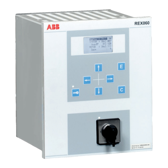
REX060 start up sequence GUID-63A15CD3-17B0-41DD-9611-8272DDA53137 v1 When the injection unit REX060 is energized, the ABB logotype is shown followed by current REX060 revision status. When the start up sequence is completed, the main menu (normal display content) is shown. The duration of the start up sequence is a few seconds. -
Page 52: Setting Up Communication Between Pcm600 And The Ied
Alternatively the default IP address for the IED front port is 10.1.150.3 and the corresponding subnetwork mask is 255.255.255.0, which can be set via the local HMI path Main menu/Configuration/Communication/Ethernet configuration/AP_FRONT. Generator protection REG670 2.2 IEC and Injection equipment REX060, REX061, REX062 Commissioning manual... - Page 53 Select Search programs and files in the Start menu in Windows. IEC13000057-1-en.vsd IEC13000057 V1 EN-US Figure 3: Select: Search programs and files Type View network connections and click on the View network connections icon. Generator protection REG670 2.2 IEC and Injection equipment REX060, REX061, REX062 Commissioning manual...
- Page 54 IEC13000059 V1 EN-US Figure 5: Right-click Local Area Connection and select Properties Select the TCP/IPv4 protocol from the list of configured components using this connection and click Properties. Generator protection REG670 2.2 IEC and Injection equipment REX060, REX061, REX062 Commissioning manual...
- Page 55 IP address is not set to be obtained automatically by the IED, see Figure 7. The IP address must be different from the IP address chosen for the IED. Generator protection REG670 2.2 IEC and Injection equipment REX060, REX061, REX062 Commissioning manual...
-
Page 56: Writing An Application Configuration To The Ied
When the IED is set in configuration mode, all functions are blocked. The red LED on the IED flashes, and the green LED is lit while the IED is in the configuration mode. Generator protection REG670 2.2 IEC and Injection equipment REX060, REX061, REX062 Commissioning manual... -
Page 57: Checking Ct Circuits
Both the primary and the secondary sides must be disconnected from the line and the IED when plotting the excitation characteristics. Generator protection REG670 2.2 IEC and Injection equipment REX060, REX061, REX062 Commissioning manual... -
Page 58: Checking Vt Circuits
In this position, the current and voltage enter the protection, but the alarm and trip circuits are still isolated and the IED is in test mode. Before removing the test handle, check the measured values in the IED. Generator protection REG670 2.2 IEC and Injection equipment REX060, REX061, REX062 Commissioning manual... -
Page 59: Checking The Binary Input/Output Circuits
Preferably, disconnect the binary output connector from the binary output cards. Check all connected signals so that both load and polarity are in accordance with IED specifications. Generator protection REG670 2.2 IEC and Injection equipment REX060, REX061, REX062 Commissioning manual... -
Page 60: Checking Optical Connections
An IED equipped with optical connections has an minimum space requirement of 180 mm for plastic fiber cables and 275 mm for glass fiber cables. Check the allowed minimum bending radius from the optical cable manufacturer. Generator protection REG670 2.2 IEC and Injection equipment REX060, REX061, REX062 Commissioning manual... -
Page 61: Section 5 Configuring The Ied And Changing Settings
IED. After that time has elapsed, it will be safe to turn the IED off, no data will be lost. Generator protection REG670 2.2 IEC and Injection equipment REX060, REX061, REX062 Commissioning manual... -
Page 62: Configuring Analog Ct Inputs
Supervision of input/output modules M11728-2 v3 I/O modules configured with PCM600 (BIM, BOM or IOM) are supervised. I/O modules that are not configured are not supervised. Generator protection REG670 2.2 IEC and Injection equipment REX060, REX061, REX062 Commissioning manual... - Page 63 Each logical I/O module has an error flag that indicates signal or module failure. The error flag is also set when the physical I/O module of the correct type is not detected in the connected slot. Generator protection REG670 2.2 IEC and Injection equipment REX060, REX061, REX062 Commissioning manual...
-
Page 65: Section 6 Calibrating Injection Based Sensitive Rotor Earth Fault Protection
The check of signal levels need the setting of the gain according to the value that is selected in REX060. Generator protection REG670 2.2 IEC and Injection equipment REX060, REX061, REX062 Commissioning manual... - Page 66 This is graphically shown in a diagram. The user stops the sequence by acceptance of the measurement. The result is stored for later calculations. Generator protection REG670 2.2 IEC and Injection equipment REX060, REX061, REX062 Commissioning manual...
-
Page 67: Launching Injection Commissioning Tool (Ict)
In the auditing part calibration and commissioning reports are stored. Launching injection commissioning tool (ICT) GUID-15CAE2A3-FA17-4119-9188-824C7F309D4B v2 To launch the Injection commissioning tool (ICT), right-click REG670 in the PCM plant structure and select the Injection commissioning. In the ICT toolbar, select the Rotor Earth Fault function. - Page 68 When the installing procedure is successful, select the Submit and save in report button. ICT will now forward a more accurate frequency to Parameter setting. In the Parameter setting tool, write the newly acquired parameter to IED. Generator protection REG670 2.2 IEC and Injection equipment REX060, REX061, REX062 Commissioning manual...
-
Page 69: Performing Calibration
Submit button. Clicking the Submit button the result is stored for later calculations. ICT automatically shifts to the second calibration sub tab, Step 2: Measurement Generator protection REG670 2.2 IEC and Injection equipment REX060, REX061, REX062 Commissioning manual... - Page 70 Connected impedance field and type 0 in the imaginary part field. This informs the ICT that we have connected a pure resistive impedance that has a value equal to the typed one. Generator protection REG670 2.2 IEC and Injection equipment REX060, REX061, REX062 Commissioning manual...
- Page 71 12.1. If a failure is indicated during one or more check(s), follow the instructions/tips provided by the ICT in the Calibration result field. 12.2. If these tips do not solve the issue, then contact ABB Support. Generator protection REG670 2.2 IEC and Injection equipment REX060, REX061, REX062...
-
Page 72: Acquiring References
The below description assumes that reference 1 was set during calibration and that a second reference must be set now. Generator protection REG670 2.2 IEC and Injection equipment REX060, REX061, REX062 Commissioning manual... - Page 73 Click the Select button when the standard deviation has converged so that its magnitude is within the noise level of the measured absolute impedance. Generator protection REG670 2.2 IEC and Injection equipment REX060, REX061, REX062 Commissioning manual...
-
Page 74: Verifying Calibration
To see these, select the available quantities under the Viewed quantity drop-down menu under the Monitoring tab. Observe the fault conductance while applying known faults. Generator protection REG670 2.2 IEC and Injection equipment REX060, REX061, REX062 Commissioning manual... - Page 75 11. Verify that TRIP and ALARM signals are connected to tripping/alarming/ signaling/communication in accordance with the scheme design. It is very important that the Function Tripping is Enabled under the following situations: Generator protection REG670 2.2 IEC and Injection equipment REX060, REX061, REX062 Commissioning manual...
-
Page 76: Auditing
Click the Delete report button in the upper right corner of the auditing screen. • Select a record with the mouse cursor then press the Delete key on the keyboard. Generate logs in one of the following ways: Generator protection REG670 2.2 IEC and Injection equipment REX060, REX061, REX062 Commissioning manual... -
Page 77: Editing Features In Graph
IEC11000051-1-en.vsd GUID-3F080E48-8B77-48A0-8283-89511E1AE50B V1 EN-US Figure 16: Zooming via the shortcut menu • Use the mouse to zoom in and select a part of the graph area. Generator protection REG670 2.2 IEC and Injection equipment REX060, REX061, REX062 Commissioning manual... -
Page 78: Logging Measurements To File
ICT continuously logs data to this file with logging interval set under graph update period. Notice that there is a field named Log period and its default Generator protection REG670 2.2 IEC and Injection equipment REX060, REX061, REX062 Commissioning manual... - Page 79 1 hour. The period can be adjusted before the logging is started, if needed. The logging can be stopped by selecting the Stop button. You can open the file in notepad or MS Excel. Generator protection REG670 2.2 IEC and Injection equipment REX060, REX061, REX062 Commissioning manual...
-
Page 81: Section 7 Calibrating Injection Based 100% Stator Earth Fault Protection
Installing During the installation, several checks are performed about both status of the function and levels of the injected current and voltage. The check of signal levels Generator protection REG670 2.2 IEC and Injection equipment REX060, REX061, REX062 Commissioning manual... - Page 82 IEC11000044-1-en.vsd GUID-9E470F57-D670-430C-BD27-CBF11AF92D1E V1 EN-US Figure 18: Different steps at calibration measurements There are other generator grounding methods and injection alternatives; the injection can be performed through: Generator protection REG670 2.2 IEC and Injection equipment REX060, REX061, REX062 Commissioning manual...
- Page 83 Generator voltage > set value and generator circuit breaker closed: Reference impedance 3 For more information see separate application note 1MRG005030 Application example for injection based 100% Stator EF and Sensitive Rotor EF protection. Generator protection REG670 2.2 IEC and Injection equipment REX060, REX061, REX062 Commissioning manual...
-
Page 84: Launching Injection Commissioning Tool (Ict)
In the auditing part installation, calibration and commissioning reports are stored. Launching injection commissioning tool (ICT) GUID-7CDFB043-26E1-4169-9D2C-BE7C5C08AEAE v2 To launch the Injection commissioning tool (ICT), right-click REG670 in the PCM plant structure and select the Injection commissioning. In the ICT toolbar, select the 100% Stator Earth Fault function. -
Page 85: Performing Calibration
When the statistical error of the performed continuous measurements reaches an acceptable value, the indicator bar reaches the stability region (turned green) and it is allowed to select the Submit button. Generator protection REG670 2.2 IEC and Injection equipment REX060, REX061, REX062 Commissioning manual... - Page 86 The total impedance to ground of the stator windings at the injection frequency taking into account the equivalent resistance R ,eq of the grounding resistor transferred to the primary side of the grounding transformer: Generator protection REG670 2.2 IEC and Injection equipment REX060, REX061, REX062 Commissioning manual...
- Page 87 (too low changes may be related to a grounded system at the beginning of the calibration) and that no problem affected the installation and calibration procedure. Generator protection REG670 2.2 IEC and Injection equipment REX060, REX061, REX062 Commissioning manual...
-
Page 88: Acquiring References
12.1. If a failure is indicated during one or more check(s), follow the instructions/tips provided by the ICT in the Calibration result field. 12.2. If these tips do not solve the issue, then contact ABB Support. IEC11000048-2-en.vsd GUID-D024D8B7-45F3-42D1-AAA3-488A2996267B V1 EN-US... - Page 89 By observing the standard deviation of the measured impedance, the commissioning engineer can decide if the impedance of the generator is stable/settled, and also if the average impedance is based on enough values so Generator protection REG670 2.2 IEC and Injection equipment REX060, REX061, REX062 Commissioning manual...
-
Page 90: Verifying Calibration
Set the graph update period to one second by typing 1 into the Graph update period field. To start continuously plotting values on the graph with one second interval, select Start readings values from IED. Generator protection REG670 2.2 IEC and Injection equipment REX060, REX061, REX062 Commissioning manual... - Page 91 9.3. By default the trip level is set to 1kΩ. In other words, if the fault resistance is lower, then the function issue trips. 10. Verify the measurements by applying various faults. Generator protection REG670 2.2 IEC and Injection equipment REX060, REX061, REX062 Commissioning manual...
-
Page 92: Auditing
Click the View report button in the upper right corner of the auditing screen. • Double click a report record. Delete reports in one of the following ways: Generator protection REG670 2.2 IEC and Injection equipment REX060, REX061, REX062 Commissioning manual... -
Page 93: Editing Features In Graph
IEC11000051-1-en.vsd GUID-3F080E48-8B77-48A0-8283-89511E1AE50B V1 EN-US Figure 26: Zooming via the shortcut menu • Use the mouse to zoom in and select a part of the graph area. Generator protection REG670 2.2 IEC and Injection equipment REX060, REX061, REX062 Commissioning manual... -
Page 94: Logging Measurements To File
ICT continuously logs data to this file with logging interval set under graph update period. Notice that there is a field named Log period and its default Generator protection REG670 2.2 IEC and Injection equipment REX060, REX061, REX062 Commissioning manual... - Page 95 1 hour. The period can be adjusted before the logging is started, if needed. The logging can be stopped by selecting the Stop button. You can open the file in notepad or MS Excel. Generator protection REG670 2.2 IEC and Injection equipment REX060, REX061, REX062 Commissioning manual...
-
Page 97: Section 8 Establishing Connection And Verifying The Spa/Iec Communication
HFBR • glass fibres with connector type ST When using the IEC protocol, the rear SPA/IEC port must be set for IEC use. Procedure: Generator protection REG670 2.2 IEC and Injection equipment REX060, REX061, REX062 Commissioning manual... -
Page 98: Verifying The Communication
IEC. The configuration must be made with the PCM600 software. Verify that the event is presented in the IEC master system. Generator protection REG670 2.2 IEC and Injection equipment REX060, REX061, REX062 Commissioning manual... -
Page 99: Fibre Optic Loop
1 dB Losses in connection box, two contacts (1 dB/contact) 2 dB Margin for 2 repair splices (0.5 dB/splice) 1 dB Maximum total attenuation 11 dB 7 dB Generator protection REG670 2.2 IEC and Injection equipment REX060, REX061, REX062 Commissioning manual... -
Page 101: Section 9 Establishing Connection And Verifying The Lon Communication
IEDs through the LON bus from the operator’s workplace, from the control center and also from other IEDs via bay-to-bay horizontal communication. For LON communication an SLM card should be ordered for the IEDs. Generator protection REG670 2.2 IEC and Injection equipment REX060, REX061, REX062 Commissioning manual... -
Page 102: The Lon Protocol
Use the LON Network Tool (LNT) to set the LON communication. This is a software tool applied as one node on the LON bus. To communicate via LON, the IEDs need to know Generator protection REG670 2.2 IEC and Injection equipment REX060, REX061, REX062 Commissioning manual... - Page 103 0 - 6 No value Location of the node *Can be viewed on the local HMI ADE settings are available on the local HMI under Main menu/Configuration/ Communication/Station communicaton/LON/ADE:1 Generator protection REG670 2.2 IEC and Injection equipment REX060, REX061, REX062 Commissioning manual...
-
Page 104: Optical Budget Calculation For Serial Communication With Lon
Losses in connection box, two contacts (0.75 dB/contact) 1.5 dB Losses in connection box, two contacts (1dB/contact) 2 dB Margin for repair splices (0.5 dB/splice) 0.5 dB Maximum total attenuation 11 dB 7 dB Generator protection REG670 2.2 IEC and Injection equipment REX060, REX061, REX062 Commissioning manual... -
Page 105: Section 10 Establishing Connection And Verifying The Iec 61850 Communication
There are no settings needed for the IEC/UCA 61850-9-2LE communication in the local HMI branch Station communication. Make sure that the optical fibres are connected correctly. Communication is enabled whenever the merging unit starts sending data. Generator protection REG670 2.2 IEC and Injection equipment REX060, REX061, REX062 Commissioning manual... -
Page 106: Verifying The Communication
Error and the that other signal is shown as Ok. Be sure to re-connect the removed connection after completed verification. Generator protection REG670 2.2 IEC and Injection equipment REX060, REX061, REX062 Commissioning manual... -
Page 107: Section 11 Establishing Connection And Verifying The Ieee C37.118/1344 Communication
1.2. Enable sending the frequency data by setting the parameter SendFreqInfo to On. Check the operation of the required phasor channels (PHASORREPORT) by navigating to: Main menu/Configuration/Communication/Station communication/phasor measurement/PMU Report/PHASORREPORT:x. Generator protection REG670 2.2 IEC and Injection equipment REX060, REX061, REX062 Commissioning manual... -
Page 108: Setting The Pmu Station Communication (Pmu Configuration)
LAN IP address of the PC is used, where the PDC client tool is installed. 3.3. The default parameter settings can be used for the rest of parameters for the first UDP group. Generator protection REG670 2.2 IEC and Injection equipment REX060, REX061, REX062 Commissioning manual... -
Page 109: Setting The Tcp/Udp Client Communication
IEEE C37.118 connection with the PMU: Set the IP stack on PMU Connection Tester to IPv4. Note that the default IP stack on PMU Connection Tester tool is IPv6. Generator protection REG670 2.2 IEC and Injection equipment REX060, REX061, REX062 Commissioning manual... - Page 110 LANAB:1 IPAddress (192.168.1.10) is set. 2.2. Set Port to the IED's TCP port set in the PMU under parameter C37.118TCPport (4712 is default). Alternatively, in order to make an Generator protection REG670 2.2 IEC and Injection equipment REX060, REX061, REX062 Commissioning manual...
- Page 111 TCP channel. A new window will pop up. A TCP channel needs to be configured in order to control the UDP data communicatiuon and transfer the header, configuration and command frames. Generator protection REG670 2.2 IEC and Injection equipment REX060, REX061, REX062 Commissioning manual...
-
Page 112: Verifying The Communication
C37.118/1344 communication. The section Setting the TCP/UDP client communication explains how to set the PMU Connection Tester parameters in order to establish an IEEE C37.118 connection with the PMU. Generator protection REG670 2.2 IEC and Injection equipment REX060, REX061, REX062 Commissioning manual... -
Page 113: Verifying The Ieee C37.118/1344 Tcp Communication
Graph tab, observe the Frequency, data Reporting Rate, Phasor names, and Phase angles of the reported synchrophasors. Observe the real-time frame details of the Data Frame in the bottom of the window. Generator protection REG670 2.2 IEC and Injection equipment REX060, REX061, REX062 Commissioning manual... - Page 114 (PMU Connection Tester) to the PMU. Try different commands and make sure that the PMU is receiving and responding to them. Generator protection REG670 2.2 IEC and Injection equipment REX060, REX061, REX062 Commissioning manual...
- Page 115 If the HeaderFrame is not included, ask the PMU to send the header frame via the Send Header Frame command (Previous stage). Open each message type and observe the content of each message. Generator protection REG670 2.2 IEC and Injection equipment REX060, REX061, REX062 Commissioning manual...
- Page 116 This is done by navigating to File/Capture/Start Stream Debug Capture... The tool will ask to Set Stream Debug Capture File Name and path to save the capture file. Generator protection REG670 2.2 IEC and Injection equipment REX060, REX061, REX062 Commissioning manual...
- Page 117 Start capturing the IEEE C37.118 synchrophasor data • The synchrophasor data capturing process can be stopped at any point of time by navigating to File/Capture/Stop Stream Debug Capture... Generator protection REG670 2.2 IEC and Injection equipment REX060, REX061, REX062 Commissioning manual...
- Page 118 Phasor names on top of each column (See figure 36), the capture process should start before connecting the PMU Connection Tester to the PMU, i.e. first start the capturing and then click Connect. Generator protection REG670 2.2 IEC and Injection equipment REX060, REX061, REX062 Commissioning manual...
-
Page 119: Verifying The Ieee C37.118/1344 Udp Communication
Now it should be possible to see the streaming synchrophasor data. • Verify the communication by following the same steps as in section Verifying the IEEE C37.118/1344 TCP communication. Generator protection REG670 2.2 IEC and Injection equipment REX060, REX061, REX062 Commissioning manual... -
Page 120: Optical Budget Calculation For Pmu - Pdc Communication
Losses in the connectors and splices are typically 0.3dB/connection. The user must reserve 3dB spare for the uncertainty of the measurements. Generator protection REG670 2.2 IEC and Injection equipment REX060, REX061, REX062 Commissioning manual... -
Page 121: Section 12 Testing Ied Operation
If the test equipment cannot indicate the phase angle, a separate phase-angle measuring instrument is necessary. Generator protection REG670 2.2 IEC and Injection equipment REX060, REX061, REX062 Commissioning manual... - Page 122 Some time must pass before the IED is restarted. For more information about the flash memory, refer to section “Configuring the IED and changing settings”. Generator protection REG670 2.2 IEC and Injection equipment REX060, REX061, REX062 Commissioning manual...
-
Page 123: Preparing The Ied To Verify Settings
In certain cases, only modes with a high probability of coming into operation need to be checked when commissioned to verify the configuration and settings. Generator protection REG670 2.2 IEC and Injection equipment REX060, REX061, REX062 Commissioning manual... -
Page 124: Activating The Test Mode
Use COMBITEST test system to prevent unwanted tripping when the handle is withdrawn, since latches on the handle secure it in the half withdrawn position. In this position, all voltages and currents are restored and any re-energizing transients Generator protection REG670 2.2 IEC and Injection equipment REX060, REX061, REX062 Commissioning manual... -
Page 125: Connecting The Test Equipment To The Ied
IED under test. To ensure correct results, make sure that the IED as well as the test equipment are properly earthed before testing. Generator protection REG670 2.2 IEC and Injection equipment REX060, REX061, REX062 Commissioning manual... -
Page 126: Releasing The Function To Be Tested
HMI under Main menu/Test/Function test modes menu remains On, that is, the parameter Blocked is set to Yes and the parameter TESTMODE under Main menu/Test/IED test mode remains Generator protection REG670 2.2 IEC and Injection equipment REX060, REX061, REX062 Commissioning manual... -
Page 127: Verifying Analog Primary And Secondary Measurement
Inject an unsymmetrical three-phase voltage and current, to verify that phases are correctly connected. If some setting deviates, check the analog input settings under Main menu/Configuration/Analog modules Generator protection REG670 2.2 IEC and Injection equipment REX060, REX061, REX062 Commissioning manual... -
Page 128: Testing The Protection Functionality
12.8.2.1 Enable forcing by using LHMI GUID-41F7C636-75BC-42EF-A955-4BD9E347619E v2 Enable IED TESTMODE by setting IEDTestMode to On under Main menu/ Test/IED test mode/TESTMODE:1. Generator protection REG670 2.2 IEC and Injection equipment REX060, REX061, REX062 Commissioning manual... -
Page 129: Enable Forcing Using Testmode Function Block
Edit the input/output value directly to select the desired logical level, by doing following: Select the value line of the desired signal, see figure 40. Press the Enter key to edit the value. Generator protection REG670 2.2 IEC and Injection equipment REX060, REX061, REX062 Commissioning manual... - Page 130 It is possible to power-cycle the IED in this state without losing the forcing states and values. This means that once a signal is forced, and the IED remains in IED test mode, the input or output will Generator protection REG670 2.2 IEC and Injection equipment REX060, REX061, REX062 Commissioning manual...
-
Page 131: Forcing By Using Pcm600
Right click on the IED in the plant structure and select Signal Monitoring. Click on the List View tab. Click Forcing Session in the menu IED/Start Forcing. Generator protection REG670 2.2 IEC and Injection equipment REX060, REX061, REX062 Commissioning manual... - Page 132 IEC15000026 V1 EN-US This commits the values to the IED and exits the editing session. Click Cancel to abort the changes and revert back to actual IED values. Generator protection REG670 2.2 IEC and Injection equipment REX060, REX061, REX062 Commissioning manual...
-
Page 133: How To Undo Forcing Changes And Return The Ied To Normal Operation
Exit from the menu and click Yes in the Save dialogue box. This immediately undoes all forcing, regardless of how it was accomplished and disabled. 12.8.4.3 Undo forcing by using PCM600 GUID-CE7FD186-99FC-41C8-910F-894A57037777 v1 Generator protection REG670 2.2 IEC and Injection equipment REX060, REX061, REX062 Commissioning manual... - Page 134 LHMI. If the IED is left in test mode, then it is still possible to perform new forcing operations, both from LHMI and from PCM600 Generator protection REG670 2.2 IEC and Injection equipment REX060, REX061, REX062 Commissioning manual...
-
Page 135: Section 13 Testing Functionality By Secondary Injection
The Manual Trig can be started in two ways: From the local HMI under Main menu/Disturbance records. 1.1. Enter on the row at the bottom of the HMI called Manual trig. Generator protection REG670 2.2 IEC and Injection equipment REX060, REX061, REX062 Commissioning manual... -
Page 136: Event Recorder (Er) And Event List (El)
HMI under Main menu/Events, or in more details via the Event Viewer in PCM600. The internal FIFO register of all events will appear when the event viewer is launched. Generator protection REG670 2.2 IEC and Injection equipment REX060, REX061, REX062 Commissioning manual... -
Page 137: Identifying The Function To Test In The Technical Reference Manual
Depending on the power transformer vector group (Yd and so on), the single- phase injection current may appear as differential current in one or two phases and the operating value of the injected single-phase current will be different. Generator protection REG670 2.2 IEC and Injection equipment REX060, REX061, REX062 Commissioning manual... -
Page 138: Completing The Test
Note as well that used CT input in the IED must have ratio set as 1:1. This is essential for the measurement of the expected Generator protection REG670 2.2 IEC and Injection equipment REX060, REX061, REX062 Commissioning manual... -
Page 139: Completing The Test
13.3.3.1 Verifying the settings SEMOD155702-49 v4 Go to Main menu/Test/Function test modes/Differential protection and make sure all other functions, configured to the same current transformer Generator protection REG670 2.2 IEC and Injection equipment REX060, REX061, REX062 Commissioning manual... -
Page 140: Completing The Test
Restricted earth fault protection, low impedance REFPDIF SEMOD55252-82 v8 Prepare the IED for verification of settings outlined in Section "Preparing the IED to verify settings". 13.3.4.1 Verifying the settings SEMOD55252-86 v11 Generator protection REG670 2.2 IEC and Injection equipment REX060, REX061, REX062 Commissioning manual... -
Page 141: Completing The Test
Keep the current constant when measuring operating characteristics. Keep the current as close as possible to its rated value or lower. But make sure it is higher than the set minimum operating current. Generator protection REG670 2.2 IEC and Injection equipment REX060, REX061, REX062 Commissioning manual... -
Page 142: High Speed Distance Protection Zones, Quadrilateral And Mho Characteristic Zmfpdis
When the load current compensation is inactive, the dotted lines and test point 13 are valid. Test points 5, 6, and 7 are not valid for this measurement. Generator protection REG670 2.2 IEC and Injection equipment REX060, REX061, REX062 Commissioning manual... - Page 143 0.8 x RFPPZx/2 –0.4 x RLdFw x tan(ArgDir=20°) 0.4 x RLdFw 0.5 x X1 Exact –0.5 x R1 tan(ArgNegRes=30°) –0.23 x X1 Table continues on next page Generator protection REG670 2.2 IEC and Injection equipment REX060, REX061, REX062 Commissioning manual...
- Page 144 + X0 2 x R1 + R0 0.8 x (2 x X1 + X0 0.8 x (2 x R1 + R0 +RFPEZx Table continues on next page Generator protection REG670 2.2 IEC and Injection equipment REX060, REX061, REX062 Commissioning manual...
-
Page 145: Measuring The Operating Limit Of Set Values
Observe that the zones that are not tested have to be blocked and the zone that is tested has to be released. Repeat steps to find the operating value for the phase-to-earth fault L3- E according to figure and table 20. Generator protection REG670 2.2 IEC and Injection equipment REX060, REX061, REX062 Commissioning manual... -
Page 146: Measuring The Operating Time Of Distance Protection Zones
Ensure that the maximum continuous current to the IED does not exceed four times its rated value, if the measurement of the operating characteristics runs under constant voltage conditions. Generator protection REG670 2.2 IEC and Injection equipment REX060, REX061, REX062 Commissioning manual... - Page 147 R (Ohm/phase) 20° 40% of RLdFw 80% of RLdFw 0.5 x RFPPZx IEC05000368-4-en.vsdx IEC05000368 V4 EN-US Figure 44: Distance protection characteristic with test points for phase-to- phase measurements Generator protection REG670 2.2 IEC and Injection equipment REX060, REX061, REX062 Commissioning manual...
- Page 148 0.8 x X1 Exact –0.5 x R1 tan(ArgNegRes=30°) –0.37 x X1 0.5 x X1 0.5 x R1 0.5 x RFPPZx Table is used in conjunction with figure 44. Generator protection REG670 2.2 IEC and Injection equipment REX060, REX061, REX062 Commissioning manual...
- Page 149 0.85 x RFPEZx RLdFw x tan(ArgLd RLdFw RLdFw –02143 x RLdFw Exact: 0.8 x RFPEZx x tan (ArgDir=20°) 0.8 x RLdFw Table continues on next page Generator protection REG670 2.2 IEC and Injection equipment REX060, REX061, REX062 Commissioning manual...
-
Page 150: Measuring The Operating Limit Of Set Values
(forward or reverse). 13.4.3.2 Measuring the operating time of distance protection zones GUID-70AEC42A-9BC7-445A-AE21-2CEC0C3A79DC v3 Procedure: Generator protection REG670 2.2 IEC and Injection equipment REX060, REX061, REX062 Commissioning manual... -
Page 151: Completing The Test
(IBase). The angle between the voltage and current shall be 0°. With maintained amplitude of the injected voltage the current amplitude and angle is changed to a value ZC/2. Generator protection REG670 2.2 IEC and Injection equipment REX060, REX061, REX062 Commissioning manual... - Page 152 In addition to this the signal ZONE2 should be activated. Set N2Limit to 1 and repeat step 6. Now the signals TRIP2 and TRIP should be activated. Generator protection REG670 2.2 IEC and Injection equipment REX060, REX061, REX062 Commissioning manual...
- Page 153 Zone 1 Zone 2 X’ Pole slip impedance movement Zone 2 TripAngle Zone 1 WarnAngle IEC07000099_2_en.vsd IEC07000099 V2 EN-US Figure 46: Setting of the pole slip protection PSPPPAM Generator protection REG670 2.2 IEC and Injection equipment REX060, REX061, REX062 Commissioning manual...
-
Page 154: Completing The Test
If there are several out-of-step relays in the power system, then the one which finds the center of oscillation in its zone 1 should operate first. Generator protection REG670 2.2 IEC and Injection equipment REX060, REX061, REX062 Commissioning manual... -
Page 155: Verifying The Settings
The test current is lower than the continuous permissive overload current I of the protection current channels of ovrl the transformer module. Generator protection REG670 2.2 IEC and Injection equipment REX060, REX061, REX062 Commissioning manual... - Page 156 (or in opposition), then the test is related to t,RZ1 the zone 1; if the test voltage is higher than V , then the test is related to the t,RZ1 zone 2. Generator protection REG670 2.2 IEC and Injection equipment REX060, REX061, REX062 Commissioning manual...
- Page 157 IED continuously. Limitations may be related to the available test set; the current I Generator protection REG670 2.2 IEC and Injection equipment REX060, REX061, REX062 Commissioning manual...
- Page 158 SE-RE that are too close to the R-axis because in that case the voltage is close to zero and, therefore, the impedance may approach a not defined quantity 0/0. Generator protection REG670 2.2 IEC and Injection equipment REX060, REX061, REX062 Commissioning manual...
-
Page 159: Fwdx )
Apply the following three-phase symmetrical quantities (the phase angle is related to phase L1): VT s 1 1 11931 95 1 × × × × t FwdZ 13 8 VT p (Equation 17) EQUATION14057 V1 EN-US Generator protection REG670 2.2 IEC and Injection equipment REX060, REX061, REX062 Commissioning manual... - Page 160 arctan arctan 82. . 14° ∠ = = ForwardR 8 19 (Equation 22) EQUATION14058 V1 EN-US Generator protection REG670 2.2 IEC and Injection equipment REX060, REX061, REX062 Commissioning manual...
- Page 161 Apply the following three-phase symmetrical quantities (the phase angle is related to phase L1): VT s 0 9 11931 77 81 × × × × t FwdZ 13 8 VT p (Equation 27) EQUATION14063 V1 EN-US Generator protection REG670 2.2 IEC and Injection equipment REX060, REX061, REX062 Commissioning manual...
- Page 162 arctan arctan 82. . 14° ∠ = = ForwardR 8 19 (Equation 32) EQUATION14058 V1 EN-US Generator protection REG670 2.2 IEC and Injection equipment REX060, REX061, REX062 Commissioning manual...
-
Page 163: Test Of The Boundary Between Zone 1 And Zone 2, Which Is Defined By The Parameter Reachz1
OutOfStep(78,Ucos)/OOSPPAM(78,Ucos):1/Outputs to check the available service values of the function block OOSPPAM. • Apply the following three-phase symmetrical quantities (the phase angle is related to phase L1): Generator protection REG670 2.2 IEC and Injection equipment REX060, REX061, REX062 Commissioning manual... - Page 164 Define the following three-phase symmetrical quantities (the phase angle is related to phase L1): VT s 1 1 1435 11 44 × × × × t RZ 13 8 VT p (Equation 41) EQUATION14065 V1 EN-US Generator protection REG670 2.2 IEC and Injection equipment REX060, REX061, REX062 Commissioning manual...
- Page 165 OutOfStep(78,Ucos)/OOSPPAM(78,Ucos):1/Outputs to check the available service values of the function block OOSPPAM. • Apply the following three-phase symmetrical quantities (the phase angle is related to phase L1): Generator protection REG670 2.2 IEC and Injection equipment REX060, REX061, REX062 Commissioning manual...
- Page 166 Define the following three-phase symmetrical quantities (the phase angle is related to phase L1): VT s 0 9 1435 9 36 × × × × t RZ 13 8 VT p (Equation 51) EQUATION14066 V1 EN-US Generator protection REG670 2.2 IEC and Injection equipment REX060, REX061, REX062 Commissioning manual...
- Page 167 EQUATION14062 V1 EN-US ∠I = 180º frequency of I = 49.5 Hz Expected result: start of the protection function and trip in zone 1 when trip conditions are fulfilled. Generator protection REG670 2.2 IEC and Injection equipment REX060, REX061, REX062 Commissioning manual...
-
Page 168: Test Of The Point Se (R Rvsr , X Rvsx )
Note that these values identify a point inside the lens characteristic in zone 1 that is close to the point SE. The START is issued, but no TRIP is performed. Generator protection REG670 2.2 IEC and Injection equipment REX060, REX061, REX062 Commissioning manual... - Page 169 = 0º frequency of I = 50 Hz 10459 1 162 × × 9000 (Equation 66) EQUATION14062 V1 EN-US ∠I = 180º frequency of I = 50.5 Hz Generator protection REG670 2.2 IEC and Injection equipment REX060, REX061, REX062 Commissioning manual...
- Page 170 ROTORANG= 0.08 rad Note that these values identify a point outside the lens characteristic, even if it is close to the point SE. Neither START nor TRIP is issued. Generator protection REG670 2.2 IEC and Injection equipment REX060, REX061, REX062 Commissioning manual...
- Page 171 = 0º frequency of I = 50 Hz 10459 1 162 × × 9000 (Equation 76) EQUATION14062 V1 EN-US ∠I = 180º frequency of I = 50.5 Hz Generator protection REG670 2.2 IEC and Injection equipment REX060, REX061, REX062 Commissioning manual...
-
Page 172: Loss Of Excitation Lexpdis
Feed the IED with current and voltage corresponding to the apparent impedance: Test #1, as shown in figure 50. Read the analog outputs for R and Generator protection REG670 2.2 IEC and Injection equipment REX060, REX061, REX062 Commissioning manual... - Page 173 Switch the current infeed injection off. The function shall reset. Turn the current on with the values corresponding to Test #4 and measure the time to activation of signal TRZ1. This time shall be compared to tZ1. Generator protection REG670 2.2 IEC and Injection equipment REX060, REX061, REX062 Commissioning manual...
-
Page 174: Completing The Test
Values of the logical signals for ZGVPDIS are available on the local HMI under Main menu/Tests/Function status/Impedance/ZGVPDIS (21G, Z<)/ 1:ZGVPDIS:ZGVPDIS. The Signal Monitoring in PCM600 shows the same signals that are available on the local HMI. Generator protection REG670 2.2 IEC and Injection equipment REX060, REX061, REX062 Commissioning manual... -
Page 175: Verifying The Settings
1 Z1Rev is the reverse positive sequence impedance setting for zone 1 LineAngle is the Impedance angle for phase-to-phase fault in degrees Generator protection REG670 2.2 IEC and Injection equipment REX060, REX061, REX062 Commissioning manual... - Page 176 (where x is 2- 3 depending on the zone selected) LineAngle is the Impedance angle for phase-to-phase fault in degrees Generator protection REG670 2.2 IEC and Injection equipment REX060, REX061, REX062 Commissioning manual...
- Page 177 Under voltage seal-in GUID-1219D2CC-D2EC-44B1-8F2E-A4C292590680 v2 The under voltage seal-in logic can be verified using the TRUV and STUV outputs. Steps to verify the logic: Generator protection REG670 2.2 IEC and Injection equipment REX060, REX061, REX062 Commissioning manual...
-
Page 178: Completing The Test
40 V AC is injected via series capacitors and resistors into the rotor circuit. The injected voltage is fed to a voltage input of the REG670 IED. The current caused by the injection is fed to a current input of the REG670 IED via a current transformer, which is amplifying the current ten times, as shown in figure 53. - Page 179 First the 120 (230) V input to RXTTE4 is disconnected. This should give a signal from REG670 that the injection voltage is low. Reconnect the 120 (230) V input and check that the low injection voltage signal resets. Generator protection REG670 2.2 IEC and Injection equipment REX060, REX061, REX062 Commissioning manual...
-
Page 180: Completing The Test
IED, does not exceed four times the rated current value of the IED. 13.5.1.1 Measuring the operate limit of set values M11754-11 v7 Generator protection REG670 2.2 IEC and Injection equipment REX060, REX061, REX062 Commissioning manual... -
Page 181: Completing The Test
The verification of the non-directional phase overcurrent function is done as instructed below, but without applying any polarizing voltage. Connect the test set for current injection to the appropriate IED phases. Generator protection REG670 2.2 IEC and Injection equipment REX060, REX061, REX062 Commissioning manual... - Page 182 Check that all operate and start contacts operate according to the configuration (signal matrixes). Reverse the direction of the injected current and check that the protection does not operate. Generator protection REG670 2.2 IEC and Injection equipment REX060, REX061, REX062 Commissioning manual...
-
Page 183: Completing The Test
Switch the fault current off. Do not exceed the maximum permitted overloading of the current circuits in the IED. Compare the measured operating current with the set value. Generator protection REG670 2.2 IEC and Injection equipment REX060, REX061, REX062 Commissioning manual... -
Page 184: Completing The Test
For inverse time curves, check the operate time at a current equal to 110% of the operate current for txMin. Check that all operate and start contacts operate according to the configuration (signal matrixes) Generator protection REG670 2.2 IEC and Injection equipment REX060, REX061, REX062 Commissioning manual... -
Page 185: Four Step Non-Directional Earth Fault Protection
(default 5 % of Ub) and set the injection current to lag the voltage by an angle equal to the set reference characteristic angle (180° - AngleRCA) if the forward directional function is selected. Generator protection REG670 2.2 IEC and Injection equipment REX060, REX061, REX062 Commissioning manual... -
Page 186: Completing The Test
13.5.6 Sensitive directional residual overcurrent and power protection SDEPSDE SEMOD175060-3 v7 Prepare the IED for verification of settings outlined in Section "Preparing the IED to verify settings". Generator protection REG670 2.2 IEC and Injection equipment REX060, REX061, REX062 Commissioning manual... -
Page 187: Measuring The Operate And Time Limit For Set Values
Compare the result with the set value and make sure that the new injected 3I · cos φ is equal to the setting INcosPhi>.. Take the set characteristic into consideration, see Figure and Figure 56. Generator protection REG670 2.2 IEC and Injection equipment REX060, REX061, REX062 Commissioning manual... - Page 188 Continue to test another function or complete the test by setting the test mode to Off. RCADir Operate area 3 × ROADir IEC06000650_2_en.vsd IEC06000650 V2 EN-US Figure 55: Characteristic with ROADir restriction Generator protection REG670 2.2 IEC and Injection equipment REX060, REX061, REX062 Commissioning manual...
- Page 189 Compare the result with the set value and make sure that the new injected 3I · 3U · cos φ is equal to the setting SN>. Take the set characteristic into consideration, see figure and figure 56. Generator protection REG670 2.2 IEC and Injection equipment REX060, REX061, REX062 Commissioning manual...
- Page 190 The expected value depends on whether definite or inverse time was selected. Continue to test another function or complete the test by setting the test mode to Off. Generator protection REG670 2.2 IEC and Injection equipment REX060, REX061, REX062 Commissioning manual...
- Page 191 Inject a voltage 0.8 · UNRel> and a current high enough to operate the directional function at the chosen angle. Increase the voltage until the directional function is released. Compare the measured value with the set UNRel> operate value. Generator protection REG670 2.2 IEC and Injection equipment REX060, REX061, REX062 Commissioning manual...
-
Page 192: Completing The Test
0.60 · Time Constant 1 (Tau1). 12. Check that all trip and alarm contacts operate according to the configuration logic. Generator protection REG670 2.2 IEC and Injection equipment REX060, REX061, REX062 Commissioning manual... -
Page 193: Completing The Test
Apply the fault condition, including START of CCRBRF, with a current below the set IP>. Repeat the fault condition and increase the current in steps until a trip occurs. Compare the result with the set IP>. Generator protection REG670 2.2 IEC and Injection equipment REX060, REX061, REX062 Commissioning manual... -
Page 194: Checking The Residual (Earth Fault) Current Operate Value In> Set Below Ip
Verify that no re-trip, but back-up trip is achieved after set time. RetripMode = CB Pos Check Checking the re-trip with current check, M12104-48 v7 Generator protection REG670 2.2 IEC and Injection equipment REX060, REX061, REX062 Commissioning manual... -
Page 195: Verifying The Back-Up Trip Mode
IP> but above IN>. The residual earth-fault should then be above set IN>. Verify that back-up trip is achieved after set time. If selected, re-trip should also appear. Disconnect AC and START input signals. Generator protection REG670 2.2 IEC and Injection equipment REX060, REX061, REX062 Commissioning manual... -
Page 196: Verifying Instantaneous Back-Up Trip At Cb Faulty Condition
Apply the fault condition, including the start of CCRBRF, with the current above the set IP> value. Check that the re-trip, if selected, and back-up trip commands are achieved. Generator protection REG670 2.2 IEC and Injection equipment REX060, REX061, REX062 Commissioning manual... -
Page 197: Completing The Test
Activate the BLKDBYAR binary input. This test should be performed together with Autorecloser SMBRREC. Activate the EXTPDIND binary input. No TRIP signal should appear. Reset both BLKDBYAR and EXTPDIND binary inputs. Generator protection REG670 2.2 IEC and Injection equipment REX060, REX061, REX062 Commissioning manual... -
Page 198: Completing The Test
The test is made by means of injection of voltage and current where the amplitude of both current and voltage and the phase angle between the voltage and current Generator protection REG670 2.2 IEC and Injection equipment REX060, REX061, REX062 Commissioning manual... - Page 199 Angle1, angle for stage 1 (equal to 0° for low forward power protection and equal to Generator protection REG670 2.2 IEC and Injection equipment REX060, REX061, REX062 Commissioning manual...
-
Page 200: Completing The Test
1 (equal to 0° for low forward power protection and equal to 180° for reverse power protection). Check that the monitored active power is Generator protection REG670 2.2 IEC and Injection equipment REX060, REX061, REX062 Commissioning manual... -
Page 201: Completing The Test
See example below for 1 A rated current transformer. Inject pure negative sequence current, that is, phase currents with exactly same magnitude, reversed sequence and exactly 120° phase displaced into the Generator protection REG670 2.2 IEC and Injection equipment REX060, REX061, REX062 Commissioning manual... - Page 202 11. Finally check that start and trip information is stored in the event menu. Example CTprim The CT ratios for all three phases is 1000 A, IBase is 1000 A, and the following secondary currents are applied: Generator protection REG670 2.2 IEC and Injection equipment REX060, REX061, REX062 Commissioning manual...
-
Page 203: Completing The Test
11. Inject 95% of the set ArmU< value symmetric three-phase voltage to the IED. 12. Set the injected current to 200% of the operate level of the tested stage, switch on the current. The function does start and trip. Generator protection REG670 2.2 IEC and Injection equipment REX060, REX061, REX062 Commissioning manual... -
Page 204: Voltage-Restrained Time Overcurrent Protection Vrpvoc
IECEQUATION2433 V1 EN-US Third part of the characteristic (UHighLimit/100*UBase ≤ Restrain voltage): StartCurr IBase × × CTprim (Equation 91) IECEQUATION2434 V1 EN-US Example (rated secondary current = 1A): Generator protection REG670 2.2 IEC and Injection equipment REX060, REX061, REX062 Commissioning manual... - Page 205 If definite time delay is used for the overcurrent step, set the setting Characterist = IEC Def. Time. Apply the voltages related to the last part of Generator protection REG670 2.2 IEC and Injection equipment REX060, REX061, REX062 Commissioning manual...
- Page 206 14. Note the operate value. The set operate value in secondary volts is calculated according to the following equation: StartVolt UBase × × VTprim (Equation 93) IECEQUATION2436 V1 EN-US Generator protection REG670 2.2 IEC and Injection equipment REX060, REX061, REX062 Commissioning manual...
-
Page 207: Completing The Test
Therefore either wait until set tReset time has elapsed, between two shots, or reset this memory by setting the RESET input into the function to value TRUE Generator protection REG670 2.2 IEC and Injection equipment REX060, REX061, REX062 Commissioning manual... -
Page 208: Completing The Test
Precautions if MeasurCurrent = DC. The magnitude of the injected current have to be decreased by multiplying it with a factor of 0.741 in order to get correct operate times when testing with three-phase symmetrical sinusoidal currents. Generator protection REG670 2.2 IEC and Injection equipment REX060, REX061, REX062 Commissioning manual... -
Page 209: Completing The Test
Prepare the IED for verification of settings outlined in Section "Preparing the IED to verify settings". 13.6.1.1 Verifying the settings M13796-9 v3 Verification of start value and time delay to operate for Step 1 M13796-29 v10 Generator protection REG670 2.2 IEC and Injection equipment REX060, REX061, REX062 Commissioning manual... - Page 210 For example, if the measured voltage jumps from the rated value to 0.8 times the set start voltage level and time multiplier k1 is set to 0.05 s (default Generator protection REG670 2.2 IEC and Injection equipment REX060, REX061, REX062 Commissioning manual...
-
Page 211: Completing The Test
Set and apply about 20% higher voltage than the measured operate value for one phase. Measure the time delay for the TR1 signal and compare it with the set value. Generator protection REG670 2.2 IEC and Injection equipment REX060, REX061, REX062 Commissioning manual... -
Page 212: Extended Testing
Check the inverse time delay by injecting a voltage corresponding to 1.2 × U1>. For example, if the inverse time curve A is selected, the trip signals TR1 and TRIP operate after a time corresponding to the equation: Generator protection REG670 2.2 IEC and Injection equipment REX060, REX061, REX062 Commissioning manual... -
Page 213: Completing The Test
10. Set the time delay to the correct value according to the setting plan and check the time delay tMin, injecting a voltage corresponding to 1.2 · V/Hz>>. Generator protection REG670 2.2 IEC and Injection equipment REX060, REX061, REX062 Commissioning manual... -
Page 214: Completing The Test
Apply voltage higher than the highest set value of UDTrip, U1Low and U2Low to the U1 three-phase inputs and to one phase of the U2 inputs according to figure 58. The voltage differential START signal is set. Generator protection REG670 2.2 IEC and Injection equipment REX060, REX061, REX062 Commissioning manual... - Page 215 (UL1 to UL2, UL2 to UL3, UL3 to UL1) Check of U2Low SEMOD175258-91 v3 Procedure Connect voltages to the IED according to valid connection diagram and figure 59. Generator protection REG670 2.2 IEC and Injection equipment REX060, REX061, REX062 Commissioning manual...
-
Page 216: Check Of Voltage Differential Trip And Alarm Levels
U2Low. 13.6.5.2 Check of voltage differential trip and alarm levels SEMOD175258-104 v3 Procedure Connect voltages to the IED according to valid connection diagram and figure 60. Generator protection REG670 2.2 IEC and Injection equipment REX060, REX061, REX062 Commissioning manual... -
Page 217: Check Of Trip And Trip Reset Timers
Observe that the connections to U1 must be shifted to test another phase. (UL1 to UL2, UL2 to UL3, UL3 to UL1) 13.6.5.3 Check of trip and trip reset timers SEMOD175258-124 v2 Procdure Generator protection REG670 2.2 IEC and Injection equipment REX060, REX061, REX062 Commissioning manual... -
Page 218: Final Adjustment Of Compensation For Vt Ratio Differences
100% Stator earth fault protection, 3rd harmonic based STEFPHIZ SEMOD158990-3 v4 Prepare the IED for verification of settings outlined in Section "Preparing the IED to verify settings". Generator protection REG670 2.2 IEC and Injection equipment REX060, REX061, REX062 Commissioning manual... -
Page 219: Testing
× × cos(ANGLE) sin(ANGLE) (Equation 101) EQUATION2071 V1 EN-US Decrease the value of the injected voltage U until the signal START3H is activated. Check that Generator protection REG670 2.2 IEC and Injection equipment REX060, REX061, REX062 Commissioning manual... -
Page 220: Verifying Settings
The operate value should be above the measured residual third-harmonic voltage in the neutral point at normal operation (non-faulted generator). Generator protection REG670 2.2 IEC and Injection equipment REX060, REX061, REX062 Commissioning manual... -
Page 221: Completing The Test
Note that the measured time consists of the set value of the time delay plus the minimum operate time of the start function (80 - 90 ms). Extended testing M16289-31 v6 Generator protection REG670 2.2 IEC and Injection equipment REX060, REX061, REX062 Commissioning manual... -
Page 222: Completing The Test
10% longer than tDelay. Note the operate value and compare it with the set value. Decrease the frequency to rated operating conditions. Check that the START signal resets. Generator protection REG670 2.2 IEC and Injection equipment REX060, REX061, REX062 Commissioning manual... -
Page 223: Completing The Test
Prepare the IED for verification of settings outlined in Section "Preparing the IED to verify settings". 13.7.3.1 Verifying the settings M16256-8 v1 Verification of START value and time delay to operate M16256-10 v5 Generator protection REG670 2.2 IEC and Injection equipment REX060, REX061, REX062 Commissioning manual... -
Page 224: Completing The Test
Supply the IED with three-phase currents and voltages at their rated value. Slowly decrease the frequency of the applied voltage until it crosses the frequency high limit and the START signal appears. Generator protection REG670 2.2 IEC and Injection equipment REX060, REX061, REX062 Commissioning manual... - Page 225 Ensure that the setting CBCheck is enabled. Supply the IED with three-phase currents and voltages at their rated values. Slowly decrease the frequency of the applied voltage until the START signal appears. Generator protection REG670 2.2 IEC and Injection equipment REX060, REX061, REX062 Commissioning manual...
-
Page 226: Completing The Test
CVGAPC is that the value, which is processed and used for evaluation in the function, can be chosen in many different ways by the setting parameters CurrentInput and VoltageInput. Generator protection REG670 2.2 IEC and Injection equipment REX060, REX061, REX062 Commissioning manual... -
Page 227: Built-In Overcurrent Feature (Non-Directional)
10. Finally check that START and TRIP information is stored in the event menu. Information on how to use the event menu is found in the operator's manual. Generator protection REG670 2.2 IEC and Injection equipment REX060, REX061, REX062 Commissioning manual... -
Page 228: Overcurrent Feature With Current Restraint
I · cos(F). This has to be known if a more detailed measurement of the directional characteristic is made, than the one described below. Procedure Generator protection REG670 2.2 IEC and Injection equipment REX060, REX061, REX062 Commissioning manual... -
Page 229: Over/Undervoltage Feature
The Current circuit supervision function CCSSPVC is conveniently tested with the same three-phase test set as used when testing the measuring functions in the IED. Generator protection REG670 2.2 IEC and Injection equipment REX060, REX061, REX062 Commissioning manual... -
Page 230: Verifying The Settings
Only the distance protection function can operate. • Undervoltage-dependent functions must not operate. Disconnect the dc voltage from the DISCPOS binary input terminal. Connect the nominal dc voltage to the MCBOP binary input. Generator protection REG670 2.2 IEC and Injection equipment REX060, REX061, REX062 Commissioning manual... -
Page 231: Measuring The Operate Value For The Negative Sequence Function
+ ⋅ (Equation 106) EQUATION707 V2 EN-US Where: are the measured phase voltages and U IEC00000275 V1 EN-US p × = × 0, 5 IECEQUATION00022 V2 EN-US Generator protection REG670 2.2 IEC and Injection equipment REX060, REX061, REX062 Commissioning manual... -
Page 232: Measuring The Operate Value For The Zero-Sequence Function
IEC00000275 V1 EN-US Compare the result with the set value of the zero-sequence operating voltage (consider that the set value 3U0> is in percentage of the base voltage.) Generator protection REG670 2.2 IEC and Injection equipment REX060, REX061, REX062 Commissioning manual... -
Page 233: Measuring The Operate Value For The Dead Line Detection Function
Change the voltages and currents in all three phases simultaneously. The voltage change must be higher than the set value DU> and the current change must be lower than the set value DI<. Generator protection REG670 2.2 IEC and Injection equipment REX060, REX061, REX062 Commissioning manual... -
Page 234: Completing The Test
Disconnect one of the phase voltage from the main fuse group or the pilot fuse group. Observe the binary outputs of the IED. The MAINFUF or the Generator protection REG670 2.2 IEC and Injection equipment REX060, REX061, REX062 Commissioning manual... -
Page 235: Completing The Test
Synchrocheck, energizing check, and synchronizing SESRSYN M2377-3 v12 This section contains instructions on how to test the synchrocheck, energizing check, and synchronizing function SESRSYN for single, double and 1½ breaker arrangements. Generator protection REG670 2.2 IEC and Injection equipment REX060, REX061, REX062 Commissioning manual... - Page 236 This description describes the test of the version intended for one bay. Figure shows the general test connection for a 1½ breaker diameter with one- phase voltage connected to the line side. Generator protection REG670 2.2 IEC and Injection equipment REX060, REX061, REX062 Commissioning manual...
- Page 237 U3PLN1 Input Phase L1,L2,L3 L12,L23,L31 IEC05000481-5-en.vsd IEC05000481 V5 EN-US Figure 63: General test connection for a 1½ breaker diameter with one-phase voltage connected to the line side Generator protection REG670 2.2 IEC and Injection equipment REX060, REX061, REX062 Commissioning manual...
-
Page 238: Testing The Synchronizing Function
UL1, UL2 or UL3 line 1 voltage input on the IED according to the connection in SMT U-Bus Bus voltage input on the IED according to the connection in SMT Generator protection REG670 2.2 IEC and Injection equipment REX060, REX061, REX062 Commissioning manual... - Page 239 ± dφ degrees, the user can check that the two outputs are activated for a phase difference lower than the set value. It should not operate for other values. See figure 64. Generator protection REG670 2.2 IEC and Injection equipment REX060, REX061, REX062 Commissioning manual...
- Page 240 If a modern test set is used, the frequency can be changed continuously. Testing the reference voltage M2377-249 v5 Use the same basic test connection as in figure 62. Generator protection REG670 2.2 IEC and Injection equipment REX060, REX061, REX062 Commissioning manual...
-
Page 241: Testing The Energizing Check
The test should verify that the energizing check function operates for a low voltage on the U-Bus and for a high voltage on the U-Line. This corresponds to an energizing of a dead bus to a live line. Generator protection REG670 2.2 IEC and Injection equipment REX060, REX061, REX062 Commissioning manual... -
Page 242: Testing The Voltage Selection
SESRSYN function used in a double-bus arrangement. Apply a single-phase voltage of 100% GblBaseSelLine to the U-Line and a single-phase voltage of 100% GblBaseSelBus to the U-Bus. Generator protection REG670 2.2 IEC and Injection equipment REX060, REX061, REX062 Commissioning manual... - Page 243 WA1 – LINE1_Q B1SEL, (Operates on LINE1 LN1SEL WA1_QA1) WA1 – TIE_QA1 LINE2_Q B1SEL, LINE2 LN2SEL WA1 – TIE_QA1 WA2_QA B1SEL, B2SEL Table continues on next page Generator protection REG670 2.2 IEC and Injection equipment REX060, REX061, REX062 Commissioning manual...
-
Page 244: Completing The Test
Continue to test another function or end the test by changing the TESTMODE setting to Off. Restore connections and settings to their original values, if they were changed for testing purposes. Generator protection REG670 2.2 IEC and Injection equipment REX060, REX061, REX062 Commissioning manual... -
Page 245: Apparatus Control Apc
Before starting any test, verify the following settings in PCM600 or the local HMI for TR1ATCC, TR8ATCC and TCMYLTC and TCLYLTC. • Confirm power system base quantities I1Base, I2Base, UBase. Generator protection REG670 2.2 IEC and Injection equipment REX060, REX061, REX062 Commissioning manual... - Page 246 It is important to review these settings and confirm the intended response of the voltage control function for different secondary injection tests. Generator protection REG670 2.2 IEC and Injection equipment REX060, REX061, REX062 Commissioning manual...
-
Page 247: Secondary Test
This command sequence will be repeated until U brought back within the inner deadband range. 13.10.3.2 Check the activation of the voltage control operation SEMOD175185-537 v8 Generator protection REG670 2.2 IEC and Injection equipment REX060, REX061, REX062 Commissioning manual... -
Page 248: Check The Normal Voltage Regulation Function
Detection of this command will involve locating the allocated binary output for a raise pulse command in the Signal Matrix in PCM600 and monitoring a positive from this output. Generator protection REG670 2.2 IEC and Injection equipment REX060, REX061, REX062 Commissioning manual... -
Page 249: Check The Undervoltage Block Function
HMI. For an alarm condition, the voltage regulation function is not blocked and a lower command should be issued from the IED. Generator protection REG670 2.2 IEC and Injection equipment REX060, REX061, REX062 Commissioning manual... -
Page 250: Check The Overcurrent Block Function
By separation of real and imaginary parts: × × ul re ub re rline il re xline il im (Equation 111) EQUATION2082 V1 EN-US Generator protection REG670 2.2 IEC and Injection equipment REX060, REX061, REX062 Commissioning manual... -
Page 251: Parallel Voltage Regulation
For parallel operation, it is also recommended to confirm for parallel group membership, defined by setting TnRXOP in the local HMI under Main menu/Settings/Setting group N/Control/ TransformerVoltageControl(ATCC,90)/TR8ATCC:x/ParCtrl Generator protection REG670 2.2 IEC and Injection equipment REX060, REX061, REX062 Commissioning manual... - Page 252 Generator protection REG670 2.2 IEC and Injection equipment REX060, REX061, REX062 Commissioning manual...
- Page 253 HMI (Icc_i), calculate the value for circulating current voltage adjustment Uci. × × Ci Icc i Xi (Equation 114) EQUATION2088 V1 EN-US Generator protection REG670 2.2 IEC and Injection equipment REX060, REX061, REX062 Commissioning manual...
- Page 254 Transformer 1. Magnitude and direction of circulating currents measured for each transformer can be observed as service values on the local HMI and raise/lower commands detected from the binary output mapped in the Signal Matrix. Generator protection REG670 2.2 IEC and Injection equipment REX060, REX061, REX062 Commissioning manual...
- Page 255 HMI. Confirm that the automatic voltage control for tap changer, parallel control function TR8ATCC responds in accordance with the setting for CircCurrBk. Generator protection REG670 2.2 IEC and Injection equipment REX060, REX061, REX062 Commissioning manual...
-
Page 256: Completing The Test
IED. It is recommended that the function is tested together with the autorecloser function, when built into the IED or when a separate external unit is used for reclosing purposes. 13.11.1.1 3 phase operating mode SEMOD54375-106 v10 Generator protection REG670 2.2 IEC and Injection equipment REX060, REX061, REX062 Commissioning manual... -
Page 257: 1Ph/3Ph Operating Mode
A single-phase fault shall be given at the first fault. A three-phase trip must be initiated for the second fault. Check that the corresponding trip signals appear after both faults. Functional outputs TRIP, TRLn and TR1P should be Generator protection REG670 2.2 IEC and Injection equipment REX060, REX061, REX062 Commissioning manual... -
Page 258: 1Ph/2Ph/3Ph Operating Mode
A single-phase fault shall be given at the first fault. A three-phase trip must be initiated for the second fault. Check that the corresponding trip signals appear after both faults. Functional outputs TRIP, TRLn and TR1P should be Generator protection REG670 2.2 IEC and Injection equipment REX060, REX061, REX062 Commissioning manual... -
Page 259: Circuit Breaker Lockout
10. Reset the lockout. All functional outputs should reset. 11. Deactivate the trip signal lockout function, set TripLockout = Off and the automatic lockout function, set AutoLock = Off. Generator protection REG670 2.2 IEC and Injection equipment REX060, REX061, REX062 Commissioning manual... -
Page 260: Completing The Test
Connect binary inputs to consider gas pressure and gas density to initiate the alarms. Consider the analogue pressure input SENPRES and set SENPRES to a value lower than PresAlmLimit or activate binary input signal SENPRESALM, check Generator protection REG670 2.2 IEC and Injection equipment REX060, REX061, REX062 Commissioning manual... -
Page 261: Testing The Gas Medium Supervision For Temperature Alarm And Temperature Lock Out Conditions
IED to verify settings" in this chapter. Values of logical signals for SSIMG protection are available on the local HMI under Main menu/Tests/Function status/Monitoring/InsulationLiquid(71)/ SSIML(71):x, where x = 1, 2,..4. Generator protection REG670 2.2 IEC and Injection equipment REX060, REX061, REX062 Commissioning manual... -
Page 262: Testing The Liquid Medium Supervision For Level Alarm And Level Lockout Conditions
Continue to test another function or end the test by changing the TestMode setting to Off. Restore connections and settings to their original values, if they were changed for testing purposes. Generator protection REG670 2.2 IEC and Injection equipment REX060, REX061, REX062 Commissioning manual... -
Page 263: Breaker Monitoring Sscbr
5.4. Check the circuit breaker is in INVDPOS if auxiliary contacts read same value or CB is open and inject the current in selected phase more than AccStopCurr set value. Test of remaining life of CB Generator protection REG670 2.2 IEC and Injection equipment REX060, REX061, REX062 Commissioning manual... - Page 264 PRESALM is enabled. 10.3. The output GPRESLO is activated after a set time of tDGasPresLO value if the input PRESLO is enabled. Generator protection REG670 2.2 IEC and Injection equipment REX060, REX061, REX062 Commissioning manual...
-
Page 265: Completing The Test
13.12.6 Estimation of transformer insulation life LOLSPTR GUID-C08B2360-2134-43DD-9F39-54CD9FA45B5B v1 Prepare the IED for verification of settings outlined in Section "Preparing the IED to verify settings". Generator protection REG670 2.2 IEC and Injection equipment REX060, REX061, REX062 Commissioning manual... -
Page 266: Verifying The Signals And Settings
WARNING1 signal. Make sure that the ALARM1 signal appears. 11. Note the time taken for the appearance of ALARM1 signal from the appearance of WARNING1 signal, and compare it with set value (tDelayToAlarm1). Generator protection REG670 2.2 IEC and Injection equipment REX060, REX061, REX062 Commissioning manual... -
Page 267: Completing The Test
The test of the Pulse-counter logic function PCFCNT requires the Parameter Setting tool in PCM600 or an appropriate connection to the local HMI with the necessary functionality. A known number of pulses with different frequencies are Generator protection REG670 2.2 IEC and Injection equipment REX060, REX061, REX062 Commissioning manual... -
Page 268: Function For Energy Calculation And Demand Handling Etpmmtr
12. Similarly the testing can be done for EAFACC and ERFACC outputs by changing the power inputs directions through direction settings. Verification of MAXPAFD & MAXPRFD outputs Generator protection REG670 2.2 IEC and Injection equipment REX060, REX061, REX062 Commissioning manual... -
Page 269: Completing The Test
MULTICMDSND) is only applicable for horizontal communication. Test of the multiple command function block and multiple transmit is recommended to be performed in a system, that is, either in a complete delivery Generator protection REG670 2.2 IEC and Injection equipment REX060, REX061, REX062 Commissioning manual... -
Page 270: Remote Communication
(BO). Check at End2 that the BI signal is received and the BO operates. Repeat the test for all the signals configured to be transmitted over the communication link. Generator protection REG670 2.2 IEC and Injection equipment REX060, REX061, REX062 Commissioning manual... -
Page 271: Basic Ied Functions
Operating procedures for the PC aided methods of changing the active setting groups are described in the corresponding PCM600 documents and instructions for the operators within the SCS are included in the SCS documentation. Generator protection REG670 2.2 IEC and Injection equipment REX060, REX061, REX062 Commissioning manual... -
Page 272: Completing The Test
Navigate to the test mode folder. Change the On setting to Off. Press the 'E' key and the left arrow key. Answer YES, press the 'E' key and exit the menus. Generator protection REG670 2.2 IEC and Injection equipment REX060, REX061, REX062 Commissioning manual... -
Page 273: Section 14 Checking The Directionality
Settings/IED Settings/Impedance protection/ DirectionalImpedance The primary load impedance must have an angle (PHI) between the setting angles for the directional lines. In case of default settings this means: Generator protection REG670 2.2 IEC and Injection equipment REX060, REX061, REX062 Commissioning manual... - Page 274 Generator protection REG670 2.2 IEC and Injection equipment REX060, REX061, REX062 Commissioning manual...
- Page 275 Generator protection REG670 2.2 IEC and Injection equipment REX060, REX061, REX062 Commissioning manual...
-
Page 277: Section 15 Commissioning And Maintenance Of The Fault Clearing System
The periodicity of all tests depends on several factors, for example the importance of the installation, environmental conditions, simple or complex equipment, static or electromechanical IEDs, and so on. The normal maintenance praxis of the user should be followed. However, ABB's recommendation is as follows: Every second to third year •... -
Page 278: Visual Inspection
IED at a time on live circuits where redundant protection is installed and de-energization of the primary circuit is not allowed. ABB protection IEDs are preferably tested by aid of components from the COMBITEST testing system described in information B03-9510 E. Main... -
Page 279: Recording
The healthy circuit is of utmost importance for the protection operation. If Generator protection REG670 2.2 IEC and Injection equipment REX060, REX061, REX062 Commissioning manual... -
Page 280: Measurement Of Service Currents
0.1 to 1V secondary. However, voltage can be considerably higher due to harmonics. Normally a CVT secondary can have around 2.5 - 3% third-harmonic voltage. Generator protection REG670 2.2 IEC and Injection equipment REX060, REX061, REX062 Commissioning manual... -
Page 281: Restoring
Thus a list should be prepared of all items disturbed during test so that all can be put back into service quickly and without overlooking something. It should be put back into service item by item and signed by the responsible engineer. Generator protection REG670 2.2 IEC and Injection equipment REX060, REX061, REX062 Commissioning manual... -
Page 283: Section 16 Troubleshooting
Real time clock Ready No problem detected. None. Real time clock Fail The real time clock has Set the clock. been reset. Table continues on next page Generator protection REG670 2.2 IEC and Injection equipment REX060, REX061, REX062 Commissioning manual... -
Page 284: Fault Tracing
READY / FAIL IOM-error. Input/Output Module Error status. MIMn READY / FAIL mA input module MIM1 failed. Signal activation will reset the IED Table continues on next page Generator protection REG670 2.2 IEC and Injection equipment REX060, REX061, REX062 Commissioning manual... -
Page 285: Using Front-Connected Pc
The internal events are time tagged with a resolution of 1ms and stored in a list. The list can store up to 40 events. The list is based on the FIFO principle, when it is Generator protection REG670 2.2 IEC and Injection equipment REX060, REX061, REX062 Commissioning manual... - Page 286 This means that, when using the PC for fault tracing, it provides information on the: • Module that should be changed. • Sequence of faults, if more than one unit is faulty. • Exact time when the fault occurred. Generator protection REG670 2.2 IEC and Injection equipment REX060, REX061, REX062 Commissioning manual...
-
Page 287: Diagnosing The Ied Status Via The Lhmi Hint Menu
PMU not connected to 3ph output The PMU phasor report input(s) must be connected to the 3ph output of SMAI or 3PHSU. Table continues on next page Generator protection REG670 2.2 IEC and Injection equipment REX060, REX061, REX062 Commissioning manual... - Page 288 Non ABB vendor SFP detected Non ABB vendor SFP detected. Corresponding hardware(s) is set to fail. Please use ABB approved SFP’s. Generator protection REG670 2.2 IEC and Injection equipment REX060, REX061, REX062 Commissioning manual...
-
Page 289: Repair Instruction
M11764-10 v1 An alternative is to open the IED and send only the faulty circuit board to ABB for repair. When a printed circuit board is sent to ABB, it must always be placed in a metallic, ESD-proof, protection bag. -
Page 290: Repair Support
Repair support M11768-3 v3 If an IED needs to be repaired, the whole IED must be removed and sent to an ABB Logistic Center. Before returning the material, an inquiry must be sent to the ABB Logistic Center. e-mail: offer.selog@se.abb.com 16.5... -
Page 291: Section 17 Glossary
Binary signal transfer function, transmit blocks C37.94 IEEE/ANSI protocol used when sending binary signals between IEDs Controller Area Network. ISO standard (ISO 11898) for serial communication Circuit breaker Combined backplane module Generator protection REG670 2.2 IEC and Injection equipment REX060, REX061, REX062 Commissioning manual... - Page 292 Defense Advanced Research Projects Agency (The US developer of the TCP/IP protocol etc.) DBDL Dead bus dead line DBLL Dead bus live line Direct current Data flow control Discrete Fourier transform Generator protection REG670 2.2 IEC and Injection equipment REX060, REX061, REX062 Commissioning manual...
- Page 293 Electrical and functional description for digital lines used by local telephone companies. Can be transported over balanced and unbalanced lines Communication interface module with carrier of GPS receiver module Generator protection REG670 2.2 IEC and Injection equipment REX060, REX061, REX062 Commissioning manual...
- Page 294 PCI specifications from the PCI SIG (Special Interest Group) for the electrical EMF (Electromotive force). IEEE 1686 Standard for Substation Intelligent Electronic Devices (IEDs) Cyber Security Capabilities Generator protection REG670 2.2 IEC and Injection equipment REX060, REX061, REX062 Commissioning manual...
- Page 295 Line data communication module Local detection device Light-emitting diode LON network tool Local operating network Miniature circuit breaker Mezzanine carrier module Milli-ampere module Main processing module MVAL Value of measurement Generator protection REG670 2.2 IEC and Injection equipment REX060, REX061, REX062 Commissioning manual...
- Page 296 Potential transformer or voltage transformer ratio PUTT Permissive underreach transfer trip RASC Synchrocheck relay, COMBIFLEX Relay characteristic angle RISC Reduced instruction set computer RMS value Root mean square value Generator protection REG670 2.2 IEC and Injection equipment REX060, REX061, REX062 Commissioning manual...
- Page 297 Switch for CB ready condition Switch or push button to trip Starpoint Neutral point of transformer or generator Static VAr compensation Trip coil Trip circuit supervision Generator protection REG670 2.2 IEC and Injection equipment REX060, REX061, REX062 Commissioning manual...
- Page 298 Gregorian calendar. It is used for aeroplane and ship navigation, where it is also sometimes known by the military name, "Zulu time." "Zulu" in the Generator protection REG670 2.2 IEC and Injection equipment REX060, REX061, REX062 Commissioning manual...
- Page 299 Three times zero-sequence current.Often referred to as the residual or the earth-fault current Three times the zero sequence voltage. Often referred to as the residual voltage or the neutral point voltage Generator protection REG670 2.2 IEC and Injection equipment REX060, REX061, REX062 Commissioning manual...
- Page 302 — ABB AB Grid Automation Products 721 59 Västerås, Sweden Phone: +46 (0) 21 32 50 00 abb.com/protection-control © Copyright 2017 ABB. All rights reserved. Specifications subject to change without notice.
Need help?
Do you have a question about the REG670 and is the answer not in the manual?
Questions and answers