ABB RELION REG670 Commissioning Manual
Generator protection
Hide thumbs
Also See for RELION REG670:
- Technical manual (1298 pages) ,
- Applications manual (780 pages) ,
- Commissioning manual (324 pages)

Subscribe to Our Youtube Channel
Related Manuals for ABB RELION REG670


Summary of Contents for ABB RELION REG670
- Page 1 — R E L I O N ® 670 SERIES Generator protection REG670 Version 2.1 IEC Commissioning manual...
- Page 3 Document ID: 1MRK 502 067-UEN Issued: March 2019 Revision: B Product version: 2.1 © Copyright 2016 ABB. All rights reserved...
- Page 4 Copyright This document and parts thereof must not be reproduced or copied without written permission from ABB, and the contents thereof must not be imparted to a third party, nor used for any unauthorized purpose. The software and hardware described in this document is furnished under a license and may be used or disclosed only in accordance with the terms of such license.
- Page 5 This document has been carefully checked by ABB but deviations cannot be completely ruled out. In case any errors are detected, the reader is kindly requested to notify the manufacturer.
- Page 6 (Low-voltage directive 2006/95/EC). This conformity is the result of tests conducted by ABB in accordance with the product standard EN 60255-26 for the EMC directive, and with the product standards EN 60255-1 and EN 60255-27 for the low voltage directive. The...
-
Page 7: Table Of Contents
Table of contents Table of contents Section 1 Introduction....................... 11 This manual............................11 Intended audience..........................11 Product documentation........................12 1.3.1 Product documentation set.......................12 1.3.2 Document revision history......................13 1.3.3 Related documents........................13 Document symbols and conventions...................14 1.4.1 Symbols............................14 1.4.2 Document conventions.......................15 IEC61850 edition 1 / edition 2 mapping..................15 Section 2 Safety information................... - Page 8 Table of contents 4.12 Checking optical connections....................... 48 Section 5 Configuring the IED and changing settings..........49 Overview............................49 Configuring analog CT inputs....................... 49 Reconfiguring the IED........................50 Section 6 Calibrating injection based sensitive rotor earth fault protection... 51 Commissioning process......................... 51 Commissioning tool ICT.........................
- Page 9 Table of contents 10.2 Setting the station communication.....................83 10.3 Verifying the communication......................84 Section 11 Testing IED operation..................85 11.1 Preparing for test..........................85 11.1.1 Requirements..........................85 11.1.2 Preparing the IED to verify settings..................86 11.2 Activating the test mode........................87 11.3 Preparing the connection to the test equipment..............87 11.4 Connecting the test equipment to the IED................
- Page 10 Table of contents 12.4.1 Distance protection zones, quadrilateral characteristic ZMQPDIS.........102 12.4.1.1 Measuring the operating limit of set values..............105 12.4.1.2 Measuring the operating time of distance protection zones........105 12.4.1.3 Completing the test......................106 12.4.2 Phase selection with load encroachment, quadrilateral characteristic FDPSPDIS ..106 12.4.2.1 Measuring the operating limit of set values..............108 12.4.2.2...
- Page 11 Table of contents 12.4.12.3 Initiating ZCVPSOF automatically and setting mode to UILevel ......... 147 12.4.12.4 Completing the test.......................147 12.4.13 Loss of excitation LEXPDIS ..................... 147 12.4.13.1 Verifying the settings......................148 12.4.13.2 Completing the test.......................149 12.4.14 Phase preference logic PPLPHIZ ....................149 12.4.14.1 Completing the test.......................149 12.4.15 Under impedance protection for Generator ZGVPDIS............150...
- Page 12 Table of contents 12.5.9.6 Verifying instantaneous back-up trip at CB faulty condition........167 RetripMode = Contact ................167 12.5.9.7 Verifying the case Current&Contact ..............167 12.5.9.8 Verifying the function mode 12.5.9.9 Completing the test.......................168 12.5.10 Breaker failure protection, single phase version CCSRBRF ..........168 12.5.10.1 Checking the phase current operate value IP>...
- Page 13 Table of contents 12.6.2 Two step overvoltage protection OV2PTOV ............... 184 12.6.2.1 Verifying the settings......................184 12.6.2.2 Extended testing........................185 12.6.2.3 Completing the test.......................185 12.6.3 Two step residual overvoltage protection ROV2PTOV ............. 185 12.6.3.1 Verifying the settings......................185 12.6.3.2 Completing the test.......................186 12.6.4 Overexcitation protection OEXPVPH ..................186 12.6.4.1...
- Page 14 Table of contents 12.9.1.1 Verifying the settings......................199 12.9.1.2 Completing the test......................200 12.9.2 Fuse failure supervision FUFSPVC..................200 12.9.2.1 Checking that the binary inputs and outputs operate as expected ......200 12.9.2.2 Measuring the operate value for the negative sequence function ......201 12.9.2.3 Measuring the operate value for the zero-sequence function ........
- Page 15 Table of contents 12.12.2.2 Completing the test......................224 12.12.3 Breaker monitoring SSCBR......................224 12.12.3.1 Verifying the settings......................225 12.12.3.2 Completing the test.......................226 12.12.4 Event function EVENT.......................226 12.12.5 Limit counter L4UFCNT......................226 12.12.5.1 Completing the test.......................227 12.13 Metering............................227 12.13.1 Pulse-counter logic PCFCNT....................227 12.13.2 Function for energy calculation and demand handling ETPMMTR........227 12.13.2.1 Verifying the settings......................
- Page 16 Table of contents 15.2.1 Internal fault indications......................240 15.2.2 Using front-connected PC....................... 241 15.2.3 Diagnosing the IED status via the LHMI hint menu............242 15.2.4 Hardware re-configuration..................... 244 15.3 Repair instruction.......................... 245 15.4 Repair support..........................246 15.5 Maintenance........................... 246 Section 16 Glossary......................247 Commissioning manual...
-
Page 17: Introduction
1MRK 502 067-UEN B Section 1 Introduction Section 1 Introduction This manual GUID-AB423A30-13C2-46AF-B7FE-A73BB425EB5F v19 The commissioning manual contains instructions on how to commission the IED. The manual can also be used by system engineers and maintenance personnel for assistance during the testing phase. -
Page 18: Product Documentation
Section 1 1MRK 502 067-UEN B Introduction Product documentation 1.3.1 Product documentation set GUID-3AA69EA6-F1D8-47C6-A8E6-562F29C67172 v15 Engineering manual Installation manual Commissioning manual Operation manual Application manual Technical manual Communication protocol manual Cyber security deployment guideline IEC07000220-4-en.vsd IEC07000220 V4 EN-US Figure 1: The intended use of manuals throughout the product lifecycle The engineering manual contains instructions on how to engineer the IEDs using the various tools available within the PCM600 software. -
Page 19: Document Revision History
1MRK 502 067-UEN B Section 1 Introduction The application manual contains application descriptions and setting guidelines sorted per function. The manual can be used to find out when and for what purpose a typical protection function can be used. The manual can also provide assistance for calculating settings. The technical manual contains operation principle descriptions, and lists function blocks, logic diagrams, input and output signals, setting parameters and technical data, sorted per function. -
Page 20: Document Symbols And Conventions
Section 1 1MRK 502 067-UEN B Introduction 670 series manuals Document numbers Cyber security deployment guideline 1MRK 511 356-UEN Connection and Installation components 1MRK 513 003-BEN Test system, COMBITEST 1MRK 512 001-BEN Document symbols and conventions 1.4.1 Symbols GUID-2945B229-DAB0-4F15-8A0E-B9CF0C2C7B15 v12 The electrical warning icon indicates the presence of a hazard which could result in electrical shock. -
Page 21: Document Conventions
1MRK 502 067-UEN B Section 1 Introduction 1.4.2 Document conventions GUID-96DFAB1A-98FE-4B26-8E90-F7CEB14B1AB6 v8 • Abbreviations and acronyms in this manual are spelled out in the glossary. The glossary also contains definitions of important terms. • Push button navigation in the LHMI menu structure is presented by using the push button icons. - Page 22 Section 1 1MRK 502 067-UEN B Introduction Function block name Edition 1 logical nodes Edition 2 logical nodes BUSPTRC_B8 BUSPTRC BUSPTRC BUSPTRC_B9 BUSPTRC BUSPTRC BUSPTRC_B10 BUSPTRC BUSPTRC BUSPTRC_B11 BUSPTRC BUSPTRC BUSPTRC_B12 BUSPTRC BUSPTRC BUSPTRC_B13 BUSPTRC BUSPTRC BUSPTRC_B14 BUSPTRC BUSPTRC BUSPTRC_B15 BUSPTRC BUSPTRC BUSPTRC_B16...
- Page 23 1MRK 502 067-UEN B Section 1 Introduction Function block name Edition 1 logical nodes Edition 2 logical nodes CBPGAPC CBPLLN0 CBPMMXU CBPMMXU CBPPTRC CBPPTRC HOLPTOV HOLPTOV HPH1PTOV HPH1PTOV PH3PTOC PH3PTUC PH3PTUC PH3PTOC RP3PDOP RP3PDOP CCPDSC CCRPLD CCPDSC CCRBRF CCRBRF CCRBRF CCRWRBRF CCRWRBRF CCRWRBRF...
- Page 24 Section 1 1MRK 502 067-UEN B Introduction Function block name Edition 1 logical nodes Edition 2 logical nodes GENPDIF GENPDIF GENGAPC GENPDIF GENPHAR GENPTRC GOOSEBINRCV BINGREC GOOSEDPRCV DPGREC GOOSEINTLKRCV INTGREC GOOSEINTRCV INTSGREC GOOSEMVRCV MVGREC GOOSESPRCV BINSGREC GOOSEVCTRRCV VCTRGREC GOPPDOP GOPPDOP GOPPDOP PH1PTRC GRPTTR...
- Page 25 1MRK 502 067-UEN B Section 1 Introduction Function block name Edition 1 logical nodes Edition 2 logical nodes LPHD LPHD LPTTR LPTTR LPTTR LT3CPDIF LT3CPDIF LT3CGAPC LT3CPDIF LT3CPHAR LT3CPTRC LT6CPDIF LT6CPDIF LT6CGAPC LT6CPDIF LT6CPHAR LT6CPTRC MVGAPC MVGGIO MVGAPC NS2PTOC NS2LLN0 NS2PTOC NS2PTOC NS2PTRC...
- Page 26 Section 1 1MRK 502 067-UEN B Introduction Function block name Edition 1 logical nodes Edition 2 logical nodes SAPTOF SAPTOF SAPTOF SAPTUF SAPTUF SAPTUF SCCVPTOC SCCVPTOC SCCVPTOC SCILO SCILO SCILO SCSWI SCSWI SCSWI SDEPSDE SDEPSDE SDEPSDE SDEPTOC SDEPTOV SDEPTRC SESRSYN RSY1LLN0 AUT1RSYN AUT1RSYN...
- Page 27 1MRK 502 067-UEN B Section 1 Introduction Function block name Edition 1 logical nodes Edition 2 logical nodes U2RWPTUV GEN2LLN0 PH1PTRC PH1PTRC U2RWPTUV U2RWPTUV UV2PTUV GEN2LLN0 PH1PTRC PH1PTRC UV2PTUV UV2PTUV VDCPTOV VDCPTOV VDCPTOV VDSPVC VDRFUF VDSPVC VMMXU VMMXU VMMXU VMSQI VMSQI VMSQI VNMMXU...
-
Page 29: Safety Information
1MRK 502 067-UEN B Section 2 Safety information Section 2 Safety information Symbols on the product GUID-E48F2EC3-6AB8-4ECF-A77E-F16CE45CA5FD v2 All warnings must be observed. Read the entire manual before doing installation or any maintenance work on the product. All warnings must be observed. Class 1 Laser product. -
Page 30: Caution Signs
Section 2 1MRK 502 067-UEN B Safety information M2370-2 v1 Never connect or disconnect a wire and/or a connector to or from a IED during normal operation. Hazardous voltages and currents are present that may be lethal. Operation may be disrupted and IED and measuring circuitry may be damaged. -
Page 31: Note Signs
1MRK 502 067-UEN B Section 2 Safety information M2695-2 v2 Always transport PCBs (modules) using certified conductive bags. M2696-2 v1 Do not connect live wires to the IED. Internal circuitry may be damaged M2697-2 v2 Always use a conductive wrist strap connected to protective earth when replacing modules. -
Page 33: Available Functions
1MRK 502 067-UEN B Section 3 Available functions Section 3 Available functions Main protection functions GUID-66BAAD98-851D-4AAC-B386-B38B57718BD2 v12.1.1 Table 2: Example of quantities = number of basic instances = option quantities 3-A03 = optional function included in packages A03 (refer to ordering details) IEC 61850 ANSI Function description... -
Page 34: Back-Up Protection Functions
Section 3 1MRK 502 067-UEN B Available functions IEC 61850 ANSI Function description Generator REG670 (Customized) FMPSPDIS Faulty phase identification with load enchroachment ZMRPDIS, Distance protection zone, ZMRAPDIS quadrilateral characteristic, separate settings FRPSPDIS Phase selection, quadrilateral characteristic with fixed angle ZMFPDIS High speed distance 0–1... - Page 35 1MRK 502 067-UEN B Section 3 Available functions IEC 61850 ANSI Function description Generator REG670 (Customized) EFPIOC Instantaneous residual overcurrent protection EF4PTOC Four step residual overcurrent protection NS4PTOC 46I2 Four step directional 1-C41 2-C42 2-C42 negative phase sequence overcurrent protection SDEPSDE Sensitive directional 1-C16...
-
Page 36: Control And Monitoring Functions
Section 3 1MRK 502 067-UEN B Available functions IEC 61850 ANSI Function description Generator REG670 (Customized) Frequency protection SAPTUF Underfrequency protection SAPTOF Overfrequency protection SAPFRC Rate-of-change frequency protection FTAQFVR Frequency time 0-12 12-E03 12-E03 12-E03 accumulation protection Multipurpose protection CVGAPC General current and voltage 1-12 protection... - Page 37 1MRK 502 067-UEN B Section 3 Available functions IEC 61850 ANSI Function description Generator REG670 TR8ATCC Automatic voltage control for tap changer, parallel control TCMYLTC Tap changer control and 1-A31 2-A33 supervision, 6 binary inputs TCLYLTC Tap changer control and supervision, 32 binary inputs SLGAPC Logic rotating switch for...
- Page 38 Section 3 1MRK 502 067-UEN B Available functions IEC 61850 ANSI Function description Generator REG670 AND, GATE, INV, Basic configurable logic 40-280 40-28 40-28 40-28 LLD, OR, blocks (see Table 3) PULSETIMER, RSMEMORY, SRMEMORY, TIMERSET, XOR ANDQT, Configurable logic blocks 0–1 INDCOMBSPQT, Q/T (see Table 4)
- Page 39 1MRK 502 067-UEN B Section 3 Available functions IEC 61850 ANSI Function description Generator REG670 DRPRDRE, Disturbance report A1RADR-A4RADR, B1RBDR-B8RBDR SPGAPC Generic communication function for Single Point indication SP16GAPC Generic communication function for Single Point indication 16 inputs MVGAPC Generic communication function for Measured Value BINSTATREP Logical signal status report...
- Page 40 Section 3 1MRK 502 067-UEN B Available functions Table 3: Total number of instances for basic configurable logic blocks Basic configurable logic block Total number of instances GATE PULSETIMER RSMEMORY SRMEMORY TIMERSET Table 4: Total number of instances for configurable logic blocks Q/T Configurable logic blocks Q/T Total number of instances ANDQT...
-
Page 41: Communication
1MRK 502 067-UEN B Section 3 Available functions Communication GUID-5F144B53-B9A7-4173-80CF-CD4C84579CB5 v12 IEC 61850 ANSI Function description Generator REG670 (Customized) Station communication LONSPA, SPA SPA communication protocol LON communication protocol HORZCOMM Network variables via LON PROTOCOL Operation selection between SPA and IEC 60870-5-103 for RS485PROT Operation selection for RS485 RS485GEN... - Page 42 Section 3 1MRK 502 067-UEN B Available functions IEC 61850 ANSI Function description Generator REG670 (Customized) GATEWAY Ethernet configuration of link OPTICAL103 IEC 60870-5-103 Optical serial communication RS485103 IEC 60870-5-103 serial communication for RS485 AGSAL Generic security application component LD0LLN0 IEC 61850 LD0 LLN0 SYSLLN0 IEC 61850 SYS LLN0...
-
Page 43: Basic Ied Functions
1MRK 502 067-UEN B Section 3 Available functions Basic IED functions GUID-C8F0E5D2-E305-4184-9627-F6B5864216CA v9 Table 6: Basic IED functions IEC 61850 or function Description name INTERRSIG SELFSUPEVLST Self supervision with internal event list TIMESYNCHGEN Time synchronization module BININPUT, Time synchronization SYNCHCAN, SYNCHGPS, SYNCHCMPPS, SYNCHLON,... - Page 44 Section 3 1MRK 502 067-UEN B Available functions IEC 61850 or function Description name CAMSTATUS Central account management status TOOLINF Tools Information component SAFEFILECOPY Safe file copy function Table 7: Local HMI functions IEC 61850 or function ANSI Description name LHMICTRL Local HMI signals LANGUAGE...
-
Page 45: Starting Up
1MRK 502 067-UEN B Section 4 Starting up Section 4 Starting up Factory and site acceptance testing GUID-38C2B5FA-9210-4D85-BA21-39CE98A1A84A v2 Testing the proper IED operation is carried out at different occasions, for example: • Acceptance testing • Commissioning testing • Maintenance testing This manual describes the workflow and the steps to carry out the commissioning testing. -
Page 46: Checking The Power Supply
Section 4 1MRK 502 067-UEN B Starting up Checking the power supply M11725-2 v6 Do not insert anything else to the female connector but the corresponding male connector. Inserting anything else (such as a measurement probe) may damage the female connector and prevent a proper electrical contact between the printed circuit board and the external wiring connected to the screw terminal block. -
Page 47: Energizing Rex060
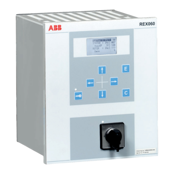
REX060 start up sequence GUID-63A15CD3-17B0-41DD-9611-8272DDA53137 v1 When the injection unit REX060 is energized, the ABB logotype is shown followed by current REX060 revision status. When the start up sequence is completed, the main menu (normal display content) is shown. The duration of the start up sequence is a few seconds. - Page 48 Section 4 1MRK 502 067-UEN B Starting up If needed, set the IP address for the IEDs. Set up the PC or workstation for a direct link (point-to-point), or Connect the PC or workstation to the LAN/WAN network. Configure the IED IP addresses in the PCM600 project for each IED to match the IP addresses of the physical IEDs.
- Page 49 1MRK 502 067-UEN B Section 4 Starting up IEC13000057-1-en.vsd IEC13000057 V1 EN-US Figure 4: Select: Search programs and files Type View network connections and click on the View network connections icon. Commissioning manual...
- Page 50 Section 4 1MRK 502 067-UEN B Starting up IEC13000058-1-en.vsd IEC13000058 V1 EN-US Figure 5: Click View network connections Right-click and select Properties. IEC13000059-1-en.vsd IEC13000059 V1 EN-US Figure 6: Right-click Local Area Connection and select Properties Select the TCP/IPv4 protocol from the list of configured components using this connection and click Properties.
- Page 51 1MRK 502 067-UEN B Section 4 Starting up IEC13000060-1-en.vsd IEC13000060 V1 EN-US Figure 7: Select the TCP/IPv4 protocol and open Properties IP address and Subnet mask if the front Select Use the following IP address and define IP address is not set to be obtained automatically by the IED, see port is used and if the Figure 8.
-
Page 52: Writing An Application Configuration To The Ied
Section 4 1MRK 502 067-UEN B Starting up The PC and IED must belong to the same subnetwork for this set-up to work. Setting up the PC to access the IED via a network The same method is used as for connecting to the front port. The PC and IED must belong to the same subnetwork for this set-up to work. -
Page 53: Checking Vt Circuits
1MRK 502 067-UEN B Section 4 Starting up Both the primary and the secondary sides must be disconnected from the line and the IED when plotting the excitation characteristics. If the CT secondary circuit earth connection is removed without the current transformer primary being de-energized, dangerous voltages may result in the secondary CT circuits. -
Page 54: Checking The Binary I/O Circuits
Section 4 1MRK 502 067-UEN B Starting up Verify that the contact sockets have been crimped correctly and that they are fully inserted by tugging on the wires. Never do this with current circuits in service. Current circuit Verify that the contacts are of current circuit type. Verify that the short circuit jumpers are located in the correct slots. -
Page 55: Configuring The Ied And Changing Settings
1MRK 502 067-UEN B Section 5 Configuring the IED and changing settings Section 5 Configuring the IED and changing settings Overview M11730-2 v6 The customer specific values for each setting parameter and a configuration file have to be available before the IED can be set and configured, if the IED is not delivered with a configuration. -
Page 56: Reconfiguring The Ied
Section 5 1MRK 502 067-UEN B Configuring the IED and changing settings The following parameter shall be set for every current transformer connected to the IED: Table 8: CT configuration Parameter description Parameter name Range Default Rated CT primary current in A CTPRIMn from 0 to 99999 3000... -
Page 57: Calibrating Injection Based Sensitive Rotor Earth Fault Protection
1MRK 502 067-UEN B Section 6 Calibrating injection based sensitive rotor earth fault protection Section 6 Calibrating injection based sensitive rotor earth fault protection Commissioning process GUID-837911AC-D87E-4E10-9D7D-B74A9F45A815 v1 The commissioning process utilizes the commissioning tool ICT. The instructions for the process cover installation, calibration, commissioning, monitoring and auditing for the sensitive rotor earth fault ROTIPHIZ function. - Page 58 Section 6 1MRK 502 067-UEN B Calibrating injection based sensitive rotor earth fault protection During the three steps described above a check is made that there are sufficient changes in the measured impedance in order to guarantee that there is no primary fault from the beginning or other problems due to the installation or calibration procedure.
-
Page 59: Launching Injection Commissioning Tool (Ict) And Performing The Installation
1MRK 502 067-UEN B Section 6 Calibrating injection based sensitive rotor earth fault protection Auditing In the auditing part installation, calibration and commissioning reports are stored. Launching injection commissioning tool (ICT) and performing the installation GUID-15CAE2A3-FA17-4119-9188-824C7F309D4B v3 Make sure you have not attached any additional impedance in parallel with the rotor circuit. -
Page 60: Performing Calibration
Section 6 1MRK 502 067-UEN B Calibrating injection based sensitive rotor earth fault protection Frequency found by Voltage and current signal Ffunction status field. Errors and the function staus and TRIP indication abnormalities are displayed in order to simplify trouble shooting. IEC11000045-1-en.vsd GUID-84947C77-215F-4007-AAC0-9433B8444396 V1 EN-US Figure 11:... - Page 61 1MRK 502 067-UEN B Section 6 Calibrating injection based sensitive rotor earth fault protection Stability region indicator bar IEC11000047-1-en.vsd GUID-3C7F0567-2367-46E4-9606-FCFC7408DAA0 V1 EN-US Figure 12: ICT calibration tab 1 including the stability region indicator bar Connect a calibration resistance between one pole of the field winding and ground; the value of the calibration resistance can be calculated as the impedance to ground of the rotor: ×...
- Page 62 Check the Calibration result field to make sure that all tests have been passed. 12.1. If a failure is indicated during one or more check(s), follow the instructions/tips provided by the ICT in the Calibration result field. 12.2. If these tips do not solve the issue, then contact ABB Support. Commissioning manual...
-
Page 63: Acquiring References
1MRK 502 067-UEN B Section 6 Calibrating injection based sensitive rotor earth fault protection IEC11000221-1-en.vsd IEC11000221 V1 EN-US Figure 13: ICT calibration tab 4 Before proceeding any further make sure that you have removed the short-circuit that was applied during the Step 3 of the calibration. To finish the calibration process, select the Submit to Parameter setting button. -
Page 64: Verifying Calibration
Section 6 1MRK 502 067-UEN B Calibrating injection based sensitive rotor earth fault protection To start reading the measurements, click the Start reading values from IED button in the ICT toolbar. ICT starts to read the selected viewed quantity from IED and plots values on the X/Y graph. - Page 65 1MRK 502 067-UEN B Section 6 Calibrating injection based sensitive rotor earth fault protection Selectable quantity for Currently used reference Selectable graph plotting update period Currently measured impedance and its Logger feature average IEC11000050-1-en.vsd GUID-DCE099B6-4DBA-4A52-9566-0E20B8AF7712 V1 EN-US Figure 15: Monitoring tab Set the graph update period to one second by typing 1 into the Graph update period field.
-
Page 66: Auditing
Section 6 1MRK 502 067-UEN B Calibrating injection based sensitive rotor earth fault protection Previously it was verified that the function measures correctly by applying known faults and observing the graph during monitoring. Besides measuring the fault size a trip indication is required when a large fault is measured to prevent that a damage to the generator occurs. -
Page 67: Editing Features In Graph
1MRK 502 067-UEN B Section 6 Calibrating injection based sensitive rotor earth fault protection • In the short cut menu, right click and select View report. • Click the View report button in the upper right corner of the auditing screen. •... -
Page 68: Logging Measurements To File
Section 6 1MRK 502 067-UEN B Calibrating injection based sensitive rotor earth fault protection IEC11000052-1-en.vsd GUID-261171B2-59CD-4248-B873-39A2BC3CD1F1 V1 EN-US Figure 18: Zooming via area selection of a part of the graph • Press PgUp key on the keyboard to zoom in and PgDn to zoom out. Cancel a zoom in the following ways: •... -
Page 69: Calibrating Injection Based 100% Stator Earth Fault Protection
1MRK 502 067-UEN B Section 7 Calibrating injection based 100% stator earth fault protection Section 7 Calibrating injection based 100% stator earth fault protection Commissioning process GUID-F7897190-70E1-4421-984B-8E0F06BB93CD v1 The commissioning process utilizes the commissioning tool ICT. The instructions for the process cover installation, calibration, commissioning, monitoring and auditing for the 100% stator earth fault STTIPHIZ function. - Page 70 Section 7 1MRK 502 067-UEN B Calibrating injection based 100% stator earth fault protection The injection is made to the faultless generator and the measured complex impedance is stored. A known resistance is connected between the generator neutral point (see Figure 19) and earth.
-
Page 71: Launching Injection Commissioning Tool (Ict) And Performing The Installation
1MRK 502 067-UEN B Section 7 Calibrating injection based 100% stator earth fault protection If a particular stable operating condition of the generator requires a dedicated reference impedance, it can be defined and saved by the Commissioning tab of ICT. STTIPHIZ . -
Page 72: Performing Calibration
Section 7 1MRK 502 067-UEN B Calibrating injection based 100% stator earth fault protection Button for Function selection Buttons for start/stop enable/disable dropdown menu reading from IED tripping IEC11000043-1-en.vsd GUID-3C378090-E33E-4AAA-8BBE-09FA872D9A87 V1 EN-US Figure 20: ICT toolbar Select the Installing tab if it was not already selected by default after the ICT was launched. - Page 73 1MRK 502 067-UEN B Section 7 Calibrating injection based 100% stator earth fault protection It is important that calibration steps (Step 1, Step 2 and Step 3) are performed in the proper order. If not, the calibration might fail. If readings are not stable during the step, a warning to repeat the step may be suggested;...
- Page 74 Check the Calibration result field to make sure that all tests have been passed. 12.1. If a failure is indicated during one or more check(s), follow the instructions/tips provided by the ICT in the Calibration result field. 12.2. If these tips do not solve the issue, then contact ABB Support. Commissioning manual...
-
Page 75: Acquiring References
1MRK 502 067-UEN B Section 7 Calibrating injection based 100% stator earth fault protection IEC11000048-2-en.vsd GUID-D024D8B7-45F3-42D1-AAA3-488A2996267B V1 EN-US Figure 23: ICT calibration tab 4 Before proceeding any further make sure that you have removed the short-circuit that was applied during calibration step 3. To finish the calibration process, select the Submit to Parameter setting button. -
Page 76: Verifying Calibration
Section 7 1MRK 502 067-UEN B Calibrating injection based 100% stator earth fault protection ICT starts to read the selected viewed quantity from IED and plots values on the X/Y graph. Measured absolute Measured absolute Floating average of the impedance ± standard impedance measured absolute deviation... - Page 77 1MRK 502 067-UEN B Section 7 Calibrating injection based 100% stator earth fault protection Selectable quantity for Currently used reference Selectable graph plotting update period Currently measured impedance and its Logger feature average IEC11000050-1-en.vsd GUID-DCE099B6-4DBA-4A52-9566-0E20B8AF7712 V1 EN-US Figure 25: Monitoring tab Set the graph update period to one second by typing 1 into the Graph update period field.
-
Page 78: Auditing
Section 7 1MRK 502 067-UEN B Calibrating injection based 100% stator earth fault protection Previously it was verified that the function measures correctly by applying known faults and observing the graph during monitoring. Besides measuring the fault size a trip indication is required when a large fault is measured to prevent that a damage to the generator occurs. -
Page 79: Editing Features In Graph
1MRK 502 067-UEN B Section 7 Calibrating injection based 100% stator earth fault protection • In the short cut menu, right click and select View report. • Click the View report button in the upper right corner of the auditing screen. •... -
Page 80: Logging Measurements To File
Section 7 1MRK 502 067-UEN B Calibrating injection based 100% stator earth fault protection IEC11000052-1-en.vsd GUID-261171B2-59CD-4248-B873-39A2BC3CD1F1 V1 EN-US Figure 28: Zooming via area selection of a part of the graph • Press PgUp key on the keyboard to zoom in and PgDn to zoom out. Cancel a zoom in the following ways: •... -
Page 81: Establishing Connection And Verifying The Spa/Iec Communication
1MRK 502 067-UEN B Section 8 Establishing connection and verifying the SPA/IEC communication Section 8 Establishing connection and verifying the SPA/IEC communication Entering settings M11735-2 v1 If the IED is connected to a monitoring or control system via the rear SPA/IEC port, the SPA/IEC port has to be set either for SPA or IEC use. -
Page 82: Verifying The Communication
Section 8 1MRK 502 067-UEN B Establishing connection and verifying the SPA/IEC communication When the setting is entered the IED restarts automatically. After the restart the selected IEC port operates as an IEC port. Set the slave number and baud rate for the rear IEC port. The slave number and baud rate can be found on the local HMI under Main menu/ Configuration/Communication/SLM configuration/Rear optical SPA-IEC-DNP port/ IEC60870–5–103... -
Page 83: Optical Budget Calculation For Serial Communication With Spa/Iec
1MRK 502 067-UEN B Section 8 Establishing connection and verifying the SPA/IEC communication Table 9: Max distances between IEDs/nodes glass < 1000 m according to optical budget plastic < 25 m (inside cubicle) according to optical budget Optical budget calculation for serial communication with SPA/IEC M11736-4 v2 Table 10:... -
Page 85: Establishing Connection And Verifying The Lon Communication
1MRK 502 067-UEN B Section 9 Establishing connection and verifying the LON communication Section 9 Establishing connection and verifying the LON communication Communication via the rear ports M12196-2 v1 9.1.1 LON communication M12196-4 v4 LON communication is normally used in substation automation systems. Optical fiber is used within the substation as the physical communication link. -
Page 86: The Lon Protocol
Section 9 1MRK 502 067-UEN B Establishing connection and verifying the LON communication Table 11: Specification of the fiber optic connectors Glass fiber Plastic fiber Cable connector ST-connector snap-in connector Cable diameter 62.5/125 m 1 mm Max. cable length 1000 m 10 m Wavelength 820-900 nm... - Page 87 1MRK 502 067-UEN B Section 9 Establishing connection and verifying the LON communication M11888-3 v4 The setting parameters for the LON communication are set via the local HMI. Refer to the technical manual for setting parameters specifications. The path to LON settings in the local HMI is Main menu/Configuration/Communication/SLM configuration/Rear optical LON port If the LON communication from the IED stops, caused by setting of illegal communication parameters (outside the setting range) or by another disturbance, it is possible to reset the...
-
Page 88: Optical Budget Calculation For Serial Communication With Lon
Section 9 1MRK 502 067-UEN B Establishing connection and verifying the LON communication Optical budget calculation for serial communication with LON M11737-4 v2 Table 16: Example Distance 1 km Distance10 m Glass Plastic Maximum attenuation -11 dB - 7 dB 4 dB/km multi mode: 820 nm - 62.5/125 um 4 dB 0.3 dB/m plastic: 620 nm - 1mm... -
Page 89: Section 10 Establishing Connection And Verifying The Iec 61850 Communication
1MRK 502 067-UEN B Section 10 Establishing connection and verifying the IEC 61850 communication Section 10 Establishing connection and verifying the IEC 61850 communication 10.1 Overview SEMOD172103-4 v6 The rear OEM ports are used for: • process bus (IEC 61850-9-2LE) communication •... -
Page 90: Verifying The Communication
Section 10 1MRK 502 067-UEN B Establishing connection and verifying the IEC 61850 communication 10.3 Verifying the communication SEMOD172108-24 v8 To verify that the communication is working a test/analyzing tool, for example ITT600, can be used. Verifying redundant IEC 61850-8-1 communication Ensure that the IED receives IEC 61850-8-1 data on both port AB and CD. -
Page 91: Section 11 Testing Ied Operation
1MRK 502 067-UEN B Section 11 Testing IED operation Section 11 Testing IED operation 11.1 Preparing for test IP336-1 v1 11.1.1 Requirements M11740-2 v8 IED test requirements: • Calculated settings • Application configuration diagram • Signal matrix (SMT) configuration • Terminal connection diagram •... -
Page 92: Preparing The Ied To Verify Settings
Section 11 1MRK 502 067-UEN B Testing IED operation This IED is designed for a maximum continuous current of four times the rated current. Please observe the measuring accuracy of the IED, the test equipment and the angular accuracy for both of them. Please consider the configured logic from the function block to the output contacts when measuring the operate time. -
Page 93: Activating The Test Mode
1MRK 502 067-UEN B Section 11 Testing IED operation Set and configure the function(s) before testing. Most functions are highly flexible and permit a choice of functional and tripping modes. The various modes are checked at the factory as part of the design verification. In certain cases, only modes with a high probability of coming into operation need to be checked when commissioned to verify the configuration and settings. -
Page 94: Connecting The Test Equipment To The Ied
Section 11 1MRK 502 067-UEN B Testing IED operation 11.4 Connecting the test equipment to the IED M11744-2 v7 Connect the test equipment according to the IED specific connection diagram and the needed input and output signals for the function under test. An example of a connection is shown in figure 30. -
Page 95: Verifying Analog Primary And Secondary Measurement
1MRK 502 067-UEN B Section 11 Testing IED operation function blocks can also be individually blocked to ensure that no events are reported to a remote station during the test. This is done by setting the parameter EvDisable to Yes . Any function is blocked if the corresponding setting in the local HMI under Main On , that is, the parameter menu/Test/Function test modes menu remains... -
Page 96: Forcing Of Binary I/O Signals For Testing
Section 11 1MRK 502 067-UEN B Testing IED operation • Verify operating levels (trip) and timers. • Verify alarm and blocking signals. • Use the disturbance handling tool in PCM600 to evaluate that the protection function has received the correct data and responded correctly (signaling and timing). •... -
Page 97: Enable Forcing Using Testmode Function Block
1MRK 502 067-UEN B Section 11 Testing IED operation 11.8.2.2 Enable forcing using TESTMODE function block GUID-DD17B7D6-516F-4561-9D30-906B968EAFE0 v1 • Use the TESTMODE function block, appropriately configured in PCM600/ACT. It may be convenient to control the input on mentioned component from, for example, an LHMI function key or similar during commissioning to quickly and easily enter IED test mode. -
Page 98: Forcing By Using Pcm600
Section 11 1MRK 502 067-UEN B Testing IED operation IEC15000022 V1 EN-US It is possible to power-cycle the IED in this state without losing the forcing states and values. This means that once a signal is forced, and the IED remains in IED test mode, the input or output will appear “frozen”... - Page 99 1MRK 502 067-UEN B Section 11 Testing IED operation Right click on the IED in the plant structure and select Signal Monitoring. List View tab. Click on the Forcing Session in the menu IED/Start Forcing . Click IEC15000023 V1 EN-US Start editing signal value for forcing on the tool bar.
-
Page 100: How To Undo Forcing Changes And Return The Ied To Normal Operation
Section 11 1MRK 502 067-UEN B Testing IED operation Regardless if the forcing changes are commited or canceled, the forcing is still active. Start editing signal value for forcing again. To force more signals, click the button 11.8.4 How to undo forcing changes and return the IED to normal operation GUID-00E2BAD8-A29E-4B9D-80E6-E12F59E019BD v1 Regardless of which input/output signals have been forced, all forced signals will return to... - Page 101 1MRK 502 067-UEN B Section 11 Testing IED operation PCM600 will revert all forced signals back to unforced and the real signal values will immediately take effect again. This may change both binary input values and output relay states and will undo any forcing done by using the LHMI.
-
Page 103: Section 12 Testing Functionality By Secondary Injection
1MRK 502 067-UEN B Section 12 Testing functionality by secondary injection Section 12 Testing functionality by secondary injection 12.1 Testing disturbance report 12.1.1 Introduction M17101-2 v6 The following sub-functions are included in the disturbance report function: • Disturbance recorder • Event list •... -
Page 104: Event Recorder (Er) And Event List (El)
Section 12 1MRK 502 067-UEN B Testing functionality by secondary injection Evaluation of the results from the disturbance recording function requires access to a PC either permanently connected to the IED or temporarily connected to the Ethernet port (RJ-45) on the front. The PCM600 software package must be installed in the PC. Disturbance upload can be performed by the use of PCM600 or by any third party tool with IEC 61850 protocol. -
Page 105: Verifying The Settings
1MRK 502 067-UEN B Section 12 Testing functionality by secondary injection 12.3.1.1 Verifying the settings SEMOD54284-51 v10 Go to Main menu/Test/Function test modes/Differential protection and make sure that Off and the restricted earth fault protection, low impedance function REFPDIF is set to that the four step residual overcurrent function EF4PTOC under Main menu/Test/ Off , since they are configured to the Function test modes/Current protection is set to... -
Page 106: Completing The Test
Section 12 1MRK 502 067-UEN B Testing functionality by secondary injection Connect single-phase or three-phase test set to inject the operating voltage. The injection is done across the measuring branch. The required trip and alarm voltage, as well as the used stabilizing resistance value must be set in the function. -
Page 107: Completing The Test
1MRK 502 067-UEN B Section 12 Testing functionality by secondary injection Check in the same way the function by injecting current in phases L2 and L3. Inject a symmetrical three-phase current and note the operate value. Connect the timer and set the current to twice the operate value. Switch on the current and note the operate time. -
Page 108: Completing The Test
Section 12 1MRK 502 067-UEN B Testing functionality by secondary injection 12.3.4.2 Completing the test SEMOD55252-118 v5 TestMode setting to Off . Continue to test another function or end the test by changing the Restore connections and settings to their original values, if they were changed for testing purposes. - Page 109 1MRK 502 067-UEN B Section 12 Testing functionality by secondary injection 120° R (Ohm/phase) 20° 40% of RLdFw 80% of RLdFw 0.5 x RFPP IEC05000368-3-en IEC05000368 V3 EN-US Figure 33: Distance protection characteristic with test points for phase-to-phase measurements Table 17: Test points for phase-to-phase loops L1-L2 (Ohm/Loop) Test point Reach...
- Page 110 Section 12 1MRK 502 067-UEN B Testing functionality by secondary injection Test point Reach Set value Comments 0.5 x X1 0.5 x R1 Only used when RLdFw > 0.5 x RFPP 0.5 x RFPP Table is used in conjunction with figure 33. X1+XN 120°...
-
Page 111: Measuring The Operating Limit Of Set Values
1MRK 502 067-UEN B Section 12 Testing functionality by secondary injection Test point Reach Value Comments RLdFw –0.1072 x RLdFw Exact: 0.4 x RFPE x tan (ArgDir=20°) 0.4 x RLdFw –0.8 x RLdFw tan(ArgDir=20°) 0.8 x RLdFw 0.17 x (2 x X1 + X0 Exact: 0.5 x (2 x X1 -0.36 x (2 x X1... -
Page 112: Completing The Test
Section 12 1MRK 502 067-UEN B Testing functionality by secondary injection Subject the IED to healthy normal load conditions for at least two seconds. Apply the fault condition to find the operating time for the phase-to-phase fault according to test point 12 in figure and table for zone 1. - Page 113 1MRK 502 067-UEN B Section 12 Testing functionality by secondary injection loop 60° ArgNegRes loop 50% of RLdFw RFFwPE IEC09000734-4-en.vsd IEC09000734 V4 EN-US Figure 35: Operating characteristic for phase selection function, forward direction single-phase faults Table 19: Test points for phase-to-earth loop L3-E (Ohm/loop) Test point Reach Value...
-
Page 114: Measuring The Operating Limit Of Set Values
Section 12 1MRK 502 067-UEN B Testing functionality by secondary injection phase ArgLd ArgNegRes 60° phase ArgDir 50% RLdFw 0.5·RFFwPP IEC09000735-3-en.vsd IEC09000735 V3 EN-US Figure 36: Operating characteristic for phase selection function, forward direction phase-to-phase faults Table 20: Test points for phase-to-phase loops L1–L2 (Ohm/phase) Test point Reach Value... -
Page 115: Completing The Test
1MRK 502 067-UEN B Section 12 Testing functionality by secondary injection Supply the IED with healthy conditions for at least two seconds. Apply the fault condition and slowly decrease the measured impedance to find the operate value for of the phase-to-earth loop L3, test point 1, according to figure 35. Compare the result of the measurement with the expected value according to table 19. -
Page 116: Phase-To-Phase Faults
Section 12 1MRK 502 067-UEN B Testing functionality by secondary injection 12.4.3.1 Phase-to-phase faults M14944-292 v8 ZAngPP Ohm/phase IEC07000009-4-en.vsd IEC07000009 V4 EN-US Figure 37: Proposed test points for phase-to-phase fault Table 21: Test points for phase-to-phase (ohms / phase) Test reach Value Comments... -
Page 117: Faulty Phase Identification With Load Encroachment Fmpspdis
1MRK 502 067-UEN B Section 12 Testing functionality by secondary injection ZAngPE Ohm/loop IEC07000010-4-en.vsd IEC07000010 V4 EN-US Figure 38: Proposed test points for phase-to-earth faults Table 22: Test points for phase-to-earth loops L1-L2 (Ohm/Loop) Test Reach Value Comments points ZPE · sin(ZAngPE) ZPE ·... - Page 118 Section 12 1MRK 502 067-UEN B Testing functionality by secondary injection Ensure that the maximum continuous current in an IED does not exceed four times its rated value, if the measurement of the operating characteristics runs under constant voltage conditions. The test procedure has to take into consideration that the shaped load encroachment characteristic is active.
- Page 119 1MRK 502 067-UEN B Section 12 Testing functionality by secondary injection X1+XN 120° R (Ohm/loop) 20° 40% of RLdFw 80% of RLdFw alt. 80% of RFPE RFPE (Load encroachment) IEC05000369-3-en.vsd IEC05000369 V3 EN-US Figure 40: Distance protection characteristic with test points for phase-to-earth measurements Table is used in conjunction with figure 40.
-
Page 120: Measuring The Operating Limit Of Set Values
Section 12 1MRK 502 067-UEN B Testing functionality by secondary injection Test point Reach Set value Comments 0.5 x X1 0.5 x R1 Only used when OperationLdCmp setting is 0 (Off) 0.5 x RFPP Table 24: Test points for phase-to-earth L3-E (Ohm/Loop) Test point Reach Value... -
Page 121: Measuring The Operating Time Of Distance Protection Zones
1MRK 502 067-UEN B Section 12 Testing functionality by secondary injection Subject the IED to healthy normal load conditions for at least two seconds. Apply the fault condition and slowly decrease the measured impedance to find the operating value of the phase-to-phase fault for zone 1 according to test point 1 in figure and table 23. - Page 122 Section 12 1MRK 502 067-UEN B Testing functionality by secondary injection loop 60° ArgNegRes loop 50% of RLdFw RFFwPE IEC09000734-4-en.vsd IEC09000734 V4 EN-US Figure 41: Operating characteristic for phase selection function, forward direction single-phase faults phase ArgLd ArgNegRes 60° phase ArgDir 50% RLdFw 0.5·RFFwPP...
-
Page 123: Measuring The Operating Limit Of Set Values
1MRK 502 067-UEN B Section 12 Testing functionality by secondary injection Test point Value Comments 0.85·[X1+XN] R≈0.491·(X1+XN)+RFFwPE 0.85·[X1+XN]·1/tan(60°)+RFFwPE 0.85·[X1+XN] -0.85·[X1+XN]· tan (AngNegRes-90°) RFFwPE·tan (ArgLd) RFFwPE -0.5·RLdFw·tan (ArgDir) 0.5·RLdFw The table showing test points for phase-to-earth loops is used together with figure 41. Table 26: Test points for phase-to-phase loops L1–L2 Test point Value... -
Page 124: Completing The Test
Section 12 1MRK 502 067-UEN B Testing functionality by secondary injection When the load encroachment characteristic is deliberately set very high in order not to have an influence, then the test points 2 and 5 can be replaced by test point 7. Repeat steps to find the operate value for the phase-to-phase fault in L1 —... - Page 125 1MRK 502 067-UEN B Section 12 Testing functionality by secondary injection 120° R (Ohm/phase) 20° 40% of RLdFw 80% of RLdFw 0.5 x RFPP IEC05000368-3-en IEC05000368 V3 EN-US Figure 43: Distance protection characteristic with test points for phase-to-phase measurements Table 27: Test points for phase-to-phase loops L1-L2 (Ohm/Loop) Test point Reach...
- Page 126 Section 12 1MRK 502 067-UEN B Testing functionality by secondary injection Test point Reach Set value Comments 0.5 x X1 0.5 x R1 0.5 x RFPP Table is used in conjunction with figure 43. X1+XN 120° R (Ohm/loop) 20° 40% of RLdFw 80% of RLdFw alt.
-
Page 127: Measuring The Operating Limit Of Set Values
1MRK 502 067-UEN B Section 12 Testing functionality by secondary injection Test point Reach Value Comments RLdFw –02143 x RLdFw Exact: 0.8 x RFPE x tan (ArgDir=20°) 0.8 x RLdFw –0.8 x RLdFw tan(ArgDir=20°) –0.8 x RLdFwd tan(ArgDir=20°) 0.8 x RLdFw 0.17 x (2 x X1 + X0 Exact: 0.5 x (2 x X1... -
Page 128: Completing The Test
Section 12 1MRK 502 067-UEN B Testing functionality by secondary injection Subject the IED to healthy normal load conditions for at least two seconds. Apply the fault condition to find the operating time for the phase-to-phase fault according to test point 12 in figure and table for zone 1. - Page 129 1MRK 502 067-UEN B Section 12 Testing functionality by secondary injection 120° R (Ohm/phase) 20° 40% of RLdFw 80% of RLdFw 0.5 x RFPP IEC05000368-3-en IEC05000368 V3 EN-US Figure 45: Distance protection characteristic with test points for phase-to-phase measurements Table 29: Test points for phase-to-phase loops L1-L2 (Ohm/Loop) Test point Reach Set value...
- Page 130 Section 12 1MRK 502 067-UEN B Testing functionality by secondary injection Test point Reach Set value Comments 0.5 x X1 0.5 x R1 0.5 x RFPP Table is used in conjunction with figure 45. X1+XN 120° R (Ohm/loop) 20° 40% of RLdFw 80% of RLdFw alt.
-
Page 131: Measuring The Operating Limit Of Set Values
1MRK 502 067-UEN B Section 12 Testing functionality by secondary injection Test point Reach Value Comments RLdFw –02143 x RLdFw Exact: 0.8 x RFPE x tan (ArgDir=20°) 0.8 x RLdFw –0.8 x RLdFw tan(ArgDir=20°) 0.8 x RLdFw 0.17 x (2 x X1 + X0 Exact: 0.5 x (2 x X1 -0.36 x (2 x X1... -
Page 132: Completing The Test
Section 12 1MRK 502 067-UEN B Testing functionality by secondary injection Subject the IED to healthy normal load conditions for at least two seconds. Apply the fault condition to find the operating time for the phase-to-phase fault according to test point 10 in figure and table for zone 1. -
Page 133: Verifying The Settings
1MRK 502 067-UEN B Section 12 Testing functionality by secondary injection X1OutFw X1InFw RLdOutRv RLdOutFw RLdInRv RLdInFw X1InRv X1OutRv IEC09000226_1_en.vsd IEC09000226 V1 EN-US Figure 47: Operating principle and characteristic of the power swing detection function (settings parameters in italic) Where: RLdOutFw ·... -
Page 134: Testing The Power Swing Detection Function Zmrpsb
Section 12 1MRK 502 067-UEN B Testing functionality by secondary injection Decrease the measured three-phase impedance slowly and observe the operation value for the signal ZOUT. Compare the operation value with the set value. Do the necessary change of the setting of the test equipment and repeat step and step for point 2, 3 and 4 according to figure 47. -
Page 135: Completing The Test
1MRK 502 067-UEN B Section 12 Testing functionality by secondary injection If the input I0CHECK is configured (connected to output signal STPE on FDPSPDIS or FRPSPDIS, the test of inhibit of ZMRPSB at earth-fault during power swing can be done in tR1 . - Page 136 Section 12 1MRK 502 067-UEN B Testing functionality by secondary injection Zone 1 Zone 2 X’ Pole slip impedance movement Zone 2 TripAngle Zone 1 WarnAngle IEC07000099_2_en.vsd IEC07000099 V2 EN-US Figure 48: Setting of the pole slip protection PSPPPAM Commissioning manual...
-
Page 137: Completing The Test
1MRK 502 067-UEN B Section 12 Testing functionality by secondary injection Imin > 0.10 IBase Umax < 0.92 UBase START 0.2 £ f(Ucos) £ 8Hz d ³ StartAngle ZONE1 Z cross line ZA - ZC ZONE2 Z cross line ZC - ZB Counter b a ³... -
Page 138: Verifying The Settings
Section 12 1MRK 502 067-UEN B Testing functionality by secondary injection 12.4.11.1 Verifying the settings GUID-708C4033-3111-481F-9868-FF207C18C9F9 v1 The test of the out-of-step protection function is made to verify that the trip is issued if the following events happen. • the impedance, seen by the function, enters the lens characteristic from one side and leaves it from the opposite side TripAngle and tBreaker •... - Page 139 1MRK 502 067-UEN B Section 12 Testing functionality by secondary injection 2 5 8367 20918 × × Base (Equation 3) EQUATION14043 V1 EN-US ReachZ1 defines the boundary between zone 1 and zone 2; it is expressed in The parameter ForwardX . If the setting of ReachZ1 = 12% , then corresponding percent of the parameter primary value of the reactance is ReachZ...
- Page 140 Section 12 1MRK 502 067-UEN B Testing functionality by secondary injection The previous calculations are in primary values. They are transferred to secondary values to perform injections by a test set. Primary values are transferred to secondary values by taking into account the CT ratio and the VT ratio (respectively 9000/1 A and 13.8/0.1 kV in the example).
-
Page 141: Test Of Point Re
1MRK 502 067-UEN B Section 12 Testing functionality by secondary injection • 49.5 Hz for the test as generator in the quadrant 1 and 2 of the R-X plane • 50.5 Hz for the test as generator in the quadrant 3 and 4 of the R-X plane When the trajectory of the impedance, that is seen by the protection function, traverses the lens characteristic then a pole slipping is detected. - Page 142 Section 12 1MRK 502 067-UEN B Testing functionality by secondary injection ForwardX 59 33 arctan arctan 82. . 14° ∠ = = ForwardR 8 19 (Equation 18) EQUATION14058 V1 EN-US frequency of V = 50 Hz 10459...
- Page 143 1MRK 502 067-UEN B Section 12 Testing functionality by secondary injection VT s 1 1 11931 95 1 × × × × t FwdZ 13 8 VT p (Equation 23) EQUATION14057 V1 EN-US ForwardX 59 33 arctan arctan 82.
- Page 144 Section 12 1MRK 502 067-UEN B Testing functionality by secondary injection frequency of = 50 Hz • Check that the service values (VOLTAGE, CURRENT, R(%), X(%) ) are according to the injected quantities and that ROTORANG is close to 3.14 rad. For this particular injection the service values are: •...
-
Page 145: Test Of The Boundary Between Zone 1 And Zone 2, Which Is Defined By The Parameter Reachz1
1MRK 502 067-UEN B Section 12 Testing functionality by secondary injection 10459 1 162 × × 9000 (Equation 36) EQUATION14062 V1 EN-US ∠I = 180º frequency of I = 49.5 Hz Expected result: start of the protection function and trip in zone 2, when trip conditions are fulfilled. - Page 146 Section 12 1MRK 502 067-UEN B Testing functionality by secondary injection Note that these values identify a point inside the lens characteristic, in the Zone 2, that is close to the boundary between zone 1 and zone 2. The START is issued, but no TRIP is performed. Execution of the dynamic test GUID-53964189-42E4-4C4B-BFCD-64888BA938EF v1 The test may be performed by using two states of a sequence tool that is a basic feature of...
- Page 147 1MRK 502 067-UEN B Section 12 Testing functionality by secondary injection The trajectory of the impedance traverses the lens characteristic in zone 1 GUID-12F82DD8-A4CE-48C9-944B-0CF3B3F6C9F9 v1 Preliminary steady state test at 50 Hz GUID-AA953F5F-2389-4F05-8BBD-D8DC9AF3B0E4 v1 • Go to Main menu/Test/Function status/Impedance protection/OutOfStep(78,Ucos)/ OOSPPAM(78,Ucos):1/Outputs to check the available service values of the function block OOSPPAM.
-
Page 148: Test Of The Point Se (R Rvsr , X Rvsx )
Section 12 1MRK 502 067-UEN B Testing functionality by secondary injection VT s 0 9 1435 9 36 × × × × t RZ 13 8 VT p (Equation 51) EQUATION14066 V1 EN-US ForwardX 59 33 arctan arctan 82. - Page 149 1MRK 502 067-UEN B Section 12 Testing functionality by secondary injection VT s 0 9 5899 38 47 × × × × t RvsZ 13 8 VT p (Equation 57) EQUATION14067 V1 EN-US æ ö æ ö ReverseX 29.60 Ð °...
- Page 150 Section 12 1MRK 502 067-UEN B Testing functionality by secondary injection • State 2: main test step. Define the following three-phase symmetrical quantities (the phase angle is related to phase L1): VT s 0 9 5899 38 47 × × ×...
- Page 151 1MRK 502 067-UEN B Section 12 Testing functionality by secondary injection 10459 1 162 × × 9000 (Equation 70) EQUATION14062 V1 EN-US ∠ = 0º frequency of = 50 Hz • Check that the service values (VOLTAGE, CURRENT, R(%), X(%)) are according to the injected quantities and that ROTORANG is close to 0 rad.
-
Page 152: Automatic Switch Onto Fault Logic Zcvpsof
Section 12 1MRK 502 067-UEN B Testing functionality by secondary injection 10459 1 162 × × 9000 (Equation 75) EQUATION14059 V1 EN-US ∠I = 0º frequency of I = 50 Hz 10459 1 162 × × 9000 (Equation 76) EQUATION14062 V1 EN-US ∠I = 180º... -
Page 153: Activating Zcvpsof Externally
1MRK 502 067-UEN B Section 12 Testing functionality by secondary injection ZCVPSOF is activated either by the external input BC, or by the internal DLD. FUFSPVC is done with a pre-fault condition where the phase voltages and currents are at zero. A reverse three- phase fault with zero impedance and a three-phase fault with an impedance corresponding to the whole line is applied. -
Page 154: Verifying The Settings
Section 12 1MRK 502 067-UEN B Testing functionality by secondary injection 12.4.13.1 Verifying the settings SEMOD158873-39 v3 The test is done by means of injection of three phase current and three phase voltage from a modern test device. This test device shall be able to give voltage and current corresponding to the set apparent impedance. -
Page 155: Completing The Test
1MRK 502 067-UEN B Section 12 Testing functionality by secondary injection 12.4.13.2 Completing the test SEMOD158873-46 v3 TestMode setting to Off . Continue to test another function or end the test by changing the Restore connections and settings to their original values, if they were changed for testing purposes. -
Page 156: Under Impedance Protection For Generator Zgvpdis
Section 12 1MRK 502 067-UEN B Testing functionality by secondary injection 12.4.15 Under impedance protection for Generator ZGVPDIS GUID-F882501B-6A03-4409-BF70-DE1CF09E5541 v3 Prepare the IED for verification of settings. Values of the logical signals for ZGVPDIS are available on the local HMI under Main menu/ Tests/Function status/Impedance/ZGVPDIS (21G, Z<)/1:ZGVPDIS:ZGVPDIS. - Page 157 1MRK 502 067-UEN B Section 12 Testing functionality by secondary injection Test points Z1Fwd · sin( LineAngle ) Z1Fwd · cos( LineAngle ) Z1Fwd - Z1Rev / 2) · sin( LineAngle )) Z1Fwd / 2 · (1 + cos( LineAngle ) + Z1Rev / 2 · (1 LineAngle )) –...
-
Page 158: Completing The Test
Section 12 1MRK 502 067-UEN B Testing functionality by secondary injection Change the magnitude and angle of phase-to-phase voltage to achieve impedances at test points P1, P2, P3 and P4. For each test point, observe that the output signals, START and STZx are activated (where x is 2 or 3 depending on selected zone). -
Page 159: Testing
1MRK 502 067-UEN B Section 12 Testing functionality by secondary injection 12.4.16.1 Testing SEMOD158692-13 v2 The protection function uses injection of an ac voltage to the generator field circuit. The COMBIFLEX voltage injection unit RXTTE4, Part No 1MRK 002 108-AB contains a voltage transformer with a primary winding for connection to 120 or 230 V, 50 or 60 Hz supply voltage. -
Page 160: Completing The Test
Section 12 1MRK 502 067-UEN B Testing functionality by secondary injection Close the switch to the station earth and check that the trip from the rotor earth fault will be given after the set delay time. Open the switch to the station earth and check that the trip signal resets instantaneously. -
Page 161: Four Step Phase Overcurrent Protection 3-Phase Output Oc4Ptoc
1MRK 502 067-UEN B Section 12 Testing functionality by secondary injection 12.5.2 Four step phase overcurrent protection 3-phase output OC4PTOC SEMOD56287-67 v7 Prepare the IED for verification of settings as outlined in section "Requirements" section "Preparing for test" in this chapter. 12.5.2.1 Verifying the settings SEMOD56287-72 v9... -
Page 162: Completing The Test
Section 12 1MRK 502 067-UEN B Testing functionality by secondary injection Reverse the direction of the injected current and check that the protection does not operate. 2 out of 3 or 3 out of 3 currents for operation is chosen: Check that the function will not operate with current in one phase only. -
Page 163: Four Step Non-Directional Earth Fault Protection
1MRK 502 067-UEN B Section 12 Testing functionality by secondary injection Connect the injection current to terminals L1 and neutral. Set the injected polarizing voltage slightly larger than the set minimum polarizing voltage (default 5% of Ur) and set the injection current to lag the voltage by an angle equal to the AngleRCA ), if the forward directional function is set reference characteristic angle ( selected. -
Page 164: Completing The Test
Section 12 1MRK 502 067-UEN B Testing functionality by secondary injection Connect the test set for injection of three-phase currents and voltages to the appropriate CT and VT inputs of the IED. Inject pure negative sequence current, that is, phase currents with exactly same magnitude, reversed sequence and exactly 120°... -
Page 165: Measuring The Operate And Time Limit For Set Values
1MRK 502 067-UEN B Section 12 Testing functionality by secondary injection IED test set TRIP IEC09000021-2-en.vsd IEC09000021 V2 EN-US Figure 56: Principle connection of the test set Values of the logical signals belonging to the sensitive directional residual overcurrent and power protection are available on the local HMI under Main menu/Test/Function status/ Current protection/SensDirResOvCurr(67N,IN>)/SDEPSDE(67N,IN>):x 12.5.6.1... - Page 166 Section 12 1MRK 502 067-UEN B Testing functionality by secondary injection The expected value depends on whether definite or inverse time was selected. Set the polarizing voltage to zero and increase until the boolean output signal UNREL is activated, which is visible in the Application Configuration in PCM600 when the IED is in UNRel>...
- Page 167 1MRK 502 067-UEN B Section 12 Testing functionality by secondary injection RCADir = 0º Operate area Instrument transformer angle error RCAcomp Characteristic after angle compensation (to prot) (prim) IEC06000651-3-en.vsd IEC06000651 V3 EN-US Figure 58: Explanation of RCAcomp Operation mode 3I ·...
- Page 168 Section 12 1MRK 502 067-UEN B Testing functionality by secondary injection Operation mode 3I and φ SEMOD175060-87 v8 UNRel> and set the phase angle between voltage and Set the polarizing voltage to 1.2 · RCADir ). Note that the current lagging the voltage. current to the set characteristic angle ( Inject current until the function picks up, and make sure that the operate current is equal INDir>...
-
Page 169: Completing The Test
1MRK 502 067-UEN B Section 12 Testing functionality by secondary injection tINNonDir or inverse time was The expected value depends on whether definite time selected. Off . Continue to test another function or complete the test by setting the test mode to Residual overvoltage release and protection SEMOD175060-131 v6 Procedure... -
Page 170: Completing The Test
Section 12 1MRK 502 067-UEN B Testing functionality by secondary injection Connect symmetrical three-phase currents to the appropriate current terminals of the IED. Tau1 ) and Time Constant 2 ( Tau2 ) temporarily to 1 minute. Set the Time constant 1 ( Set the three-phase injection currents slightly lower than the set operate value of stage IBase1 , increase the current in phase L1 until stage IBase1 operates and note the operate value. -
Page 171: Checking The Phase Current Operate Value, Ip
1MRK 502 067-UEN B Section 12 Testing functionality by secondary injection 2 out of 4 the phase current setting, IP> can be checked by single-phase injection At mode where the return current is connected to the summated current input. The value of residual IP>... -
Page 172: Verifying The Back-Up Trip Mode
Section 12 1MRK 502 067-UEN B Testing functionality by secondary injection RetripMode = Retrip Off . Apply the fault condition, including start of CCRBRF, well above the set current value. Verify that no re-trip, but back-up trip is achieved after set time. RetripMode = CB Pos Check Checking the re-trip with current check, M12104-48 v6... -
Page 173: Verifying Instantaneous Back-Up Trip At Cb Faulty Condition
1MRK 502 067-UEN B Section 12 Testing functionality by secondary injection Apply the fault condition, including start of CCRBRF, with at least one-phase current below set IP> and residual (earth fault) above set IN> . The current may be arranged by IP>... -
Page 174: Completing The Test
Section 12 1MRK 502 067-UEN B Testing functionality by secondary injection FunctionMode = Current&Contact . Apply input signal for CB closed to the relevant input or inputs CBCLDL1 (2 or 3). Apply the fault condition with input signal(s) for start of CCRBRF. The value of current I>BlkCont . -
Page 175: Checking The Phase Current Operate Value Ip
1MRK 502 067-UEN B Section 12 Testing functionality by secondary injection Checking the phase current operate value IP> 12.5.10.1 SEMOD128582-25 v6 Procedure IP> . Apply the fault condition, including START of CCSRBRF, with a current below set Repeat the fault condition and increase the current in steps until a trip occurs. IP>... -
Page 176: Verifying The Back-Up Trip Mode
Section 12 1MRK 502 067-UEN B Testing functionality by secondary injection RetripMode = No CBPos Check . Apply the fault condition, including START of CCSRBRF, well above the set current value. t1 , and back-up trip after time t2 . Verify that re-trip is achieved after set time Apply the fault condition, including START of CCSRBRF, with current below set current value. -
Page 177: Verifying The Function Mode Curr&Cont Check
1MRK 502 067-UEN B Section 12 Testing functionality by secondary injection Curr&Cont Check 12.5.10.7 Verifying the function mode SEMOD128582-207 v3 FunctionMode = Current&Contact is selected. It is suggested to make To be made only when the tests in one phase only, or at three-phase trip applications for just three-phase tripping. Checking the case with fault current above set value SEMOD128582-211 v6 FunctionMode = Current . -
Page 178: Measuring The Operate Limit Of Set Values
Section 12 1MRK 502 067-UEN B Testing functionality by secondary injection Logical signals for STBPTOC protection are available on the local HMI underMain menu/ Settings/Setting group N/Current protection/Stub(PTOC,50STB)/STBPTOC:x 12.5.11.1 Measuring the operate limit of set values M14922-6 v8 Check that the input logical signals BLOCK and RELEASE and the output logical signal TRIP are all logical zero. -
Page 179: Completing The Test
1MRK 502 067-UEN B Section 12 Testing functionality by secondary injection Activate the BLOCK binary input. Activate EXTPDIND binary input. NO TRIP signal should appear. Reset both BLOCK and EXTPDIND binary inputs. selection = ContSel setting equals Pole If Internal detection logic Contact function position from auxiliary contacts. - Page 180 Section 12 1MRK 502 067-UEN B Testing functionality by secondary injection Table 32: Calculation modes Mode Set value: Formula used for complex power calculation L1, L2, L3 × × × (Equation 80) EQUATION1697 V1 EN-US Arone × × (Equation 81) EQUATION1698 V1 EN-US PosSeq = ×...
-
Page 181: Completing The Test
1MRK 502 067-UEN B Section 12 Testing functionality by secondary injection 12.5.13.2 Completing the test SEMOD175027-15 v4 TestMode setting to Off . Continue to test another function or end the test by changing the Restore connections and settings to their original values, if they were changed for testing purposes. -
Page 182: Completing The Test
Section 12 1MRK 502 067-UEN B Testing functionality by secondary injection Check that the input logical signal BLOCK to the BRCPTOC function block is logical zero and note on the local HMI that the output signal TRIP from the BRCPTOC function block is equal to the logical 0. -
Page 183: Completing The Test
1MRK 502 067-UEN B Section 12 Testing functionality by secondary injection phase short-circuit gives a negative sequence current of a magnitude: magnitude = (1/√3) · fault current. Increase the injected current and note the value at which the step 1 of the function operates. -
Page 184: Accidental Energizing Protection For Synchronous Generator Aegpvoc
Section 12 1MRK 502 067-UEN B Testing functionality by secondary injection 12.5.17 Accidental energizing protection for synchronous generator AEGPVOC GUID-6E141754-28E5-408D-955F-899720BA59E0 v2 Prepare the IED for verification of settings outlined in section "Requirements" and section "Preparing for test" in this chapter. 12.5.17.1 Verifying the settings GUID-B834BA0F-E8CE-4B08-9FCE-B6D2813D3197 v3... - Page 185 1MRK 502 067-UEN B Section 12 Testing functionality by secondary injection StartCurr VDepFact IBase × × × CTprim (Equation 89) IECEQUATION2432 V1 EN-US UBase ≤ Restrain voltage ≤ UHighLimit / Second part of the characteristic (25% of 100* UBase ), valid when setting parameter VDepMode = Slope : ...
- Page 186 Section 12 1MRK 502 067-UEN B Testing functionality by secondary injection is slightly above 0.25 A on the secondary side. The corresponding trip signals TROC and TRIP will be activated after the pre-set time delay has expired. Decrease the current IL1 slowly and note the reset value. Repeat steps 4 and 5 applying voltages that are related to the second and the last section of the characteristic;...
-
Page 187: Completing The Test
1MRK 502 067-UEN B Section 12 Testing functionality by secondary injection If the VRPVOC function is used as an overcurrent protection with undervoltage seal-in, it is necessary to first inject sufficient current to activate the STOC signal before the under-voltage step is allowed to operate. -
Page 188: Completing The Test
Section 12 1MRK 502 067-UEN B Testing functionality by secondary injection Set the injected current to 226% of IBase, switch on the current and check operate time of the trip, 10 s. Switch off the current. Finally check that start and trip information is stored in the event menu. 12.5.19.2 Completing the test GUID-F79CE91E-7F07-45F4-8CDC-D7426CA9CBEA v2... -
Page 189: Voltage Protection
1MRK 502 067-UEN B Section 12 Testing functionality by secondary injection purposes. Make sure that all built-in features for this function, which shall be in operation, are enabled and with correct settings. 12.6 Voltage protection SEMOD53540-1 v1 12.6.1 Two step undervoltage protection UV2PTUV M13796-2 v6 Prepare the IED for verification of settings as outlined in section "Requirements"... -
Page 190: Completing The Test
Section 12 1MRK 502 067-UEN B Testing functionality by secondary injection Settable time multiplier of the function for step 1 Measured voltage U1< Set start voltage for step 1 For example, if the measured voltage jumps from the rated value to 0.8 times the set start voltage level and time multiplier k1 is set to 0.05 s (default value), then the TR1 and TRIP signals operate at a time equal to 0.250 s ±... -
Page 191: Extended Testing
1MRK 502 067-UEN B Section 12 Testing functionality by secondary injection Check the inverse time delay by injecting a voltage corresponding to 1.2 × U1>. Repeat the test to check the inverse time characteristic at different over-voltage levels. Repeat the above-described steps for Step 2 of the function. 12.6.2.2 Extended testing GUID-BE4B4A36-CCEE-4020-B7DC-6A83A43D11F5 v2... -
Page 192: Completing The Test
Section 12 1MRK 502 067-UEN B Testing functionality by secondary injection 12.6.3.2 Completing the test SEMOD54358-38 v4 TestMode setting to Off . Continue to test another function or end the test by changing the Restore connections and settings to their original values, if they were changed for testing purposes. -
Page 193: Check Of Undervoltage Levels
1MRK 502 067-UEN B Section 12 Testing functionality by secondary injection 12.6.5.1 Check of undervoltage levels SEMOD175258-71 v2 BlkDiffAtULow = Yes . This test is relevant if the setting Check of U1Low SEMOD175258-75 v3 Procedure Connect voltages to the IED according to valid connection diagram and figure 60. UDTrip , U1Low and U2Low to the U1 Apply voltage higher than the highest set value of three-phase inputs and to one phase of the U2 inputs according to figure 60. -
Page 194: Check Of Voltage Differential Trip And Alarm Levels
Section 12 1MRK 502 067-UEN B Testing functionality by secondary injection IEC07000107-1-en.vsd IEC07000107 V2 EN-US Figure 61: Connection of the test set to the IED for test of U2 block level where: is three-phase voltage group1 (U1) is three-phase voltage group2 (U2) UDTrip , U1Low and U2Low to the U1 Apply voltage higher than the highest set value of three-phase inputs and to one phase of the U2 inputs according to figure 61. -
Page 195: Check Of Trip And Trip Reset Timers
1MRK 502 067-UEN B Section 12 Testing functionality by secondary injection IEC07000108-1-en.vsd IEC07000108 V2 EN-US Figure 62: Connection of the test set to the IED for test of alarm levels, trip levels and trip timer where: is three-phase voltage group1 (U1) is three-phase voltage group2 (U2) Apply 1.2 ·... -
Page 196: Final Adjustment Of Compensation For Vt Ratio Differences
Section 12 1MRK 502 067-UEN B Testing functionality by secondary injection tTrip . Check the measured time by comparing it to the set trip time Increase the voltage until START signal resets. Measure the time from reset of START signal to reset of TRIP signal. tReset . -
Page 197: Verifying Settings
1MRK 502 067-UEN B Section 12 Testing functionality by secondary injection en07000127.vsd IEC07000127 V1 EN-US Figure 63: Typical phasor diagram for third harmonic voltages for healthy machine Inject the following voltages: U = 15 V, U = 5 V and the angle between the voltages = 180°. -
Page 198: Completing The Test
Section 12 1MRK 502 067-UEN B Testing functionality by secondary injection terminal side of the generator) and ANGLE (the angle between the third-harmonic voltage phasors U and U ). The value of E3 should be close to the following value: ×... -
Page 199: Completing The Test
1MRK 502 067-UEN B Section 12 Testing functionality by secondary injection Simultaneously disconnect all the three-phase voltages from the IED. No TRIP signal should appear. Reset the VTSU binary input. tRestore time. Inject the measured voltages at rated values for at least set Activate the BLOCK binary input. -
Page 200: Completing The Test
Section 12 1MRK 502 067-UEN B Testing functionality by secondary injection StartFrequency . Slowly decrease the frequency of the applied voltage, to a value below Check that the START signal does not appear. tDelay , make sure that the TRIP signal does not appear. Wait for a time corresponding to 12.7.1.2 Completing the test... -
Page 201: Rate-Of-Change Frequency Protection Sapfrc
1MRK 502 067-UEN B Section 12 Testing functionality by secondary injection 12.7.3 Rate-of-change frequency protection SAPFRC M16256-2 v6 Prepare the IED for verification of settings as outlined in section "Requirements" section "Preparing for test" in this chapter. 12.7.3.1 Verifying the settings M16256-8 v1 Verification of START value and time delay to operate M16256-10 v5... - Page 202 Section 12 1MRK 502 067-UEN B Testing functionality by secondary injection Compare the operate value to the set frequency high limit value. Decrease the frequency of the applied voltage until it crosses the frequency low limit and the START signal disappears. Check that the FREQOK signal disappears.
-
Page 203: Completing The Test
1MRK 502 067-UEN B Section 12 Testing functionality by secondary injection 10. Check that the START signal reappears. 11. Slowly increase the positive-sequence voltage of the injected voltage above the UHighLimit value until the START signal disappears. 12. Compare the reset value to the set voltage high limit value. 12.7.4.2 Completing the test GUID-83C3F041-9553-4804-9A39-B3E46A5C9AE6 v2... -
Page 204: Overcurrent Feature With Current Restraint
Section 12 1MRK 502 067-UEN B Testing functionality by secondary injection Check that TRIP and START contacts operate according to the configuration logic. Release the blocking of the high set stage and check the operate and reset value and the time delay for the high set stage in the same way as for the low set stage. -
Page 205: Over/Undervoltage Feature
1MRK 502 067-UEN B Section 12 Testing functionality by secondary injection Connect the test set for injection of three-phase currents and three-phase voltages to the appropriate current and voltage terminals of the IED. Inject current(s) and voltage(s) in a way that relevant measured (according to setting CurrentInput and VoltageInput ) currents and voltages are created from the parameter test set. -
Page 206: Completing The Test
Section 12 1MRK 502 067-UEN B Testing functionality by secondary injection Check the input circuits and the operate value of the IMinOp current level detector by injecting current, one phase at a time. Check the phase current blocking function for all three phases by injecting current, one phase at a time. -
Page 207: Measuring The Operate Value For The Negative Sequence Function
1MRK 502 067-UEN B Section 12 Testing functionality by secondary injection 12.9.2.2 Measuring the operate value for the negative sequence function M1405-46 v11 Measure the operate value for the negative sequence function, if included in the IED. Simulate normal operating conditions with the three-phase currents in phase with their corresponding phase voltages and with all of them equal to their rated values. -
Page 208: Measuring The Operate Value For The Dead Line Detection Function
Section 12 1MRK 502 067-UEN B Testing functionality by secondary injection × (Equation 111) IEC00000276 V1 EN-US Where: and U are the measured phase voltages IEC00000275 V1 EN-US Compare the result with the set value of the zero-sequence operating voltage (consider that the set value 3U0>... -
Page 209: Completing The Test
1MRK 502 067-UEN B Section 12 Testing functionality by secondary injection The BLKU, BLKZ and 3PH signals should reset, if activated, see step and 2. Change the voltages and currents in all three phases simultaneously. DU> and the current change must The voltage change must be higher than the set value DI<... -
Page 210: Completing The Test
Section 12 1MRK 502 067-UEN B Testing functionality by secondary injection After more than 5 seconds increase the measured voltage back to the value slightly below USealIn level. MAINFUF signal should not reset. USealIn until MAINFUF signal Slowly increase measured voltage to the value slightly above resets. -
Page 211: Testing The Synchronizing Function
1MRK 502 067-UEN B Section 12 Testing functionality by secondary injection Test UMeasure U-Bus U3PBB1 Ph/N equipment Ph/Ph Input Phase L1,L2,L3 L12,L23,L31 UMeasure U-Line Ph/N U3PLN1 Ph/Ph Input Phase L1,L2,L3 L12,L23,L31 IEC05000480-4-en.vsd IEC05000480 V4 EN-US Figure 64: General test connection with three-phase voltage connected to the line side U-Bus1 Test UMeasure... -
Page 212: Testing The Synchrocheck Check
Section 12 1MRK 502 067-UEN B Testing functionality by secondary injection Testing the frequency difference M2377-116 v10 The frequency difference test should verify that operation is achieved when the frequency FreqDiffMax and above set value of difference between bus and line is less than set value of FreqDiffMin . - Page 213 1MRK 502 067-UEN B Section 12 Testing functionality by secondary injection Testing the phase angle difference M2377-215 v8 The phase angle differences PhaseDiffM and PhaseDiffA respectively are set to their final settings and the test should verify that operation is achieved when the phase angle difference is lower than this value both leading and lagging.
-
Page 214: Testing The Energizing Check
Section 12 1MRK 502 067-UEN B Testing functionality by secondary injection Testing the reference voltage M2377-249 v5 Use the same basic test connection as in figure 64. The voltage difference between the voltage connected to U-Bus and U-Line should be 0%, so that the AUTOSYOK and MANSYOK outputs are activated first. -
Page 215: Testing The Voltage Selection
1MRK 502 067-UEN B Section 12 Testing functionality by secondary injection Verify the local HMI settings AutoEnerg or ManEnerg to be Both . GblBaseSelLine to the U-Line and a single-phase Apply a single-phase voltage of 30% GblBaseSelBus to the U-Bus. voltage of 100% tAutoEnerg Check that the AUTOENOK and MANENOK outputs are activated after set... - Page 216 Section 12 1MRK 502 067-UEN B Testing functionality by secondary injection Testing the voltage selection for 1 1/2 CB arrangements GUID-12E7DA63-FE04-4C83-9BA6-34818C510DB8 v4 At test of the SESRSYN function for a 1½ CB diameter the following alternative voltage inputs can be used for the three SESRSYN (SESRSYN 1, SESRSYN 2, SESRSYN 3) functions. These three SESRSYN functions can either be in one, two or three different IEDs.
-
Page 217: Completing The Test
1MRK 502 067-UEN B Section 12 Testing functionality by secondary injection WA1_QA1 WA2_QA1 (SESRSYN 1) (SESRSYN 3) TIE_QA1 (SESRSYN 2) LINE1_QB9 LINE2_QB9 LINE1 LINE2 IEC11000274-3-en.vsd IEC11000274 V3 EN-US Figure 67: Objects used in the voltage selection logic 12.10.1.5 Completing the test M2377-1042 v5 TestMode setting to Off . - Page 218 Section 12 1MRK 502 067-UEN B Testing functionality by secondary injection The automatic voltage control for tap changer, parallel control TR8ATCC, if installed, may be set to operate in Master Follower (MF) mode, or Minimise Circulating Current (MCC) mode. The commissioning tests for each parallel control mode are addressed separately in the following procedure.
-
Page 219: Secondary Test
1MRK 502 067-UEN B Section 12 Testing functionality by secondary injection During the installation and commissioning, the behavior of the voltage control functions for different tests may be governed by a parameter group, available on the local HMI under Main menu/Settings/IED Settings/Control/ TransformerVoltageControl(ATCC,90)/TR1ATCC:x/TR8ATCC:x. -
Page 220: Check The Normal Voltage Regulation Function
Section 12 1MRK 502 067-UEN B Testing functionality by secondary injection Confirm Transformer Tap Control = On and Transformer Voltage Control = On • Direct tap change control Main menu/Settings/IED Settings/Control/TransformerTapChanger(YLTC,84)/ TCMYLTC:x/TCLYLTC:x/Operation • Automatic transformer voltage control Main menu/Settings/IED Settings/Control/TransformerVoltageControl(ATCC,90)/ TR1ATCC:x/TR8ATCC:x/General/Operation •... -
Page 221: Check The Upper And Lower Busbar Voltage Limit
1MRK 502 067-UEN B Section 12 Testing functionality by secondary injection alarm, total or automatic block of the voltage control function to be displayed on the local HMI. Ublock and confirm the response of the voltage control Apply a voltage slightly below function. -
Page 222: Parallel Voltage Regulation
Section 12 1MRK 502 067-UEN B Testing functionality by secondary injection (Equation 115) EQUATION2080 V3 EN-US where: = Re(I ) + jlm(I ) are complex phase quantities When all secondary phase-to-earth voltages are available, use the positive-sequence components of voltage and current. By separation of real and imaginary parts: ×... - Page 223 1MRK 502 067-UEN B Section 12 Testing functionality by secondary injection For the transformers connected in the parallel group, confirm that OperationPAR is set to MF . For parallel operation, it is also recommended to confirm for parallel group membership, TnRXOP in the local HMI under Main menu/Settings/Setting group N/ defined by setting Control/TransformerVoltageControl(ATCC,90)/TR8ATCC:x/ParCtrl...
- Page 224 Section 12 1MRK 502 067-UEN B Testing functionality by secondary injection T1RXOP and T2RXOP shall be set to On in instance 3 of TR8ATCC, • • T2RXOP and T3RXOP shall be set to On in instance 1 of TR8ATCC and so on. T1RXOP The parameter corresponding to the own IED must not be set.
- Page 225 1MRK 502 067-UEN B Section 12 Testing functionality by secondary injection Uset > Icc i × Ci Xi (Equation 124) EQUATION2098 V1 EN-US USet , UDeadband , C (Compensating factor) and Xr2 (transformer Using the settings for _i necessary to cause a tap short circuit impedance) calculate the magnitude of Icc change command.
-
Page 226: Completing The Test
Section 12 1MRK 502 067-UEN B Testing functionality by secondary injection 12.10.3.9 Completing the test SEMOD175185-374 v4 TestMode setting to Off . Continue to test another function or end the test by changing the Restore connections and settings to their original values, if they were changed for testing purposes. -
Page 227: 1Ph/3Ph Operating Mode
1MRK 502 067-UEN B Section 12 Testing functionality by secondary injection 12.11.1.2 1ph/3ph operating mode SEMOD54375-116 v4 In addition to various other tests, the following tests should be performed. They depend on the complete configuration of an IED: Procedure TripLockout and AutoLock are both set to Off . Make sure that Initiate different single-phase-to-earth faults one at a time. -
Page 228: Circuit Breaker Lockout
Section 12 1MRK 502 067-UEN B Testing functionality by secondary injection should occur for each separate fault and only one of the trip outputs (TRLn) should be activated at a time. Functional outputs TRIP and TR1P should be active at each fault. No other outputs should be active. -
Page 229: Completing The Test
1MRK 502 067-UEN B Section 12 Testing functionality by secondary injection All trip outputs (TRL1, TRL2, TRL3) and functional outputs TRIP and TR3P must be active and stay active after each fault, CLLKOUT should be set. Reset the lockout. All functional outputs should reset. TripLockout = Off and the automatic Deactivate the TRIP signal lockout function, set AutoLock = Off . -
Page 230: Completing The Test
Section 12 1MRK 502 067-UEN B Testing functionality by secondary injection Check for reset lock out input RESET_LO to reset PRES_LO lock out signal. Conduct these steps for temperature input as well to detect and reset TEMP_ALM and TEMP_LO signals. TestMode setting to Continue to test another function or end the test by changing the off . -
Page 231: Verifying The Settings
1MRK 502 067-UEN B Section 12 Testing functionality by secondary injection 12.12.3.1 Verifying the settings GUID-962A344D-5F8D-49A6-B3AC-29C7FEED0A3D v4 Connect the test set for the injection of a three-phase current to the appropriate current terminals of the IED. If current need to be injected for a particular test, it should be done in the phase selected PhSel parameter. -
Page 232: Completing The Test
Section 12 1MRK 502 067-UEN B Testing functionality by secondary injection OperAlmLevel and OperLOLevel . 8.1. Test the actual set values defined by 8.2. The operation counter, NOOPER is updated for every close-open sequence of the POSCLOSE and POSOPEN . breaker by changing the position of auxiliary contacts OperAlmLevel value. -
Page 233: Completing The Test
1MRK 502 067-UEN B Section 12 Testing functionality by secondary injection 12.12.5.1 Completing the test GUID-325F040B-BADC-4281-B965-9B7D6BFA3E15 v1 Off . Continue to test another function or end the test by changing the Test mode setting to Restore connections and settings to their original values, if they were changed for testing purposes. -
Page 234: Completing The Test
Section 12 1MRK 502 067-UEN B Testing functionality by secondary injection Repeat the above test steps 1 to 2. tEnergy setting as 1 minute and supply the IED with three phase currents and voltages at their rated value till 1 minute. Check the MAXPAFD and MAXPRFD outputs after 1 minute and compare it with last 1 minute average power values. -
Page 235: Remote Communication
1MRK 502 067-UEN B Section 12 Testing functionality by secondary injection 12.15 Remote communication SEMOD53601-1 v1 12.15.1 Binary signal transfer BinSignReceive, BinSignTransm M14951-2 v5 Prepare the IED for verification of settings as outlined in section "Preparing the IED to verify settings". -
Page 236: Basic Ied Functions
Section 12 1MRK 502 067-UEN B Testing functionality by secondary injection IEC07000188 V1 EN-US Figure 68: Test of RTC with I/O 12.16 Basic IED functions SEMOD52026-1 v1 12.16.1 Parameter setting group handling SETGRPS M11369-2 v3 Prepare the IED for verification of settings as outlined in section "Requirements"... -
Page 237: Exit Test Mode
1MRK 502 067-UEN B Section 12 Testing functionality by secondary injection 12.17 Exit test mode SEMOD53244-3 v4 The following procedure is used to return to normal operation. Navigate to the test mode folder. On setting to Off . Press the 'E' key and the left arrow key. Change the YES , press the 'E' key and exit the menus. -
Page 239: Section 13 Checking The Directionality
1MRK 502 067-UEN B Section 13 Checking the directionality Section 13 Checking the directionality 13.1 Overview GUID-7E504488-F341-477A-953A-EB0B262911EB v2 Before starting this process, all individual devices that are involved in the fault clearance process of the protected object must have been individually tested and must be set in operation. - Page 240 Section 13 1MRK 502 067-UEN B Checking the directionality • L1Dir = Forward • L2Dir = Forward • L3Dir = Forward The following will be shown if the load current flows in the reverse direction (importing): • L1Dir = Reverse •...
-
Page 241: Section 14 Commissioning And Maintenance Of The Fault Clearing System
The periodicity of all tests depends on several factors, for example the importance of the installation, environmental conditions, simple or complex equipment, static or electromechanical IEDs, and so on. The normal maintenance praxis of the user should be followed. However, ABB's recommendation is as follows: Every second to third year •... -
Page 242: Visual Inspection
ABB protection IEDs are preferably tested by aid of components from the COMBITEST testing system described in information B03-9510 E. Main components are RTXP 8/18/24 test switch usually located to the left in each protection IED and RTXH 8/18/24 test handle, which is inserted in test switch at secondary testing. -
Page 243: Alarm Test
1MRK 502 067-UEN B Section 14 Commissioning and maintenance of the fault clearing system specific protection IED. Only the setting values adopted shall be checked for each protection function. If the discrepancy between obtained value and requested set value is too big the setting should be adjusted, the new value recorded and a note should be made in the test record. -
Page 244: Restoring
Section 14 1MRK 502 067-UEN B Commissioning and maintenance of the fault clearing system recorded. Also check the direction of directional functions such as Distance and directional overcurrent functions. For transformer differential protection, the achieved differential current value is dependent on the tap changer position and can vary between less than 1% up to perhaps 10% of rated current. -
Page 245: Section 15 Troubleshooting
No problem detected. None. Time synch Fail No time Check the synchronization source for problems. synchronization. If the problem persists, contact your ABB representative for service. Real time clock Ready No problem detected. None. Real time clock Fail The real time clock has Set the clock. -
Page 246: Fault Tracing
Ready (I/O module name) I/O modules has failed. Check that the I/O module has been configured and Fail connected to the IOP1- block. If the problem persists, contact your ABB representative for service. 15.2 Fault tracing IP8765-1 v1 15.2.1 Internal fault indications... -
Page 247: Using Front-Connected Pc
1MRK 502 067-UEN B Section 15 Troubleshooting HMI Signal Name: Status Description Application READY / FAIL This signal will be active if one or more of the application threads are not in the state that Runtime Engine expects. The states can be CREATED, INITIALIZED, RUNNING, etc. -
Page 248: Diagnosing The Ied Status Via The Lhmi Hint Menu
Section 15 1MRK 502 067-UEN B Troubleshooting The internal events in this list not only refer to faults in the IED, but also to other activities, such as change of settings, clearing of disturbance reports, and loss of external time synchronization. - Page 249 1MRK 502 067-UEN B Section 15 Troubleshooting The Hint menu is currently only available in English. All the entries are in English, regardless of which language is selected. The supported list of hints are as follows: Table 37: Hint menu Headline Explanation Incorrect setting of SyncLostMode...
-
Page 250: Hardware Re-Configuration
Corresponding hardware(s) is set to fail. Please restart IED and consider Reconfigure HW modules to get updated hardware list. Non ABB vendor SFP detected Non ABB vendor SFP detected. Corresponding hardware(s) is set to fail. Please use ABB approved SFP’s. -
Page 251: Repair Instruction
M11764-10 v1 An alternative is to open the IED and send only the faulty circuit board to ABB for repair. When a printed circuit board is sent to ABB, it must always be placed in a metallic, ESD-proof, protection bag. The user can also purchase separate replacement modules. -
Page 252: Repair Support
Repair support M11768-3 v3 If an IED needs to be repaired, the whole IED must be removed and sent to an ABB Logistic Center. Before returning the material, an inquiry must be sent to the ABB Logistic Center. e-mail: offer.selog@se.abb.com 15.5... -
Page 253: Section 16 Glossary
1MRK 502 067-UEN B Section 16 Glossary Section 16 Glossary M14893-1 v18 Alternating current Actual channel Application configuration tool within PCM600 A/D converter Analog-to-digital converter ADBS Amplitude deadband supervision Analog digital conversion module, with time synchronization Analog input ANSI American National Standards Institute Autoreclosing ASCT Auxiliary summation current transformer... - Page 254 Section 16 1MRK 502 067-UEN B Glossary CO cycle Close-open cycle Codirectional Way of transmitting G.703 over a balanced line. Involves two twisted pairs making it possible to transmit information in both directions Command COMTRADE Standard Common Format for Transient Data Exchange format for Disturbance recorder according to IEEE/ANSI C37.111, 1999 / IEC 60255-24 Contra-directional...
- Page 255 1MRK 502 067-UEN B Section 16 Glossary Electromagnetic interference EnFP End fault protection Enhanced performance architecture Electrostatic discharge F-SMA Type of optical fiber connector Fault number Flow control bit; Frame count bit FOX 20 Modular 20 channel telecommunication system for speech, data and protection signals FOX 512/515 Access multiplexer...
- Page 256 Section 16 1MRK 502 067-UEN B Glossary IEC 61850–8–1 Communication protocol standard IEEE Institute of Electrical and Electronics Engineers IEEE 802.12 A network technology standard that provides 100 Mbits/s on twisted- pair or optical fiber cable IEEE P1386.1 PCI Mezzanine Card (PMC) standard for local bus modules. References the CMC (IEEE P1386, also known as Common Mezzanine Card) standard for the mechanics and the PCI specifications from the PCI SIG (Special Interest Group) for the electrical EMF (Electromotive force).
- Page 257 1MRK 502 067-UEN B Section 16 Glossary Multifunction vehicle bus. Standardized serial bus originally developed for use in trains. National Control Centre Number of grid faults Numerical module OCO cycle Open-close-open cycle Overcurrent protection Optical Ethernet module OLTC On-load tap changer OTEV Disturbance data recording initiated by other event than start/pick-up Overvoltage...
- Page 258 Section 16 1MRK 502 067-UEN B Glossary Switch or push button to close Short circuit location Station control system SCADA Supervision, control and data acquisition System configuration tool according to standard IEC 61850 Service data unit SELV circuit Safety Extra-Low Voltage circuit type according to IEC60255-27 Small form-factor pluggable (abbreviation) Optical Ethernet port (explanation) Serial communication module.
- Page 259 1MRK 502 067-UEN B Section 16 Glossary Transformer Module. This module transforms currents and voltages taken from the process into levels suitable for further signal processing. Type identification User management tool Underreach A term used to describe how the relay behaves during a fault condition. For example, a distance relay is underreaching when the impedance presented to it is greater than the apparent impedance to the fault applied to the balance point, that is, the set reach.
- Page 262 ABB AB Substation Automation Products SE-721 59 Västerås, Sweden Phone +46 (0) 21 32 50 00 Scan this QR code to visit our website www.abb.com/substationautomation © Copyright 2016 ABB. All rights reserved.
Need help?
Do you have a question about the RELION REG670 and is the answer not in the manual?
Questions and answers