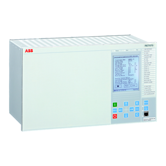
ABB RET670 Operator's Manual
Transformer protection
Hide thumbs
Also See for RET670:
- Applications manual (1016 pages) ,
- Commissioning manual (328 pages) ,
- Installation and commissioning manual (240 pages)
Table of Contents
Advertisement
Quick Links
Advertisement
Table of Contents

Related Manuals for ABB RET670


Summary of Contents for ABB RET670
- Page 1 ® Relion 670 series Transformer protection RET670 Operator's manual...
- Page 3 Document ID: 1MRK504114-UEN Issued: February 2015 Revision: E Product version: 1.2 © Copyright 2012 ABB. All rights reserved...
- Page 4 Copyright This document and parts thereof must not be reproduced or copied without written permission from ABB, and the contents thereof must not be imparted to a third party, nor used for any unauthorized purpose. The software and hardware described in this document is furnished under a license and may be used or disclosed only in accordance with the terms of such license.
- Page 5 In case any errors are detected, the reader is kindly requested to notify the manufacturer. Other than under explicit contractual commitments, in no event shall ABB be responsible or liable for any loss or damage resulting from the use of this manual or the application of the equipment.
- Page 6 (EMC Directive 2004/108/EC) and concerning electrical equipment for use within specified voltage limits (Low-voltage directive 2006/95/EC). This conformity is the result of tests conducted by ABB in accordance with the product standards EN 50263 and EN 60255-26 for the EMC directive, and with the product standards EN 60255-1 and EN 60255-27 for the low voltage directive.
-
Page 7: Table Of Contents
The Reset screen................24 LCD....................24 Small....................24 Medium..................24 LED....................25 Introduction..................25 Status indication LEDs..............25 Indication LEDs................25 Local HMI setup ................26 How to navigate................26 Read....................26 Change ..................26 Control..................27 Section 5 Understand the HMI tree..........29 Overview...................29 Menu-tree for RET670..............29 Section 6 Read measured values..........31 Overview...................31 Operator's manual... - Page 8 Table of contents View analog primary values..............32 Overview..................32 View analog secondary values............32 Overview..................32 View analog mean values..............33 Overview..................33 mA input module MIM............33 Signal matrix for mA inputs SMMI..........33 View monitoring values..............33 Service values CVMMXN............33 Current phasors CMMXU............33 Voltage phasors VMMXU/VNMMXU...........34 Current sequence component CMSQI........34 Voltage sequence component VMSQI........34 View metering values...............34...
- Page 9 Table of contents General settings................43 Power system................43 Overview................43 Identifiers................43 Primary values................43 Communication................43 Overview................43 Remote communication............43 SPA, LON and IEC 60870–5–103 settings......44 Station communication............45 Ethernet configuration............46 Analog and I/O modules..............47 Overview................47 Analog modules..............47 I/O modules................48 HMI....................48 Overview................48 LEDs..................48 Screen ...................48 Functions................49 Change lock ................49 Differential protection..............49 Overview................49...
- Page 10 Table of contents Overview................55 Pulse counter logic PCGGIO..........55 Function for energy calculation and demand handling ETPMMTR ................55 Setting group N.................56 Overview..................56 Differential protection..............56 Overview................56 Transformer differential protection, two winding T2WPDIF ................56 Transformer differential protection, three winding T3WPDIF ................56 Restricted earth fault protection REFPDIF ......56 High impedance differential protection HZPDIF ....57 Impedance protection..............57 Overview................57...
- Page 11 Table of contents Overview................60 Breaker failure protection CCRBRF ........61 Broken conductor check BRCPTOC ........61 Capacitor bank protection CBPGAPC........61 Directional over-power protection GOPPDOP ......61 Directional under-power protection GUPPDUP .....61 Instantaneous phase overcurrent protection PHPIOC ..61 Instantaneous residual overcurrent protection EFPIOC ..62 Negativ sequence time overcurrent protection for machines NS2PTOC..............62 Four step directional negative phase sequence...
- Page 12 Table of contents Current circuit supervision CCSRDIF ........66 Fuse failure supervision SDDRFUF........67 Control..................67 Overview................67 Synchrocheck and energizing check SESRSYN ....67 Tap changer control and supervision, 6 binary inputs TCMYLTC................67 Tap changer control and supervision, 32 binary inputs TCLYLTC ................67 Automatic voltage control for tapchanger, single control TR1ATCC ................67 Automatic voltage control for tapchanger, parallel control TR8ATCC ..............68...
- Page 13 Table of contents Differential protection ..............75 Impedance protection..............76 Current protection................76 Voltage protection ...............76 Frequency protection..............76 Multipurpose protection ..............76 Scheme communication .............76 Secondary system protection .............76 Control ..................77 Monitoring..................77 Logic....................77 Function status.................77 Overview..................77 Differential protection..............77 Transformer differential protection, two winding T2WPDIF ................77 Transformer differential protection, three winding T3WPDIF ................78 Restricted earth fault protection, low impedance...
- Page 14 Table of contents Mho Impedance supervision logic ZSMGAPC.......81 Pole slip protection PSPPPAM ..........81 Power swing detection ZMRPSB ..........81 Power swing logic ZMRPSL...........81 Current protection................82 Breaker failure protection CCRBRF........82 Broken conductor check BRCPTOC........82 Capacitor bank protection CBPGAPC........82 Directional over-power protection GOPPDOP.......82 Directional under-power protection GUPPDUP......82 Instantaneous phase overcurrent protection PHPIOC...82 Instantaneous residual overcurrent protection EFPIOC..83...
- Page 15 Table of contents Fuse failure supervision SDDRFUF........87 Control..................87 Apparatus control..............87 Commands................91 IEC61850 generic communication I/O functions DPGGIO.................92 Synchrocheck and energizing check SESRSYN ....92 Tap changer control and supervision TCMYLTC/ TCLYLTC................92 Automatic voltage control for tapchanger, single and parallel control TR1ATCC/TR8ATCC ........93 Monitoring..................93 Logical signal status report BINSTATREP......93 Disturbance report DRPRDRE..........93...
- Page 16 Table of contents Control screen messages............101 Section 13 Reset................103 Reset guide for IED................103 Reset counters................103 Circuit breaker SXCBR............103 Circuit switch SXSWI............103 Reset event counter CNTGGIO...........103 Reset pulse counter PCGGIO..........103 LDCM clear counters............103 Function for energy calculation and demand handling ETPMMTR................104 Tap changer control and supervision TCMYLTC, TCLYLTC................104 Reset disturbances and event list DRPRDRE......104...
-
Page 17: Section 1 Introduction
Section 1 1MRK504114-UEN E Introduction Section 1 Introduction About this chapter This chapter is an introduction to the operator’s manual, its purpose and usage. Introduction to the operator’s manual 1.1.1 About the complete set of manuals for an IED The user’s manual (UM) is a complete set of five different manuals: Engineeringmanual Installation and Commissioning manual... -
Page 18: About The Operator's Manual
Section 1 1MRK504114-UEN E Introduction manual should be used as a technical reference during the engineering phase, installation and commissioning phase, and during normal service. The Installation and Commissioning Manual (ICM) contains instructions on how to install and commission the protection IED. The manual can also be used as a reference during periodic testing. -
Page 19: Intended Audience
670 series SPA and signal list 1MRK 500 092-WEN IEC 61850 Data objects list for 670 series 1MRK 500 091-WEN Engineering manual 670 series 1MRK 511 240-UEN Communication set-up for Relion 670 series 1MRK 505 260-UEN More information can be found on www.abb.com/substationautomation. Operator's manual... -
Page 20: Revision Notes
Section 1 1MRK504114-UEN E Introduction 1.1.5 Revision notes Revision Description Minor corrections made Minor corrections made Maintenance updates, PR corrections Maintenance updates, PR corrections Operator's manual... -
Page 21: Section 2 Safety Information
Section 2 1MRK504114-UEN E Safety information Section 2 Safety information About this chapter This chapter lists warnings and cautions that must be followed when handling the IED. Warnings Do not touch circuitry during operation. Potentially lethal voltages and currents are present. Always connect the IED to protective earth, regardless of the operating conditions. -
Page 23: Section 3 Overview
Section 3 1MRK504114-UEN E Overview Section 3 Overview About this chapter This chapter presents a general overview of the Operator's manual. Operator overview The Local human-machine interface (LHMI) on the IED provides an ideal mechanism for the day to day operation and even advanced use of the IED. The keypad, LCD and LEDs on the front of the IED are what constitute the LHMI. - Page 24 Section 3 1MRK504114-UEN E Overview IEC10000336-1-en.vsd IED10000336 V1 EN Figure 1: Typical example of product identifier screen on local HMI IEDProdType is the Relion 670 series product type (REB, REC, RED, REG, REL, RET and so on) ProductDef specifies the version of the product, in the following order: major version.
- Page 25 Section 3 1MRK504114-UEN E Overview IEC10000337-1-en.vsd IEC10000337 V1 EN Figure 2: Typical example of IED product type and version properties in PCM600 FirmwareVer Specifies the version of the product firmware IEDMainFunType Specifies the main IED functionality, in accordance to IEC60870-5-103 numbering: •...
-
Page 27: Section 4 Understand The Ied Local Human-Machine Interface
Section 4 1MRK504114-UEN E Understand the IED local human-machine interface Section 4 Understand the IED local human- machine interface About this chapter This chapter describes the display, its keys (buttons) and LEDs that make up the local HMI on the IED. How the keys are used to navigate the HMI, how to interpret the graphic information on the LCD and, what the LEDs indicate is explained in the sections that follow. -
Page 28: Keypad
Section 4 1MRK504114-UEN E Understand the IED local human-machine interface IEC08000084 V1 EN Figure 4: 1/1 x 19” case with medium LCD Keypad The keypad is used to monitor and operate the IED. The keypad has the same look and feel in all IEDs. LCD screens and other details may differ but the way the keys function is identical. -
Page 29: Key Activated Screens
Section 4 1MRK504114-UEN E Understand the IED local human-machine interface Table 1: HMI keys on the front of the IED Function Press to close or energize a breaker or disconnector. IEC05000101 V1 EN Press to open a breaker or disconnector. IEC05000102 V1 EN Press to open two sub menus: Key operation and IED information. -
Page 30: The Reset Screen
Section 4 1MRK504114-UEN E Understand the IED local human-machine interface The I and O keys are used to open (OFF) and close (ON) breakers and disconnectors when using the Single Line Diagram (SLD) in direct control situations. 4.3.2 The Reset screen The reset screen is activated by the Reset key on the front panel of the IED or via the main menu. -
Page 31: Led
Section 4 1MRK504114-UEN E Understand the IED local human-machine interface 4.5.1 Introduction The LED module is a unidirectional means of communicating. This means that events may occur that activate a LED in order to draw the operators attention to something that has occurred and needs some sort of action. 4.5.2 Status indication LEDs The three LEDs above the LCD provide information as shown in the table below. -
Page 32: Local Hmi Setup
Section 4 1MRK504114-UEN E Understand the IED local human-machine interface • Position error • CB spring charge alarm • Oil temperature alarm • Thermal overload trip • Bucholtz trip The RJ45 port has a yellow LED indicating that communication has been established between the IED and a computer. -
Page 33: Control
Section 4 1MRK504114-UEN E Understand the IED local human-machine interface Navigate to the desired parameter or quantity using the arrow keys. Press the E key when the parameter to be changed is highlighted. Move between digits or letters using the left and right arrow keys. Use the up and down arrow keys to change the digit or letter concerned. -
Page 35: Section 5 Understand The Hmi Tree
• Test • Reset • Authorization • Language Each main menu item can have several other submenus. 5.1.1 Menu-tree for RET670 Main menu Sub menu Sub-sub menu Control Single line diagram Commands Measurements Analog primary values Analog secondary values Analog mean values... - Page 36 Section 5 1MRK504114-UEN E Understand the HMI tree Main menu Sub menu Sub-sub menu General settings Power system Communication Analog modules I/O modules Differential protection Current protection Voltage protection Control Monitoring Metering Setting group N Differential protection Impedance protection Current protection Voltage protection Frequency protection Multipurpose protection...
-
Page 37: Section 6 Read Measured Values
Section 6 1MRK504114-UEN E Read measured values Section 6 Read measured values About this chapter This chapter describes measurement categories and how to locate them using the HMI. Each measurement category has a section of its own that includes a general description of the type of quantity being measured and the path in the local HMI to the measurement. -
Page 38: View Analog Primary Values
Section 6 1MRK504114-UEN E Read measured values View analog primary values 6.2.1 Overview The analog primary values are analog quantities measured on the primary side of the TRM and reflect the actual current or voltage on the primary side of the VTs and CTs. -
Page 39: View Analog Mean Values
Section 6 1MRK504114-UEN E Read measured values View analog mean values 6.4.1 Overview Measurements from the Milliampere Input Module (MIM) are found in this part of the measurements menu. Data from either the hard wired mA module or Signal Matrix Tool mA modules are shown here. 6.4.1.1 mA input module MIM Main menu/Measurements/Analog mean values/mA modules/MIM:x... -
Page 40: Voltage Phasors Vmmxu/Vnmmxu
Section 6 1MRK504114-UEN E Read measured values 6.5.3 Voltage phasors VMMXU/VNMMXU Main menu/Measurements/Monitoring/VoltagePhasors(MMXU)/Phase - Phase/VMMXU:x Phase to phase voltages and phase angles are displayed here. Main menu/Measurement/Monitoring/VoltagePhasors(MMXU)/Phase - Earth/ VNMMXU:x Phase to earth voltages and phase angles are displayed here. 6.5.4 Current sequence component CMSQI Main menu/Measurements/Monitoring/CurrentSequenceComponents(MSQI)/... -
Page 41: Function For Energy Calculation And Demand Handling Etpmmtr
Section 6 1MRK504114-UEN E Read measured values 6.6.2 Function for energy calculation and demand handling ETPMMTR Main menu/Measurements/Metering/ThreePhEnergMeas(MMTR)/ ETPMMTR:x The output data generated from the energy measuring function includes active forward/reverse energy and reactive forward/reverse energy. Operator's manual... -
Page 43: Section 7 Event List
Section 7 1MRK504114-UEN E Event list Section 7 Event list About this chapter This chapter describes how to find and read the event list. View events 7.1.1 Overview Events displays recorded events such as trips and breaker opened or closed. Main menu/Events Displays a list of events in chronological order and where each event has a time stamp. -
Page 45: Section 8 Handle Disturbances
Section 8 1MRK504114-UEN E Handle disturbances Section 8 Handle disturbances About this chapter This chapter describes disturbance detection and handling. This includes resetting LED alarms, triggering disturbance reports and the viewing of several fault indicators. Identify a disturbance A disturbance record can be generated manually by using the Manual Trig functionality in the HMI menu. -
Page 46: View Trip Values
Section 8 1MRK504114-UEN E Handle disturbances Main menu/Disturbance records/Record xx/Event recording 8.2.4 View trip values In the Trip values section of a disturbance recording both the pre-fault and the fault values for current, voltage and phase angle can be viewed. The recording number and Trig time are also displayed. -
Page 47: Section 9 Read And Change Settings
Section 9 1MRK504114-UEN E Read and change settings Section 9 Read and change settings About this chapter This chapter describes how to find and change settings and parameters. The chapter is divided into two sections which match the way the two categories of settings are divided up in the HMI. -
Page 48: Timesynchbin
Section 9 1MRK504114-UEN E Read and change settings Here the parameters FineSyncSource, CourseSyncSrc and SyncMaster are switched on or off. Main menu/Settings/Time/Synchronization/TIMESYNCHGEN:x/ IEC61850-9-2 The synchronization parameters for IEC 61850-9-2LE process bus communication are set here. 9.1.2.3 TIMESYNCHBIN Main menu/Settings/Time/Synchronization/SYNCHBIN:x Binary input synchronization settings available here are the position of the of the module, the number of the binary input and the detection mode. -
Page 49: General Settings
Section 9 1MRK504114-UEN E Read and change settings General settings Parameters under General settings that are changed will cause the IED to restart. This occurs automatically and requires no manual intervention. The IED must be in setting group 1 before changing settings in General settings 9.2.1 Power system... -
Page 50: Spa, Lon And Iec 60870-5-103 Settings
Section 9 1MRK504114-UEN E Read and change settings Displays settings for Remote Binary Communication (CRB) and for Remote Multi Communication (CRM). The multi communication block can send both binary and analog data whereas the binary can only send binary data. Each instance of CRB has several settable parameters where the channel mode can be set on or off, terminal numbers can be entered, synchronization can be set to master or slave and opto power can be set high or low. -
Page 51: Station Communication
Section 9 1MRK504114-UEN E Read and change settings Rear optical SPA-IEC-DNP port Main menu/Settings/General settings/Communication/SLM configuration/ Rear optical SPA-IEC-DNP port In this submenu SPA or IEC is chosen and the necessary settings for the respective communication protocols are made. Main menu/Settings/General settings/Communication/SLM configuration/ Rear optical SPA-IEC-DNP port/Protocol selection SPA and IEC cannot run at the same time and in this submenu one of the options is chosen. -
Page 52: Ethernet Configuration
Section 9 1MRK504114-UEN E Read and change settings Main menu/Settings/General settings/Communication/Station communication/ MultiCommandSend/MULTICMDSND:x Includes available instances of Multicommand send settings allowing the user to adjust the maximum and minimum cycle time. Multicommand receive Main menu/Settings/General settings/Communication/Station communication/ MultiCommandReceive/MULTICMDRCV:x Includes available instances of Multicommand receive settings allowing the user to adjust the maximum and minimum cycle time, the pulse duration and mode of operation. -
Page 53: Analog And I/O Modules
Section 9 1MRK504114-UEN E Read and change settings Main menu/Settings/General settings/Communication/Ethernet configuration/ Gateway If a gateway is used to access the system the address to that gateway is entered here. 9.2.3 Analog and I/O modules 9.2.3.1 Overview Under Analog modules in the General settings menu there are settings for Analog inputs and I/O modules. -
Page 54: I/O Modules
Section 9 1MRK504114-UEN E Read and change settings Here is where the settings for the summation block are done. The summation type, Fourier filter reference frequency, minimum voltage for frequency measurement and the system voltage are some of the parameters that can be set here. Settings/General Settings/Analog modules/Reference channel service values The phase angle reference is set here. -
Page 55: Functions
Section 9 1MRK504114-UEN E Read and change settings Local HMI setting parameters such as Language, Contrast level and Default menu can be set here. 9.2.4.4 Functions Main menu/Settings/General Settings/HMI/Functions The settings here are used to determine the way information is presented in the HMI. 9.2.4.5 Change lock Main menu/Settings/General settings/HMI/Change lock... -
Page 56: Control
Section 9 1MRK504114-UEN E Read and change settings 9.2.6 Control 9.2.6.1 Apparatus control Overview Under Control in General settings, parameters for Apparatus control can be adjusted. These are the parameters for among others Bay control, Switch controller, Reservation input, Circuit breakers and Circuit switches. The parameters include delay times, dependencies, pulse times and characteristics. -
Page 57: Control Commands
Section 9 1MRK504114-UEN E Read and change settings Displays available instances of the local/remote function LocalRemote, LocRemControl that permit the user to set the control mode. Reservation input RESIN Main menu/Settings/General Settings/Control/Apparatus Control/ ReservationInput/RESINX:y Displays available instances of the Reservation input function RESIN with one settable parameter per function for future use. -
Page 58: Synchrocheck And Energizing Check Sesrsyn
Section 9 1MRK504114-UEN E Read and change settings Tap changer control and supervision TCMYLTC Main menu/Settings/General settings/Control/TransformerTapControl(YLTC, 84)/TCMYLTC:x Tap changer parameters such as tap positions for low and high voltage and type of code conversion are set here. Tap changer control and supervision TCLYLTC Main menu/Settings/General settings/Control/TransformerTapControl(YLTC, 84)/TCLYLTC:x Tap changer parameters such as tap positions for low and high voltage and type of... -
Page 59: Current Phasors Cmmxu
Section 9 1MRK504114-UEN E Read and change settings Main menu/Settings/General Settings/Monitoring/ServiceValues(MMXN)/ CVMMXN:x Displays available instances of CVMMXN. 9.2.7.3 Current phasors CMMXU Main menu/Settings/General Settings/Monitoring/CurrentPhasors(MMXU)/ CMMXU:x Displays available instances of the current phasor function CMMXU with output regarding current amplitude, current range, phase angle, zero sequence current magnitude and negative sequence current magnitude. -
Page 60: Disturbance Report Drprdre
Section 9 1MRK504114-UEN E Read and change settings voltage is 3U0, for positive sequence voltage is U1 and for negative sequence voltage is U2. There are sets of settings with some categories of parameter settings per set instance of VMSQI 9.2.7.7 Disturbance report DRPRDRE Main menu/Settings/General Settings/Monitoring/Disturbance Report/... -
Page 61: Logical Signal Status Report Binstatrep
Section 9 1MRK504114-UEN E Read and change settings 9.2.7.10 Logical signal status report BINSTATREP Main menu/Settings/General settings/Monitoring/BinarySignalStatusReport/ BINSTATREP:x The Binary signal status report BINSTATREP settings consist of some sets of settable parameters with one settable parameter per instance. 9.2.7.11 IEC 60870–5–103 Main menu/Settings/General settings/Monitoring/IEC 60870–5–103 The IEC 60870–5–103 part of the settings menu is divided into two separate submenus. -
Page 62: Setting Group N
Section 9 1MRK504114-UEN E Read and change settings Setting group N 9.3.1 Overview There are some default setting groups. Under general settings, parameters in these groups can be changed to suit the needs of an application. The default settings have been chosen according to established practice in the industry but will usually require a certain amount of adjustment to suit the requirements of individual applications. -
Page 63: High Impedance Differential Protection Hzpdif
Section 9 1MRK504114-UEN E Read and change settings Displays available instances of REFPDIF with some settings per instance. These are for the Current transformer ratios, operation, rated current Ibaseoperate angle of the zero sequence directional feature and Idmin which is a percentage of Ibase and is the current threshold in section one of the characteristic slope. -
Page 64: Distance Protection Zones, Quadrilateral Characteristics For Series Compensated Lines Zmcpdis, Zmcapdis
Section 9 1MRK504114-UEN E Read and change settings 9.3.3.4 Distance protection zones, quadrilateral characteristics for series compensated lines ZMCPDIS, ZMCAPDIS Main menu/Settings/Setting group N/Impedance protection/ DistanceZones(PDIS,21)/ZMCPDIS:1 Main menu/Settings/Setting group N/Impedance protection/ DistanceZones(PDIS,21)/ZMCAPDIS:x Displays available adjustable parameters. These include the ohm per phase for resistive and reactive reach as well as the ohm per loop for phase to phase, and phase to earth fault resistance. -
Page 65: Phase Selection, Quadrilateral Characteristic With Fixed Angle Fdpspdis
Section 9 1MRK504114-UEN E Read and change settings 9.3.3.8 Phase selection, quadrilateral characteristic with fixed angle FDPSPDIS Main menu/Settings/Setting group N/Impedance protection/ PhaseSelection(PDIS,21)/FDPSPDIS:x Displays available settings including minimum operating current for both phase- phase and phase-earth fault loops. 9.3.3.9 Phase selection, quadrilateral characteristic with settable angle FRPSPDIS Settings/Setting Group N/Impedance protection/PhaseSelections(PDIS,21)/ FRPSPDIS:x... -
Page 66: Additional Distance Protection Directional Function For Earth Faults Zdardir
Section 9 1MRK504114-UEN E Read and change settings 9.3.3.14 Additional distance protection directional function for earth faults ZDARDIR Main menu/Settings/Setting Group N/Impedance protection/ MhoDirectionEF(RDIR)/ZDARDIR:x Includes settings for minimum operate currents, polarizing mode and angles for directional measurement. 9.3.3.15 Mho impedance supervision logic ZSMGAPC Main menu/Settings/Setting Group N/Impedance protection/ MhoSupervisionLogic(GAPC)/ZSMGAPC:x Parameters for current and voltage change levels are set here. -
Page 67: Breaker Failure Protection Ccrbrf
Section 9 1MRK504114-UEN E Read and change settings many others. The thermal overload functions have temperature threshold settings as well as many others necessary for adapting the function to a particular application. 9.3.4.2 Breaker failure protection CCRBRF Main menu/Settings/Setting Group N/Current protection/ BreakerFailure(RBRF,50BF)/CCRBRF:x Displays some instances of CCRBRF with several settings per instance. -
Page 68: Instantaneous Residual Overcurrent Protection Efpioc
Section 9 1MRK504114-UEN E Read and change settings 9.3.4.8 Instantaneous residual overcurrent protection EFPIOC Main menu/Settings/Setting Group N/Current protection/ InstResidualOverCurrent(PIOC,50N)/EFPIOC:x Displays some instances of EFPIOC with settable parameters per instance. The settable parameters are operation (On or Off), base setting for current magnitude, the threshold current as a percentage of IBase, and the multiplier for the current threshold level. -
Page 69: Sensitive Directional Residual Over Current And Power Protection Sdepsde
Section 9 1MRK504114-UEN E Read and change settings Displays some instances of EF4PTOC with a large number of settings per instance. Typical settings are those for harmonic restraint, minimum fundamental frequency current level, base settings for current and voltage and several others. 9.3.4.14 Sensitive directional residual over current and power protection SDEPSDE... -
Page 70: Overexcitation Protection Oexpvph
Section 9 1MRK504114-UEN E Read and change settings 9.3.5.3 Overexcitation protection OEXPVPH Main menu/Settings/Setting Group N/Voltage protection/ Overexcitation(PVPH,24)/OEXPVPH:x Displays settable parameters for operation, rated current and voltage, time delays for user designed curves and several other related settings. 9.3.5.4 Two step overvoltage protection OV2PTOV Main menu/Settings/Setting Group N/Voltage protection/ OverVoltage2Step(PTOV,59)/OV2PTOV:x Displays several settable parameters including settings for IDMT curves and other... -
Page 71: Overfrequency Protection Saptof
Section 9 1MRK504114-UEN E Read and change settings 9.3.6.2 Overfrequency protection SAPTOF Main menu/Settings/Setting Group/Frequency protection/ OverFrequency(PTOF,81)/SAPTOF:x Displays available instances of SAPTOF with a number of settings per instance. The settings are operation, start frequency, base voltage setting, internal blocking level, operate time delay and reset time delay. -
Page 72: Scheme Communication
Section 9 1MRK504114-UEN E Read and change settings 9.3.8 Scheme communication 9.3.8.1 Overview Under Scheme communication there are settings for Zone scheme communication, Zone current reversal, Local acceleration logic, EF Scheme communication and EF Current reversal weak end infeed. In each category the function can be switched On or Off and time delays, ratings and parameters can be set. -
Page 73: Fuse Failure Supervision Sddrfuf
Section 9 1MRK504114-UEN E Read and change settings 9.3.9.3 Fuse failure supervision SDDRFUF Main menu/Settings/Setting Group N/Secondary system supervision/ FuseFailure(RFUF)/SDDRFUF:x Displays available instances of SDDRFUF with several settings per instance. There are parameters for operation, various thresholds and base values. 9.3.10 Control 9.3.10.1... -
Page 74: Automatic Voltage Control For Tapchanger, Parallel Control Tr8Atcc
Section 9 1MRK504114-UEN E Read and change settings Parameters for current and voltage levels, deadbands, timers and alarm levels are found here. 9.3.10.6 Automatic voltage control for tapchanger, parallel control TR8ATCC Main menu/Settings/Setting Group N/Control/ TransformerVoltageControl(ATCC,90)/TR8ATCC:x Parameters for current and voltage levels, deadbands, timers and alarm levels are found here. -
Page 75: Logicgate
Section 9 1MRK504114-UEN E Read and change settings 9.3.12.4 LogicGate Main menu/Settings/Setting group N/Logic/LogicGate/GATE:x Displays parameter settings for Operation (On or Off). 9.3.12.5 LogicRSMemory Main menu/Settings/Setting group N/Logic/LogicRSMemory/RSMEMORY:x Displays setting parameters for operating mode of memory function. 9.3.12.6 LogicSRMemory Main menu/Settings/Setting group N/Logic/LogicSRMemory/SRMEMORY:x Displays setting parameters for operating mode of memory function. -
Page 77: Section 10 Diagnose Ied Status
Section 10 1MRK504114-UEN E Diagnose IED status Section 10 Diagnose IED status About this chapter This chapter describes where in the HMI tree to find the cause of an internal IED failure and information about the IED as such. 10.1 Read internal events Main menu/Diagnostics/Internal events Internal events in the diagnostics menu of the HMI tree shows a time stamped list... - Page 78 Section 10 1MRK504114-UEN E Diagnose IED status Main menu/ Diagnostics/Communication/Front port Displays various communication status signals for front port communication. Main menu/ Diagnostics/Communication/Rear OEM - port AB Displays various communication status signals for rear AB port communication. Main menu/ Diagnostics/Communication/Rear OEM - port CD Displays various communication status signals for rear CD port communication.
-
Page 79: Section 11 Test The Ied
Section 11 1MRK504114-UEN E Test the IED Section 11 Test the IED About this chapter This chapter describes the tests that can be performed in the test section of the HMI. 11.1 Overview The test part of the tree view in the HMI has a number of submenus for test and viewing activities. -
Page 80: Ied Test Mode
Section 11 1MRK504114-UEN E Test the IED 10. Control displays the Synchrocheck, and Apparatus control functions. The Synchrocheck functions include a number of function related measurements such as calculated differences. Apparatus control includes up to 19 functions each with their own set of measurement data regarding interlocking, breaker and isolator conditions. -
Page 81: Signal Matrix For Binary Input Smbi
Section 11 1MRK504114-UEN E Test the IED Displays available binary input modules with several binary values per module. 11.3.1.2 Signal matrix for binary input SMBI Main menu/Test/Binary Input Values/SMT binary inputs/Instance:x Displays available instances of SMT binary inputs with several inputs per instance. 11.4 View binary output values 11.4.1... -
Page 82: Impedance Protection
Section 11 1MRK504114-UEN E Test the IED 11.5.3 Impedance protection Main menu/Test/Function test mode/Impedance protection Test of switch onto fault logic, distance protection zones one to five, local acceleration logic, power swing detection and phase selection with load encroachment. 11.5.4 Current protection Main menu/Test/Function test modes/Current protection Test of breaker failure protection, phase overcurrent protection,residual overcurrent... -
Page 83: Control
Section 11 1MRK504114-UEN E Test the IED Test of current circuit supervision and fuse failure supervision. 11.5.10 Control Main menu/Test/Function test modes/Control Test of synchrocheck and energizing check function. 11.5.11 Monitoring Main menu/Test/Function test modes/Monitoring Test of monitoring functions such as event counter and disturbance report. 11.5.12 Logic Main menu/Test/Function test modes/Logic... -
Page 84: Transformer Differential Protection, Three Winding T3Wpdif
Section 11 1MRK504114-UEN E Test the IED 11.6.2.2 Transformer differential protection, three winding T3WPDIF Main menu/Test/Function status/Differential protection/ TransDifferential3Wind(PDIF,87T)/T3WPDIF:x Displays up to two instances of T3WPDIF with several measured values each. The data output here is identical to that shown in section "Transformer differential protection, two winding T2WPDIF"... -
Page 85: Distance Protection Zone, Quadrilateral Characteristic Zmcpdis, Zmcapdis
Section 11 1MRK504114-UEN E Test the IED Displays instances of ZMQPDIS for zone 1. The output quantities shown here indicate trip and start signal status. Main menu/Test/Function status/Impedance Protection/DistanceZones(PDIS, 21)/ZMQAPDIS:x Displays available instance of ZMQAPDIS for zones 2-5. The output quantities shown here indicate trip and start signal status. -
Page 86: Faulty Phase Identification With Load Enchroachment Fmpspdis
Section 11 1MRK504114-UEN E Test the IED 11.6.3.6 Faulty phase identification with load enchroachment FMPSPDIS Main menu/Test/Function status/Impedance protection/PhaseSelection(PDIS, 21)/FMPSPDIS:x Includes current and voltage level settings. 11.6.3.7 Phase selection with load encroachment FDPSPDIS Main menu/Test/Function status/Impedance Protection/PhaseSelection(PDIS, 21)/FDPSPDIS:x Displays one instance of FDPSPDIS with a number of measurements. These measurements show faults detected per phase as well as start conditions. -
Page 87: Directional Impedance Quadrilateral, Including Series Compensation Zdsrdir
Section 11 1MRK504114-UEN E Test the IED 11.6.3.12 Directional impedance quadrilateral, including series compensation ZDSRDIR Main menu/Test/Function status/Impedance Protection/ DirectionalImpedanceSC(RDIR,21D)/ZDSRDIR:x Displays instances of ZDSRDIR . 11.6.3.13 Additional distance protection directional function for earth faults ZDARDIR Main menu/Test/Function status/Impedance protection/ MhoDirectionEF(RDIR)/ZDARDIR:x Displays the output data of ZDARDIR function. -
Page 88: Current Protection
Section 11 1MRK504114-UEN E Test the IED 11.6.4 Current protection Viewable data under Current protection consists mainly of trip status data under the various categories of current protection which include overcurrent protection, thermal overload, pole discordance and variations of these. 11.6.4.1 Breaker failure protection CCRBRF Main menu/Test/Function status/Current protection/BreakerFailure(RBRF,... -
Page 89: Instantaneous Residual Overcurrent Protection Efpioc
Section 11 1MRK504114-UEN E Test the IED Displays available instances of PHPIOC with a number of measurements per instance showing the trip status in general and per phase. 11.6.4.7 Instantaneous residual overcurrent protection EFPIOC Main menu/Test/Function status/Current protection/ InstResidualOverCurrent(PIOC,50N)/EFPIOC:x Displays available instances of EFPIOC with one trip value per instance. 11.6.4.8 Negative sequence time overcurrent protection for machines NS2PTOC... -
Page 90: Sensitive Directional Residual Over Current And Power Protection Sdepsde
Section 11 1MRK504114-UEN E Test the IED Displays available instances of EF4PTOC with a number of measurements per instance. The measurements indicate trip and start signal status as well as the 2nd harmonic block signal status. 11.6.4.13 Sensitive directional residual over current and power protection SDEPSDE Main menu/Test/Function status/Current protection/ SensDirResOvCurr(PSDE,67N)/SDEPSDE:x... -
Page 91: Two Step Overvoltage Protection Ov2Ptov
Section 11 1MRK504114-UEN E Test the IED Displays available instances of OEXPVPH with a number of measurements per instance. These measurements indicate whether values are out of the measuring range (ERROR) and if the overexcitation function has caused a trip (TRIP). The thermal status as a percentage of the trip level and the calculated time to trip are among the other outputs available here. -
Page 92: Rate-Of-Change Frequency Protection Sapfrc
Section 11 1MRK504114-UEN E Test the IED Displays available instances of SAPTOF with some measurements per instance consisting of trip and start signal status. The start duration as percentage of the total trip time and a blocking indication as a result of low voltage. 11.6.6.2 Rate-of-change frequency protection SAPFRC Main menu/Test/Function status/Frequency protection/... -
Page 93: Scheme Communication Logic For Residual Overcurrent Protection Ecpsch
Section 11 1MRK504114-UEN E Test the IED Displays one instance of ECRWPSCH with four measurements per instance. 11.6.8.2 Scheme communication logic for residual overcurrent protection ECPSCH Main menu/Test/Function status/Scheme communication/ EFSchemeCommunication(PSCH,85)/ECPSCH:x Displays available instances of ECPSCH with some measurements indicating carrier and trip status. - Page 94 Section 11 1MRK504114-UEN E Test the IED Displays available instances of the function with an open and a close parameter for each disconnection device. The enable open (EN_OPEN) parameter will have the output value one if an open operation is allowed and a zero output if an open operation is not allowed.
- Page 95 Section 11 1MRK504114-UEN E Test the IED Displays available measurements per breaker arrangement (instances of BH_LINE_AIL). The measurements show the states of the various disconnectors, breakers and earthing switches. Interlock one and a half circuit breaker line B BH_LINE_B Main menu/Test/Function status/Control/Apparatus control/ Interl11½CBLineB/BH_LINE_B:x Displays available measurements per arrangement (instance of BH_LINE_B) showing conditions for breakers, disconnectors and earthing switches in the...
- Page 96 Section 11 1MRK504114-UEN E Test the IED Interlock, transformer bay AB_TRAFO Main menu/Test/Function status/Control/Apparatus control/ InterlTransformerBay/AB_TRAFO:x Shows available instances of the function with several measurements per instance. The measurements indicate which breakers and disconnectors are permitted to open and/or close, the status of the disconnect devices and switch status validity. For example, the measurement named VPQB2TR indicates with output value 1 that the switch status of disconnector QB2 is valid.
-
Page 97: Commands
Section 11 1MRK504114-UEN E Test the IED BayRes blocks the output values are all boolean and indicate the status of processes and devices. Reservation input RESIN Main menu/Test/Function status/Control/Apparatus control/ReservationInput/ RESINx:y Displays available instances of the function RESIN with six measurements per instance. -
Page 98: Iec61850 Generic Communication I/O Functions Dpggio
Section 11 1MRK504114-UEN E Test the IED There are OUT signals under the Single command menu. Selector switch SLGGIO Main menu/Test/Function status/Control/Commands/SelectorSwitch(GGIO)/ SLGGIO:x An application dependent number of switches can be displayed here. The position of each switch is indicated here. There are up to a number of possible switch positions. -
Page 99: Automatic Voltage Control For Tapchanger, Single And Parallel Control Tr1Atcc/Tr8Atcc
Section 11 1MRK504114-UEN E Test the IED 11.6.10.6 Automatic voltage control for tapchanger, single and parallel control TR1ATCC/TR8ATCC Settings/Test/Function status/Control/TransformerVoltageControl(ATCC,90)/ TR1ATCC:x Settings/Test/Function status/Control/TransformerVoltageControl(ATCC,90)/ TR8ATCC:x Displays parameters for current and voltage levels, deadbands, timers and alarm levels. 11.6.11 Monitoring Monitoring includes large amounts of viewable data including Disturbance report data, Service values, Current phasors, Voltage phasors, Milliampere signal level supervision, Binary signal status report, Events, MVGGIO, MVExpander and LEDs. -
Page 100: Generic Measured Value Mvggio
Section 11 1MRK504114-UEN E Test the IED 11.6.11.4 Generic measured value MVGGIO Main menu/Test/Function status/Monitoring/GenericMeasuredValue(GGIO)/ MVGGIO:x Displays the analog output from the MVGGIO block. The value shown here depends on the settings and the logical configuration of the preprocessing blocks. The measurement displayed may be current, voltage, frequency, phase angle etc. -
Page 101: Logic
Section 11 1MRK504114-UEN E Test the IED 11.6.12 Logic Under the Logic function folder there is viewable data for trip logic (showing number of poles that have tripped and trip signal information), event counter values, Logic gate outputs, Logic SR memory output states and Logic timer set output states are also shown here. -
Page 102: Logic Sr/Rs Memory
Section 11 1MRK504114-UEN E Test the IED 11.6.12.6 Logic SR/RS memory Main memory/Test/Function status/Logic/LogicSRMemory/SRMEMORY:x Main memory/Test/Function status/Logic/LogicRSMemory/RSMEMORY:x Displays available instances of the function SRMEMORY/RSMEMORY. The output data presented in the HMI is boolean and indicates whether or not a signal is present. -
Page 103: Setting Groups
Section 11 1MRK504114-UEN E Test the IED MultiCommand receive Main menu/Test/Function status/Communication/Station communication/ MultipleCommandReceive/MULTICMDRCV:x The MultiCommand Receive indications displayed here show available sets of output data. Each set of output data has a number of signals. Other information displayed here shows whether there has been a change in data and whether data is valid. -
Page 104: Line Differential Test
Section 11 1MRK504114-UEN E Test the IED The Test LEDs menu enables the operator to activate LEDs manually. LEDs that do not light up are defective. Defective LEDs are also logged in Disturbance records under Monitoring. 11.8 Line differential test Main menu/Test/Line differential test/LineDiffLogic Settings used during test of line differential protection including test mode setting. -
Page 105: Section 12 Control And Supervise The Bay
Section 12 1MRK504114-UEN E Control and supervise the bay Section 12 Control and supervise the bay About this chapter This chapter describes the various control and supervision functions available in the HMI. In particular, how the single line diagram available on the display can be used for this purpose. - Page 106 Section 12 1MRK504114-UEN E Control and supervise the bay Main menu/Control/Single Line Diagram This is the path to the single line diagram from the main menu. The symbols used in the Single Line Diagram (SLD) are described in the table below Symbol Description Autotransformer...
-
Page 107: Control Screen Messages
Section 12 1MRK504114-UEN E Control and supervise the bay Symbol Description Surge arrestor xx05000243.vsd IEC05000243 V1 EN Trafo 2 windings xx05000244.vsd IEC05000244 V1 EN Trafo 3 windings xx05000245.vsd IEC05000245 V1 EN Truck xx05000248.vsd IEC05000248 V1 EN VT 2 windings xx05000247.vsd IEC05000247 V1 EN 12.1.3 Control screen messages... -
Page 109: Section 13 Reset
Section 13 1MRK504114-UEN E Reset Section 13 Reset About this chapter This chapter describes how to reset the IED and when this is necessary. 13.1 Reset guide for IED 13.1.1 Reset counters 13.1.1.1 Circuit breaker SXCBR The circuit breaker counter is reset under Reset counter in the HMI tree. Main menu/Reset/Reset counters/CircuitBreaker(XCBR)/SXCBR:x In the dialog box that appears, choose YES to reset. -
Page 110: Function For Energy Calculation And Demand Handling Etpmmtr
Section 13 1MRK504114-UEN E Reset Activating Reset of LDCM counters sets the counter concerned to zero. A reset can be performed by affirmation in the dialog box. This is done by pressing the E key when YES is highlighted. 13.1.1.6 Function for energy calculation and demand handling ETPMMTR Main menuReset/Reset counters/ThreePhEnergMeas(MMTR)/ETPMMTR:x Resetting accumulated energy values and the maximum demand values. -
Page 111: Reset Lockout Smpptrc
Section 13 1MRK504114-UEN E Reset In the dialog box that appears, choose YES to reset. 13.1.4 Reset lockout SMPPTRC Objects that are considered at risk after a trip may be prevented from reconnecting by a lockout condition. The reset lockout facility is used to undo a lockout condition caused by a such a trip. -
Page 113: Section 14 Authorization
Section 14 1MRK504114-UEN E Authorization Section 14 Authorization About this chapter This chapter describes password procedures and levels of access in the system. 14.1 Overview To safeguard the interests of our customers, both the IED and the tools that are accessing the IED are protected, by means of authorization handling. - Page 114 Section 14 1MRK504114-UEN E Authorization Table 2: Pre-defined user types Access rights System Protection Design User Guest Super User SPA Guest Operator Engineer Engineer Administrator Basic setting possibilities (change setting group, control settings, limit supervision) Advanced setting possibilities (for example protection settings) Basic control possibilities (process control, no bypass) Advanced control possibilities...
-
Page 115: Logon Or Logoff
Section 14 1MRK504114-UEN E Authorization At least one user must be included in the UserAdministrator group to be able to write users, created in PCM600, to IED. 14.3 LogOn or logOff The Authorization menu allows the user to logOn and, logOff. The HMI path is as follows: Main menu/Authorization 14.4... -
Page 116: Internet Protocol Ports Security Guideline
Section 14 1MRK504114-UEN E Authorization 14.5 Internet Protocol ports security guideline The Internet Protocol ports security guide line can not suggest concrete products for a secure system setup. This must be decided along the specific project, requirements and existing infrastructure. The required external equipment can be separated devices or devices that combine firewall, router and secure VPN functionality. - Page 117 Section 14 1MRK504114-UEN E Authorization Ethernet communication is used. Only one type is possible for a specific configuration. • The PCM600 port for SPA (port 7001) is used for configuration and parameter setting using the PCM600 tool and a proprietary protocol SPA and is fixed and can not be changed.
-
Page 119: Section 15 Glossary
Section 15 1MRK504114-UEN E Glossary Section 15 Glossary About this chapter This chapter contains a glossary with terms, acronyms and abbreviations used in ABB technical documentation. Alternating current Application configuration tool within PCM600 A/D converter Analog-to-digital converter ADBS Amplitude deadband supervision... - Page 120 Section 15 1MRK504114-UEN E Glossary Combined backplane module CCITT Consultative Committee for International Telegraph and Telephony. A United Nations-sponsored standards body within the International Telecommunications Union. CAN carrier module CCVT Capacitive Coupled Voltage Transformer Class C Protection Current Transformer class as per IEEE/ ANSI CMPPS Combined megapulses per second Communication Management tool in PCM600...
- Page 121 Section 15 1MRK504114-UEN E Glossary Distributed Network Protocol as per IEEE Std 1815-2012 Disturbance recorder DRAM Dynamic random access memory Disturbance report handler Digital signal processor Direct transfer trip scheme EHV network Extra high voltage network Electronic Industries Association Electromagnetic compatibility (Electromotive force) Electromagnetic interference EnFP...
- Page 122 Section 15 1MRK504114-UEN E Glossary Human-machine interface HSAR High speed autoreclosing High-voltage HVDC High-voltage direct current IDBS Integrating deadband supervision International Electrical Committee IEC 60044-6 IEC Standard, Instrument transformers – Part 6: Requirements for protective current transformers for transient performance IEC 60870-5-103 Communication standard for protective equipment.
- Page 123 Section 15 1MRK504114-UEN E Glossary IP 20 Ingression protection, according to IEC standard, level 20 IP 40 Ingression protection, according to IEC standard, level 40 IP 54 Ingression protection, according to IEC standard, level 54 Internal failure signal IRIG-B: InterRange Instrumentation Group Time code format B, standard 200 International Telecommunications Union Local area network...
- Page 124 Section 15 1MRK504114-UEN E Glossary PCM600 Protection and control IED manager PC-MIP Mezzanine card standard PCI Mezzanine card Permissive overreach POTT Permissive overreach transfer trip Process bus Bus or LAN used at the process level, that is, in near proximity to the measured and/or controlled components Power supply module Parameter setting tool within PCM600 PT ratio...
- Page 125 Section 15 1MRK504114-UEN E Glossary SNTP Simple network time protocol – is used to synchronize computer clocks on local area networks. This reduces the requirement to have accurate hardware clocks in every embedded system in a network. Each embedded node can instead synchronize with a remote clock, providing the required accuracy.
- Page 126 Section 15 1MRK504114-UEN E Glossary UTC is derived from International Atomic Time (TAI) by the addition of a whole number of "leap seconds" to synchronize it with Universal Time 1 (UT1), thus allowing for the eccentricity of the Earth's orbit, the rotational axis tilt (23.5 degrees), but still showing the Earth's irregular rotation, on which UT1 is based.
- Page 128 Contact us ABB AB Substation Automation Products SE-721 59 Västerås, Sweden Phone +46 (0) 21 32 50 00 +46 (0) 21 14 69 18 www.abb.com/substationautomation...
Need help?
Do you have a question about the RET670 and is the answer not in the manual?
Questions and answers