
Related Manuals for Flashforge Inventor


Summary of Contents for Flashforge Inventor
- Page 1 FlashForge Corporation FlashForge Inventor 3D Printer User Guide Inventor User Guide | www.FlashForge.com 400-699-1063...
-
Page 2: Table Of Contents
Content..........................2 Introduction........................4 Notice..........................5 Chapter 1: 3D Printing Technology................8 1.1 Process....................... 8 Chapter 2 . About Inventor....................10 2.1 About Your Inventor..................10 2.1.1 Main view:....................10 Chapter 3. Unpacking....................14 Chapter 4 . Hardware Assembly................... 17 4.1 Mounting the Extruder Set................17 4.2 Installing Filament................... - Page 3 FlashForge Inventor. Even if you are familiar with earlier FlashForge machines or 3D printing technology, we still recommend that you read through this guide, as there is lots of important information about the Inventor for you to get a better 3D experience.
-
Page 4: Introduction
·The User Guide is written based on Windows 7 OS. ·The version of the FlashPrint is latest. The FlashForge Inventor 3D Printer User Guide contains the information needed for you to set up and use this device. This User Guide including the following parts: Preface, Introduction and After-sale service. -
Page 5: Notice
① Always use the Inventor with a properly grounded outlet. Do not modify Inventor plug. ② Do not use Inventor in damp or wet locations. Do not expose Inventor to burning sun. ③In case of device damage, please use the power supply provided by FlashForge. - Page 6 The device must be placed in a dry and ventilated environment. The distances of the left, right and back side space should be at least 20cm, and the distance of the front side space should be at least 35cm. Inventor User Guide | www.FlashForge.com 400-699- 1063...
- Page 7 · Filament Requirements Do not abuse the filament. Please make sure you use the FlashForge filament or the filament from the brands accepted by FlashForge. · Filament Storage All polymers degrade with time. Do not unpack filament until necessary. Filament should be stored at clean and in dry conditions.
-
Page 8: Chapter 1: 3D Printing Technology
Fused Filament Fabrication (FFF) is the most common method of 3D printing. It is also the method that the Inventor uses. It works by melting plastic material called filament onto a print surface in high temperature. The filament solidifies after it cools down, which happens instantaneously after it is extruded from the nozzle. - Page 9 Inventor via USB cable, SD card or Wi-Fi. 1.1.3 Build the 3D Model Once the output file has been transferred to your Inventor, it will start to turn the 3D model into a physical object by laying down layers of filament.
-
Page 10: Chapter 2 . About Inventor
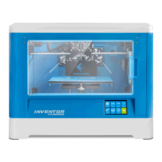
Chapter 2 . About Inventor 2.1 About Your Inventor 2.1.1 Main view: 1. Camera Whole Machine 2. Extruder 3. Timing belt 4. Panel 5. Build plate 6. Filament 7. Power input 8. Power switch 9. Touch screen 10. Reset button 11. - Page 11 Power Cable USB Cable Panel*2 Filament*2 Turbofan Baffle Toolbox Build Tape Quick Start Guide Tweezers SD Card Leveling Card Screwdriver Scraper Screw Box Carving Knife Stamping Wrench Unclogging Pin Tool Allen Wrench Grease Inventor User Guide | www.FlashForge.com 400-699- 1063...
- Page 12 2.1.3 Terms The surface on which the Inventor builds an object. Build Plate The blue tape that covers Inventor’s build plate so that Build Tape the object can stick to the build plate well. The three dimensional amount of space that an object Build Volume will use once it is completed.
- Page 13 Filament Diameter 1.75mm(±0.07) Filament Types ABS/PLA/Conductive PLA/Flexible Filament Software FlashPrint Input: 3MF/STL/OBJ/FPP/BMP/PNG/JPG/JPEG; Support Formats Output: GX/G Win xp/Vista/7/8/10、Mac OS、Linux 485*344*382(402)mm Device Size Net Weight 10.7Kg AC Input 100-240V~/4.5A-2.5A Connectivity USB cable, SD card, WiFi Inventor User Guide | www.FlashForge.com 400-699- 1063...
-
Page 14: Chapter 3. Unpacking
Set this aside for now. The Inventor unit and a will then be exposed. 3. ( ) Lift the Inventor by its side openings and place it on a flat surface. Then you will see the Toolbox USB cable in the shipping box. - Page 15 4.(3-4)The Inventor will have an accessory box on top of it, which will contain the extruder set. Remove the box and the foam pad from the Inventor, and gently lay the extruder set on the Inventor build plate. Extruder Accessory Kit...
- Page 16 (3-6)Take out the PLA filament and ABS filament carefully which is under the build plate. (3-7)You’ve finished unpacking your Inventor. Next we will move on to the hardware assembly. Inventor User Guide | www.FlashForge.com 400-699- 1063...
-
Page 17: Chapter 4 . Hardware Assembly
The Inventor comes pre-assembled and is almost ready-to-print (ARP). All you need to do is to set the appropriate voltage, mount the extruder set, and install the filament. It will only take 5 to 10 minutes to set up the Inventor and prepare for your first 3D print! 4.1 Mounting the Extruder Set... - Page 18 Insert the bump on the turbofan seat to the turbofan sub-assembly. Screw the two bolts in. Take a M3 x 6 bolt from the extruder’s accessory kit and complete installation. Inventor User Guide | www.FlashForge.com 400-699- 1063...
-
Page 19: Installing Filament
(4-5) Feed the filament through the filament guide tube. Attach the guide tube onto the two filament guide tube brackets. (4-6) Stick the build sheet to the build plate after installing filament, as picture shows. Inventor User Guide | www.FlashForge.com 400-699- 1063... -
Page 20: Plugging In Power Cable&Usb Cable
4.3 Plugging in Power Cable&USB Cable (4-7) Locate the power cable, and plug it into the Inventor. Optional: Locate the USB cable and plug one end into the Inventor and the other into your computer. The Inventor supports USB connectivity. 4.4 Loading and Unloading Filament Filament must pass through the extruder and into the heating block in order to be melted. - Page 21 (4-11)Wait for the extruder to heat up to the operating temperature. The extruder will alert you once it is at the operating temperature. Load the filament by inserting it into the extruder at an upright angle. Inventor User Guide | www.FlashForge.com 400-699- 1063...
-
Page 22: Unloading Filament
Refer to the troubleshooting section if the [Done] filament is extruding abnormally. Then tap to finish loading. Unloading filament: 4-13 (4-13) Remove the lid of the Inventor 4-14 (4-14) From the main menu, tap the right icon labeled [Tool]. Inventor User Guide | www.FlashForge.com 400-699- 1063... - Page 23 (4-16)Wait for the extruder to heat up to the operating temperature. The extruder will alert you once it is at the operating temperature.(4-17) Unload the filament by gently guiding it out of the extruder. Then tap [Done] to finish unloading. Inventor User Guide | www.FlashForge.com 400-699- 1063...
-
Page 24: Chapter 5: Build Plate Leveling
The Inventor utilizes a three-point leveling system for its build plate. At the bottom of the build plate, there is one spring-loaded knob in the front and two in the back. - Page 25 Slide the paper back and forth again, and adjust the screw to create the same amount of friction as the previous step. Inventor User Guide | www.FlashForge.com 400-699- 1063...
- Page 26 Slowly adjust all the screws by the same amount if there is no friction or too much friction. [Finish] once you have finished this. (5-7)Tap Inventor User Guide | www.FlashForge.com 400-699- 1063...
-
Page 27: Chapter 6: About Software
1. Decompress the zipped file or start the installation program, and then install the software according to the direction. 2. Click the software icon to start the software with the start menu shortcut.(See 6-1) Inventor User Guide | www.FlashForge.com 400-699- 1063... -
Page 28: Exploring Flashprint
Notice! After starting FlashPrint, you need to select the target machine type first. When you start FlashPrint, a dialog box will pop up. Just need to select FlashForge Inventor in the machine type list and click [OK]. You can also change the machine type via clicking [Print]--[Machine type]. - Page 29 Turn and rotate your model Scale the size of your object Cut the model into several parts Print it directly with your Inventor or export to your SD card. Select right or left extruder you want to print with. 6.2.3 Loading...
- Page 30 Bottom thickness: To set up bottom thickness for tube, canister, lamp and seal. Top diameter: To set up the top diameter for tube, canister, lamp and seal. Bottom diameter: To set up the bottom diameter for tube, canister, lamp and seal. Inventor User Guide | www.FlashForge.com 400-699- 1063...
- Page 31 Plane 6-5 Tube 6-6 Canister 6-7 Inventor User Guide | www.FlashForge.com 400-699- 1063...
- Page 32 Change model views by moving, rotating, scaling. ● Drag [View] Click the icon and then you can move the object by the following three methods: Method 1: Hold down the left mouse button and drag. Inventor User Guide | www.FlashForge.com 400-699- 1063...
- Page 33 [Reset]. ④ Show Model Outline Click [View]--[Show Model Outline], it will highlight the yellow border of the object ⑤ Show Steep Overhang Inventor User Guide | www.FlashForge.com 400-699- 1063...
- Page 34 X/Y/Z axis. Method 2: Click the [Rotate] icon on the left, and then enter into rotating [Reset] angel values in X/Y/Z axes positioning. Click to reset rotating angel values. Inventor User Guide | www.FlashForge.com 400-699- 1063...
- Page 35 6.2.8 Left-click on the model to select it and double-click on the [Cut] icon to set the cut plane. The direction and position are available for setting. ①Draw with Mouse Inventor User Guide | www.FlashForge.com 400-699- 1063...
- Page 36 ②X Plane ③Y Plane ④Z Plane 6.2.9 Extruder (6-10) Choose L/R extruder to print, pitch on the model, click on two times, now you can set extruder . Inventor User Guide | www.FlashForge.com 400-699- 1063...
- Page 37 “treelike” and “linear”, when choose “treelike”, click [OK], then the support generated will be treelike structure; when choose “linear”, click [OK], then the support generated will be linear structure; if the model already had support, when you Inventor User Guide | www.FlashForge.com 400-699- 1063...
- Page 38 ).Loosen the left mouse button, if support column doesn’t meet with model, then support will be generated on origin and terminal point(the highlighted preview support won’t generate support structure ) Inventor User Guide | www.FlashForge.com 400-699- 1063...
- Page 39 6.2.11 Print 6-13 ① Preview: Choose to enter preview interface or not ② Print when slice done: Print or not when slice done ③ Material Right/Left: Choose according to the type of model Inventor User Guide | www.FlashForge.com 400-699- 1063...
- Page 40 ● Perimeter Shells: Maximum is 10 a. Top Solid Layer: Maximum is 30, minimum is 1. b. Bottom Solid Layer: Maximum is 30, minimum is 1. ● Infill a. Fill Density means fill rate. Inventor User Guide | www.FlashForge.com 400-699- 1063...
- Page 41 Pause At Heights: Allows users to preset a height in which the print will suspend automatically. The function usually applied when you want to change the Inventor User Guide | www.FlashForge.com 400-699- 1063...
- Page 42 ”.fpp” in this type of file,all models in the scene (include support) are independent .after reloading the files, extruder configuration information and model position will be same as the configuration during saving. Inventor User Guide | www.FlashForge.com 400-699- 1063...
- Page 43 6.2.13 Edit Menus Undo ① Allows users to undo the recent edits by the following two methods: Inventor User Guide | www.FlashForge.com 400-699- 1063...
- Page 44 ⑦ Auto Layout All [Edit]--[Auto Layout All] Click after loading one or more than one models, all models will be placed automatically as automatic placement rule. ⑧ Repair Models [Edit]--[Repair Models] Click to repair models. Inventor User Guide | www.FlashForge.com 400-699- 1063...
- Page 45 [Edit]--[Supports] to enter supports setting interface. 6.2.14 Print Menus ① Connect Machine You can connect the Inventor with your PC via a USB cable or WiFi. Note: The machine icon on the bottom right displays the connection status: Connected Disconnected Method 1:Connect Via USB Cable...
- Page 46 Method 2: Connect Via WiFi 1. Turn on Inventor. Turn on Wi-Fi on the Inventor. Tap [Tool]-[Setting]-[WiFi]-[ WiFi ON]. 3. A connection called“Inventor1” can be found on the your computer available networks list. Connect your computer to this network. 6-20 4.
- Page 47 6-22 8. Restart the interface, close the page, turn off the Inventor, disconnect from the network, and wait for 10 seconds. 9. Turn on the Inventor again and connect your computer to the network named “Inventor1” . Click [Print]-[Connect] in FlashPrint.
- Page 48 (0, 0, 0). (NOTE: X, Y, and Z boxes are for display purposes. Changing the value in the boxes will not affect anything. f. Center X/Y/Z button: Extruder and build platform will back to the zero (0, 0, 0) Inventor User Guide | www.FlashForge.com 400-699- 1063...
- Page 49 X/Y Speed and Z Speed: Set the move speed of extruder/ build platform. ● Limit Switch: In order to protect your Inventor, three limit switches are equipped to control the maximum position, and the three limit switches corresponding to X/Y/Z axis limit switch.
- Page 50 After confirming the printer is in free state, the software will automatically update the firmware. 6-23 Step 3:Reboot you Inventor and wait for 4-5 seconds, then you can see the update process bar. When the update finishes, it will go back to the main interface. Step 4:Tap [Tool]--[About] to check whether the updated version is right.
- Page 51 ③ Check for Updates : Click [Help]--[Check for Update] to detect the available updates online. ④ About FlashPrint:Click [Help]--[About FlashPrint], the software information box will pop up. The contents include the current software version and copyright information. Inventor User Guide | www.FlashForge.com 400-699- 1063...
-
Page 52: Chapter 7: Basic Printing
There are three connection methods in order to print using the Inventor. All methods, which include USB cable, SD card, and Wi-Fi are covered in this chapter. - Page 53 6. Now the 3D model is ready to be created. Before introducing the connection methods, let me give you a brief introduction of Inventor’s interfaces. Print Read the print file from The local memory card The SD card Back Inventor User Guide | www.FlashForge.com 400-699- 1063...
- Page 54 Filament: To change filament during printing. (Note: You need to suspend the operation first) Camera: To turn on/off the camera Cancel: To end the tool orders and return to the print interface. Preheat Inventor User Guide | www.FlashForge.com 400-699- 1063...
- Page 55 Tap [Yes] to save the setting while tap [No] to cancel the setting. picture displays preheat interface. shows actual temperature and the target temperature. Tap the [Stop] button to abort the preheat job. Tool Inventor User Guide | www.FlashForge.com 400-699- 1063...
- Page 56 WiFi: To turn on/off the WiFi Factory Reset: Restore factory defaults Update: To update the firmware Pulley: To choose the pulley type Camera: To turn on/off the camera Resume Print Off: To turn on/off resume print Back Inventor User Guide | www.FlashForge.com 400-699- 1063...
- Page 57 Back Pulley: Pulley Type: To select the equipped pulley type. Yes: To confirm Cancel: To cancel and back Status: It displays the real-time status of the extruder temperature, platform temperature internal temperature. Inventor User Guide | www.FlashForge.com 400-699- 1063...
-
Page 58: Methods Of Printing
7.2 Methods of printing Printing from USB 1. Connect Inventor to the computer using the included USB 2.0 cable. 2. Turn on the Inventor. Make sure the build plate is leveled and filament is loaded into the left extruder. 3. Select [Print] from menu bar, then select [Connect]. - Page 59 After the object is done slicing, take the SD card out from the computer. Insert it into the SD card slot on the Inventor. 6. Turn on the Inventor. Make sure the build plate is leveled and filament is loaded on the left extruder.
- Page 60 6. You can set the network name and password of the hotspot in AP mode. If you don’t want to set the password, select “None”. And then save it. 7. Select a working network, enter the corresponding name and password and save in STA mode. Inventor User Guide | www.FlashForge.com 400-699- 1063...
- Page 61 “IP printer LCD screen. Then, click [Connect]. 9. Now the Inventor is connected with FlashPrint. A status box at the lower right corner will show the temperature of both extruders and the Platform. 10. In FlashPrint, click [Print]. A printing options screen will appear Make sure that Left.”...
-
Page 62: Camera Setting
7-6. Each camera’s hotspot is named with the prefix xmjp, while the back names are different. If the hotspot can not be found, please tap [Reset] on printer touch screen, and scan again. Connect the right WiFi and the password is 1234567890 Inventor User Guide | www.FlashForge.com 400-699- 1063... - Page 63 7.3.2 Local Login 1. Tap [Tool]-[Setting]-[Camera] , it will represent follow interface(7-8), then tap [On] to turn on camera WiFi signal, you can see “Turned on” at the top left corner. Inventor User Guide | www.FlashForge.com 400-699- 1063...
- Page 64 3. Select [WiFi Config], enter the password of the the WiFi, check the following two [Complete all of the above operation]. dialogs that you have done and tap Inventor User Guide | www.FlashForge.com 400-699- 1063...
- Page 65 5. The app starts to scan the available camera, if a green point comes up it means configured correctly, otherwise, you need to start from the first step. Tap the green point coming up the following figure 7-12, and then tap [OK]. Inventor User Guide | www.FlashForge.com 400-699- 1063...
-
Page 66: Resume Print
Internet, you can watch or transfer the video. It is recommended to connect WiFi before watching. 7.4 Resume Print We added resume print function in FlashForge Inventor. Resume printing the Inventor User Guide | www.FlashForge.com 400-699- 1063... - Page 67 7-14 2. Restart the printer after suddenly loses power, it will pop-up the following box, tap [Yes], printer will continue to print the unfinished model. 7-15 Inventor User Guide | www.FlashForge.com 400-699- 1063...
-
Page 68: Chapter 8: Supports And Service
FlashForge team is on standby and ready to help you overcome any challenges you may have with your Inventor. If the issues or questions are not covered in this User Guide, you can seek for solutions on our office website or contact us via telephone.
Need help?
Do you have a question about the Inventor and is the answer not in the manual?
Questions and answers