
Subscribe to Our Youtube Channel
Related Manuals for Flashforge Invertor II


Summary of Contents for Flashforge Invertor II
- Page 1 FlashForge Corporation FlashForge InventorⅡ 3D Printer User Guide InventorⅡ User Guide | www.flashforge.com 400-699-1063...
-
Page 2: Table Of Contents
Chapter 5: Build Plate Leveling..................29 Chapter 6: About Software....................32 6.1 Software Installation..................32 6.2 Exploring FlashPrint..................32 Chapter 7: Basic Printing....................56 7.1 Generate a Gcode.....................56 7.2 Print Methods....................58 Chapter 8: Supports and Service................... 62 InventorⅡ User Guide | www.flashforge.com 400-699-1063... -
Page 3: Preface
On the completion of this User Guide, thanks all FlashForge engineers and the FlashForge 3D printer users for their unremitting efforts and sincere assistance. -
Page 4: Introduction
Introduction Notes: ·Please read FlashForge Inventor Ⅱ 3D Printer User Guide carefully before use. ·The User Guide is written based on Windows 7 OS. ·The version of the FlashPrint is latest. The FlashForge Inventor Ⅱ 3D Printer User Guide contains the information needed for you to set up and use this device. -
Page 5: Notice
② Do not use InventorⅡ in damp or wet locations. Do not expose InventorⅡ to burning sun. ③ In case of device damage, please use the power supply provided by FlashForge. ④ Avoid using the device during an thunderstorm. ⑤ In case of uncertain accident, please unplug the device if you do not use it for long. - Page 6 The device must be placed in a dry and ventilated environment. The distances of the left, right and back side space should be at least 20cm, and the distance of the front side space should be at least 35cm. InventorⅡ User Guide | www.flashforge.com 400-699-1063...
- Page 7 · Filament Requirements Do not abuse the filament. Please make sure you use the FlashForge filament or the filament from the brands accepted by FlashForge. · Filament Storage All polymers degrade with time. Do not unpack filament until necessary. Filament should be stored at clean and dry conditions.
- Page 8 PC. There are also apps that can turn a mobile device into a 3D scanner. InventorⅡ User Guide | www.flashforge.com 400-699-1063...
- Page 9 InventorⅡ via USB cable, USB stick or Wi-Fi. 1.1.3 Build the 3D Model: Once the output file has been transferred to your InventorⅡ, it will start to turn the 3D model into a physical object by laying down layers of filament. InventorⅡ User Guide | www.flashforge.com 400-699-1063...
-
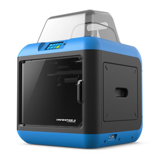
Page 10: Chapter 2: About Inventorⅱ
12. USB stick input 7. Filament cartridge 2. Touch screen button 13. USB cable input 8. Extruder 3. Nozzle 14. Power input 9. Filament intake 4. Z-axis guide rod 10. X-axis guide rod 5. Build plate InventorⅡ User Guide | www.flashforge.com 400-699-1063... - Page 11 A black plastic piece that guides the filament from the Filament Guide Tube filament box to the filament intake. Filament Cartridge A specific box for placing FlashForge filament. A solid adhesive used for making the model stick to the Solid Glue Stick build plate firmly.
- Page 12 Build Speed 10~200 mm/s Software FlashPrint Input: 3MF/ STL/OBJ/FPP/BMP/PNG/JPG/JPEG Support Formats Output: GX/G Win xp/Vista/7/8/10、Mac OS、Linux Device Size 420*420*420mm Net Weight 11.7Kg AC Input Input:100V-240VAC, 50-60Hz Power: 65W Connectivity USB cable, USB stick, WiFi InventorⅡ User Guide | www.flashforge.com 400-699-1063...
- Page 13 Delete: To delete the print file Back Print interface Abort: To abort the print job. Pause/Resume: To suspend or resume the printing job. More: To change filament and set up auto shutdown after printing. InventorⅡ User Guide | www.flashforge.com 400-699-1063...
- Page 14 The default temperature is 220℃. Tap the temperature display bar to set the temperature. To set the preheat temperature. Tap [Yes] to save the setting while tap [No] to cancel the setting. InventorⅡ User Guide | www.flashforge.com 400-699-1063...
- Page 15 X+: The extruder moves to the zero points, that is, to the right direction X-: The extruder moves to the direction opposite to the X+. Z+: The build plate elevates. Z-: The build plate descends. Back InventorⅡ User Guide | www.flashforge.com 400-699-1063...
- Page 16 Factory Reset : Return to factory setting Update: To update the firmware version. Back WiFi: Turn on WiFi: Turn on the WiFi, release the WiFi hotspot and set the WiFi on computer Back InventorⅡ User Guide | www.flashforge.com 400-699-1063...
- Page 17 ‘+’or ‘-’ to adjust the distance between the build plate and nozzle. Z:0. 00 stands for the position where the servo is precisely triggered. Status: It displays the real-time status of the extruder temperature, fan and filament. InventorⅡ User Guide | www.flashforge.com 400-699-1063...
- Page 18 About: It displays the basic information about the device. InventorⅡ User Guide | www.flashforge.com 400-699-1063...
- Page 19 Accessories Filament*1 Power Adapter Power Cable USB Cable Quick Start Guide USB Stick Screwdriver Filament Guide Tube Allen Wrench Solid Glue Stamping Wrench Unclogging Pin Tool After-sale Service Card PTFE Tube Grease InventorⅡ User Guide | www.flashforge.com 400-699-1063...
-
Page 20: Chapter 3:Unpacking
Chapter 3:Unpacking (reference video:Unpacking) This chapter will present you the whole unpacking procedure of InventorⅡ 3D printer.(Note: Make sure you read the whole unpacking guide) (3-1) Place the packaging box on a clean work surface InventorⅡ User Guide | www.flashforge.com 400-699-1063... - Page 21 USB cable, guide tube and accessory bag(USB stick*1, stamping wrench*1, unclogging pin tool*1, and screwdriver*1 Allen wrenches*2, Grease and PTFE tube.) (3-4) Remove the side protective foam sheets. InventorⅡ User Guide | www.flashforge.com 400-699-1063...
- Page 22 (3-6)Remove the top foam sheet (3-7)Remove the tape on for fixing the flat cable and cut off four ribbons that used for fixing the guide rod. Then slide the extruder to make sure the extruder is in good InventorⅡ User Guide | www.flashforge.com 400-699-1063...
- Page 23 (3-9) Take out left side foam sheet. Elevate the build plate up and then take the bottom foam sheet out. Congratulations! You have unpacked your InventorⅡ. Next, let’s move on to hardware assembly of InventorⅡ. InventorⅡ User Guide | www.flashforge.com 400-699-1063...
-
Page 24: Chapter 4: Hardware Assembly
(4-2) Take out the filament and thread it through the filament detecting equipment. (Note: The filament should feed from the bottom of the spool towards the top ) After installing the filament, put the cartridge back to the printer. InventorⅡ User Guide | www.flashforge.com 400-699-1063... -
Page 25: Printer Start-Up
For stable filament loading and proper device protection, you need to install the filament guide tube properly. (4-5) Take out the filament guide tube, thread the filament from the filament cartridge through the tube. InventorⅡ User Guide | www.flashforge.com 400-699-1063... - Page 26 (4-6) Insert the filament from the filament guide tube into the filament intake. Next, we will load the FlashForge filament.(Note: Please lower the build plate to increase the distance between the nozzle and build plate to 50mm at least for avoiding nozzle jam.)
-
Page 27: Unloading Filament
(4-10) Insert the filament into the extruder at an upright angle. Then the filament will be drawn through the extruder. Do not tap [Cancel] until the filament load the extruder steadily. 4.4 Unloading Filament 4-11 InventorⅡ User Guide | www.flashforge.com 400-699-1063... - Page 28 Note: Do not pull out the filament with force as it will damage the gears. If the melted filament has cooled down in the extruder, please repeat the steps above. InventorⅡ User Guide | www.flashforge.com 400-699-1063...
-
Page 29: Chapter 5: Build Plate Leveling
On the contrary, the distance reduces. [Tools]-[Level] (5-1) Tap on your InventorⅡ touch screen. Please wait while the extruder and platform finish initial movements. After that, operate according to the guide on the touch screen. InventorⅡ User Guide | www.flashforge.com 400-699-1063... - Page 30 If still not, please follow the prompts to adjust again till you see [OK] button. (5-5) Repeat steps 2 through 4 above to complete second and third points leveling and then Tap [Finish] to exit. InventorⅡ User Guide | www.flashforge.com 400-699-1063...
- Page 31 (7)Then move to the center of the build plate for a check. Confirm that the paper slides between the nozzle and build with a moderate amount friction. (8)Tap the [Abort] button and finish leveling. InventorⅡ User Guide | www.flashforge.com 400-699-1063...
-
Page 32: Chapter 6: About Software
Chapter 6: About Software This chapter talks about the basic function of FlashPrint. For more information about advanced function, you can browse our website www.FlashForge.com. 6.1 Software Installation 6.1.1 Software Acquisition Method 1: To get the installation package from the USB disk in the toolkit. - Page 33 Note! After starting FlashPrint, you need to select the target machine type first. When you start FlashPrint, a dialog box will pop up. Just select FlashForge Inventor Ⅱ in the machine type list and click [OK]. You can also change the machine type via [Print]--[Machine type].
- Page 34 Method 2: Select the file for loading and drag the file to the main interface of the software. Method 3: Click [File]--[Load File]. Then select the object file for loading. Method 4: Click [File]--[Examples] to load the example files Method 5: Click [File]--[Recent Files] to load the files opened recently. InventorⅡ User Guide | www.flashforge.com 400-699-1063...
- Page 35 Bottom thickness: For tube, canister and lamp to set up bottom thickness Top diameter: For tube, canister lamp and seal to set up the top diameter Bottom diameter: For tube, canister, lamp and seal to set up the bottom diameter InventorⅡ User Guide | www.flashforge.com 400-699-1063...
- Page 36 Plane (6-5) Tube(6-6) Canister (6-7) InventorⅡ User Guide | www.flashforge.com 400-699-1063...
- Page 37 Method 1: Hold down the left mouse button and drag. Method 2: Hold down the mouse wheel and scroll up and down. InventorⅡ User Guide | www.flashforge.com 400-699-1063...
- Page 38 [Reset]. ④Show Model Outline [View]--[Show Model Outline], it will highlight the yellow border of the object Click InventorⅡ User Guide | www.flashforge.com 400-699-1063...
- Page 39 In this way, you could make the model rotate on X/Y/Z axis. Method 2: Click the [Rotate] icon on the left, and then enter into rotating angel values in X/Y/Z axes positioning. Click [Reset] to reset rotating angel values. InventorⅡ User Guide | www.flashforge.com 400-699-1063...
- Page 40 6.2.8 Left-click on the model to select it and double-click on the [Cut] icon to set the cut plane. The direction and position are available for setting. ①Draw with Mouse ②X Plane InventorⅡ User Guide | www.flashforge.com 400-699-1063...
- Page 41 After loading the model, click [Edit]--[Supports] or click the Supports icon directly, then you will enter the support edit modem (as shown in the picture below). Click [Back] to exit when you finish editing. 6-10 InventorⅡ User Guide | www.flashforge.com 400-699-1063...
- Page 42 InventorⅡ User Guide | www.flashforge.com 400-699-1063...
- Page 43 Supports will be deleted once clicking the [Delete] button. Move the cursor to the supports needed deleting, current supports and its subnode support will be highlighted, click the left mouse button to delete these highlighted support. 6.2.10 Print 6-12 InventorⅡ User Guide | www.flashforge.com 400-699-1063...
- Page 44 Maximum is 0.4mm, usually the default is ok. c. Shell: Contains the outside shell value, capping layer value (under vase pattern, top solid layer setting is invalid.) ● Perimeter Shells: Maximum is 10 InventorⅡ User Guide | www.flashforge.com 400-699-1063...
- Page 45 Pause At Heights: Allows users to pre-set a height in which the print will suspend automatically. The function usually applied when you want to change the filament at a certain point. Click [Edit], then you can add or remove a height. InventorⅡ User Guide | www.flashforge.com 400-699-1063...
- Page 46 .fpp or .stl and .obj. For .stl and .boj, models are integrated as one (include support part). If load it again, only the position of the model is saved, not include the printing parameters. InventorⅡ User Guide | www.flashforge.com 400-699-1063...
- Page 47 6.2.12 Edit Menus Undo ① Allows users to undo the recent edits by the following two methods: Method 1: Click [Edit]--[Undo]. Method 2: Press the shortcut Ctrl+Z. ② Redo InventorⅡ User Guide | www.flashforge.com 400-699-1063...
- Page 48 ⑧ Repair Models [Edit]--[Repair Models] Click to repair models. ⑨ Supports Click [Edit]--[Supports] to enter supports setting interface.. InventorⅡ User Guide | www.flashforge.com 400-699-1063...
- Page 49 [Connect] Finally click button to connect to the printer. If you still can not find your machine after rescan, it means you haven’t installed the driver in the software. 6-16 InventorⅡ User Guide | www.flashforge.com 400-699-1063...
- Page 50 Click [Print]-[Connect Machine] on FlashPrint. Then the following dialog box pops up. You need to select “Wi-Fi” in Connect Mode. Enter into the IP Address shown on the interface and then click [Connect]. InventorⅡ User Guide | www.flashforge.com 400-699-1063...
- Page 51 If successfully connected, you will see the following red mark. 6-19 Disconnect InventorⅡ Click [Print]--[Disconnect] to disconnect your PC and Inventor Ⅱ. 6.2.14 Tool Menus ①Control Panel After connecting PC with Inventor Ⅱ, click [Tools]--[Control Panel] to open the control panel. 6-21 InventorⅡ User Guide | www.flashforge.com 400-699-1063...
- Page 52 Not Triggered: If the extruder/build plate don’t move to its maximum, X/Y/Z axis limit switch is not triggered, and shows “Not Triggered”. b. Triggered: If the extruder/build plate moves to its maximum, X/Y/Z axis limit switch is triggered, and shows “Triggered”. InventorⅡ User Guide | www.flashforge.com 400-699-1063...
- Page 53 It needs to cut off connection before updating firmware. If software and printer are already in connection, it reminds you [Yes] cutting off the connection, and then choose and go on to the next step. InventorⅡ User Guide | www.flashforge.com 400-699-1063...
- Page 54 When the computer and printer are in connection, click Preferences], you can check the printer name. ④ Machine information [Tools]--[Machine When the computer and printer are in connection state, click information], you can check the machine type, machine name and firmware etc. InventorⅡ User Guide | www.flashforge.com 400-699-1063...
- Page 55 ③ Check for Updates : Click [Help]--[Check for Update] to detect the available updates online. ④ About FlashPrint : Click [Help]--[About FlashPrint], the software information box will pop up. The contents include the current software version and copyright information. InventorⅡ User Guide | www.flashforge.com 400-699-1063...
-
Page 56: Chapter 7: Basic Printing
FlashForge Inventor Ⅱ (7-3)Click the [Load] icon to load a .stl model file and the object will display on the build area. [Edit]--[Surface to Platform] to make your model perfectly positioned (7-4)Click InventorⅡ User Guide | www.flashforge.com 400-699-1063... - Page 57 Note:If you’ve place your model in a right place, you can skip the step above. [Print] (7-5) Click the icon on the top, you should make some setups for your print job. Preview: If you check the [Preview] box, you can preview your model after slicing is InventorⅡ User Guide | www.flashforge.com 400-699-1063...
-
Page 58: Print Methods
USB cable and USB stick. 7.2.1 Print from Computer (USB connection) ①Connect your InventorⅡ with your PC via a USB cable. ②Turn on your InventorⅡ, level the build plate and load the filament. InventorⅡ User Guide | www.flashforge.com 400-699-1063... - Page 59 If you want to print a Gcode from a local folder, you just need to load the file into FlashPrint at the status of USB connection or WiFi connection, then click the [Print] button on the top-right. ● Load the target Gcode file into FlashPrint. InventorⅡ User Guide | www.flashforge.com 400-699-1063...
- Page 60 PC will transfer the Gcode file to the printer. 7-10 ● After finishing transferring, the printer will heat up automatically. And when heating finishes, the print will start to build the model. InventorⅡ User Guide | www.flashforge.com 400-699-1063...
- Page 61 Abort: To stop heating and printing. Once you tap [Abort], the process is irreversible. Pause:To suspend the print job, you can tap it again to resume it. You can use this function when you want to change the filament halfway. InventorⅡ User Guide | www.flashforge.com 400-699-1063...
-
Page 62: Chapter 8: Supports And Service
Chapter 8: Supports and Service FlashForge team is on standby and ready to help you with any challenges you may have with your InventorⅡ. If the issues or questions are not covered in this User Guide, you can seek for solutions on our official website or contact us via telephone. - Page 63 InventorⅡ User Guide | www.flashforge.com 400-699-1063...
Need help?
Do you have a question about the Invertor II and is the answer not in the manual?
Questions and answers