Table of Contents
Advertisement
Advertisement
Chapters
Table of Contents

Related Manuals for Flashforge Guider 3 Ultra


Summary of Contents for Flashforge Guider 3 Ultra
- Page 1 Guider 3 Ultra / 引领者 3 Ultra EN/CN-A02 User Guide 用户使用手册 中文P39...
-
Page 2: Table Of Contents
CONTENTS Notice Parameter 1. Equipment Introduction 1.1 Printer Components 1.2 Unboxing 1.3 Packing List 2. Introduction to Basic Operation 2.1 Equipment Calibration 2.2 Network Connection 2.2.1 Wired Network Connection 2.2.2 Wireless Network Connection 2.3 Filament Loading 2.4 Test Model Printing 3. - Page 3 Exposure to sunlight will accelerate the aging of plastic parts. Make sure to only use the power cord provided by Flashforge. Do not use the equipment during thunderstorms. Please turn off the equipment and unplug it if it is not in use for a long time.
- Page 4 No one is allowed to modify or translate this Guide without Flashforge's permission. This Guide is protected by copyright, and Flashforge reserves the right of the final interpretation of this Guide. First Edition (April 2023)
-
Page 5: Parameter
Parameter Equipment Name Guider 3 Ultra Extruder Quantity Printing Precision ± 0.15mm or 0.002 mm/mm [the large values shall prevail] Positioning Accuracy X/Y-axis: 0.011mm / Z-axis: 0.0025mm Layer Thickness 0.05 ~ 0.4mm Build Volume Single extrusion: 330x330x600mm Dual extrusion: 300x330x600mm Nozzle Diameter 0.4mm[default] / 0.6/0.8mm [optional]... -
Page 6: Equipment Introduction
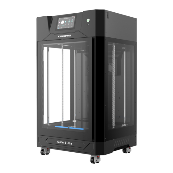
1. Equipment Introduction 1.1 Printer Components 1. Top cover 2. Extruder 3. Screen switch 4. USB port 5. Front door 6. Flexible steel plate 7. Platform plate 8. Top cover handle 9. Air filter 10. Camera 11. Chamber light 12. Filament chamber 13. -
Page 7: Unboxing
1.2 Unboxing 1. Open the top carton cover, and remove 2. Open the front door. First remove (just the top foam containing the power cord, pull out) the two pieces of rectangular user guide, USB flash drive, and after- foam below the platform. sales service card. - Page 8 5. Check the flexible steel plate for proper 6. Connect the power cord to the socket installation within the rear limit. Ensure and the printer. Press the power switch that the platform is mounted flat without to start the machine. pressing any foreign objects.
-
Page 9: Packing List
1.3 Packing List 3D Printer Power Cable Grease x 2 Glue Brush Scraper Needle-nose Pliers Diagonal Pliers Allen Wrench Set Elbow Tweezers Straight Screwdriver Unclogging Pin Tool Filament x 2 USB Disk Nozzle Assembly x 2 Heat Resistant Gloves After-sales Quick Start Guide Fuse x 2 Desiccant x 12... -
Page 10: Introduction To Basic Operation
2. Introduction to Basic Operation 2.1 Equipment Calibration Upon the first startup, please follow the on-screen instructions to perform automatic Z-axis calibration and platform leveling. Then, there is no need for calibration during regular printing. However, it is recommended to perform Z-axis calibration and platform leveling after the nozzle or platform is replaced. - Page 11 3. Once Z-axis calibration is completed, click the icon to enter the "Leveling" interface. Before leveling, you can choose to use the same leveling data for each print or perform automatic leveling before each print. After confirming, click [Leveling] to enter the leveling preparation interface.
-
Page 12: Network Connection
2.2 Network Connection 2.2.1 Wired Network Connection 1. Insert the network cable into the Ethernet port on the back of the printer. 2. Click the [ ] icon to enter the [Network] interface, select [Ethernet], and enable the Ethernet function. 3. -
Page 13: Filament Loading
2.3 Filament Loading When loading filament, please pay attention to the left and right Note corresponding labels on the extruder, filament guide tube, and filament chamber. 1. After unpacking the new filament, cut the 2. Open the filament chamber and bent end with diagonal pliers. - Page 14 5. Click the [ ] icon, enter the [Filament loading] interface, select the corresponding extruder and material, and then click [Load]. 6. Successful filament extrusion from the nozzle indicates successful loading.
-
Page 15: Test Model Printing
2.4 Test Model Printing 1. Click the [ ] icon on the left to enter the [Printing] interface. Inside the machine, there are three test models: Test L.gx (left-extruder printing test model), Test R.gx (right- extruder printing test model), and Test L+R.gx (dual-extruder printing test model). 2. -
Page 16: Introduction To User Interface
3. Introduction to User Interface The interface layout may change whenever there is an Note upgrade of firmware. The following is only a brief overview of the functions. 3.1 Main Interface Main interface when the printer is idle Main interface Printing interface Settings interface Filament interface... -
Page 17: Printing Interface
Filament loading status Adjust the speed of the left-nozzle model cooling fan Number of layers Adjust the speed of the right-nozzle model cooling fan Real-time extruder moving speed Adjust the speed of the auxiliary Infill percentage model cooling fan Adjust the printing efficiency Filter fan switch by percentage Adjust the Z-axis distance between... -
Page 18: Settings Interface
3.3 Settings Interface Click the [ ] icon on the left to enter the settings interface. Top icons from left to right are: [Move] Extruder; Platform; Chamber Preheating; Fan Settings; Manual XYZ-axis Movement; Chamber Light Switch; [Network] Wireless Network, Wired Network, Hotspot; [Cloud Platform] Connect to FlashCloud or Polar Cloud;... -
Page 19: Filament Interface
3.4 Filament Interface Click the [ ] icon on the left to enter the filament interface. During filament loading and unloading, users can choose the filament based on their needs. If the required filament is not listed in the interface, users can customize it and set the required temperature for loading. -
Page 20: Information Interface
Extruder calibration and platform leveling can be carried out here. Top icons from left to right are: [Auto Z-axis Calibration] Automatically calibrate the extruder's Z-axis travel and the height difference between the left and right nozzles; [Auto Leveling] Automatic platform leveling; [XY Offset] Calibrate the XY offset of the left and right nozzles;... -
Page 21: Model Printing
Method 1: Find the FlashPrint software package on the USB flash drive and install the version that matches your system. Method 2: Download the latest slicing software from the official English website at www.flashforge.com. 3D Printing Process: Obtain the model file (in stl/obj/stp format) - Import the file into the slicing software... -
Page 22: Dual-Extruder Printing Mode
4.3 Dual-Extruder Printing Mode For the first dual-extruder printing, please perform XY offset calibration Note of the left and right nozzles to align the right nozzle with the left one. Before calibrating, load filaments into both the left and right extruders and ensure they can extrude filament properly (refer to Section 2.3). - Page 23 4. Once the XY offset calibration is completed, you can start dual-extruder printing. 5. Open FlashPrint, load the model, click the [ ] icon, and then select the support type. 6. Click [Auto Supports]. 7. Click the [ ] icon, left-click the support, press "Ctrl+A" to select all supports, and then right-click to choose a specific extruder for printing supports.
-
Page 24: File Transfer Via Network
4.4 File Transfer via Network 1. After connecting to the network, open FlashPrint. Click the icon at the lower left corner, select [Machine Type], select [Guider 3 Ultra], and then click [Print] - [Connect Machine]. 2. In the pop-up box, select the connection method: enter the printer's IP address or use automatic scanning. -
Page 25: File Transfer Via Usb
3. After slicing is completed, click [Send To Printer]. The printer will begin preheating, and then automatically start printing after it is ready. Note: The printer and the computer must be connected to the same network. Otherwise, connection will fail. 4.5 File Transfer via USB 1. -
Page 26: Cloud Printing
After clicking [OK], the information will appear on the printer's FlashCloud interface. FlashCloud The current printer is empty. Please add a printer. Home My Printer Add printer Register code Type State My Printer Guider 3 Ultra ABCDEF Guider 3 Ultra Idle My Model My Job Model Library... - Page 27 Model Library Print 4. The drop-down menu for the printer name allows you to select the printer for performing this print job. (The printer must be added to My Printer). FlashCloud Home Flashforge Edit model Print para My Printer Move Rotate...
- Page 28 5. Finally, click [Start], and the selected printer will automatically start the print job. FlashCloud Home Flashforge My Printer Time Remaining My Model My Job Model Library 21℃/0℃ 21℃/0℃ Closed Nomal Start Cancel Printing via Polar Cloud 1. Open the Polar Cloud website and register an account.
- Page 29 3. After connecting Guider 3 Ultra to the network, enter the cloud platform interface (click the Settings icon -> Cloud Platform icon). Turn on the Polar Cloud switch (it should display green). Enter the account and PIN code, and then click [Save].
- Page 30 8. Click [PRINT]. 9. Click [START], and the printer will begin downloading the cloud task and start printing once the download is completed.
-
Page 31: Camera Connection
4.7 Camera Connection 1. Turn on the camera switch. Click the [ ] icon, access the [Camera] interface, and enable both [Camera] and [Video] functions. 2. When the printer is connected to FlashPrint, you can watch real-time videos via FlashPrint's [Multi-Machine Control]. The camera function is also available in FlashCloud and Polar Cloud. - Page 32 To install the platform plate back, follow these steps: 1. Put the rear end of the flexible steel plate against the positioning blocks on the left and right edges of the platform; Make sure to insert it into the inside of the slots.
-
Page 33: Maintenance
5. Maintenance The interface layout may change whenever there is Note an upgrade of firmware. The following is only a brief overview of the functions. 5.1 Extruder Maintenance 5.1.1 Nozzle Assembly Replacement Note Before operating it, please first unload the filament and then disconnect the power. - Page 34 Note If filament is stuck and cannot be removed from the extrusion box, you can disassemble the extrusion box and remove the filament. Here are the steps: Cut the zip ties on the extrusion box. Remove the two screws on the magnetic holder and the four screws that fix the extrusion box.
-
Page 35: Platform Flatness Calibration
In this case, initial platform leveling is required. You can contact Flashforge's customer support for remote calibration Note assistance. Please operate as follows: There are four leveling points in total. - Page 36 For the initial placement of the platform plate, you can use a vernier caliper or 16mm equal-height blocks to confirm the distance between the platform sticker and the profile at the four corners.
-
Page 37: Q&A
6. Q&A Q1: Is calibration required after nozzle replacement? Yes. Q2: What to do if the extruder moves but doesn't extrude filament at the beginning of printing after clicking the model for printing? 1. Observe the filament guide tube to check if filament has entered the nozzle. If not, please click [Load] until filament comes out. - Page 38 Q8: Is it necessary to add a raft when printing models? Not necessarily. Adding a raft results in more filament extrusion and higher print success rate. With a heated build plate, it enhances the adhesion between the model and the platform, which makes the model adhere to the platform well during printing, and also increases the print success rate.
-
Page 39: Help And Support
Many questions are answered at Flashforge's English official website - www.flashforge.com. Flashforge's after-sales service team can be reached by phone from 8:00 AM to 5:00 PM, from Monday to Saturday. In case you contact us during off-duty time, your inquiry will be answered the next working day immediately. - Page 40 目录 注意事项 设备参数 1. 设备简介 1.1 整机介绍 1.2 机器开箱 1.3 装箱清单 2. 基础操作介绍 2.1 校准设备 2.2 网络连接 2.2.1 有线网络连接 2.2.2 无线网络连接 2.3 安装丝料 2.4 测试模型打印 3. 设备操控界面简介 3.1 主界面 3.2 打印界面 3.3 设置界面 3.4 丝料界面 3.5 调平校准界面 3.6 信息界面 4. 打印模型 4.1 切片软件安装...
- Page 41 注意事项 安全提示:请确保认真阅读以下安全提示 工作环境安全 请保证打印机的工作台面干净整洁。 请保证打印机工作时远离可燃性气体、液体及灰尘。设备运行产生的高温有可能会与 空气中的粉尘、液体、可燃性气体反应引发火灾。 儿童及未经培训的人员请勿单独操作设备。 用电操作安全 请务必将设备接地;切勿改装设备的插头。未接地 / 未正确接地 / 改装插头必然会增加 漏电风险。 请勿将设备暴露在潮湿或烈日的环境中。潮湿的环境会增加漏电的风险 / 暴晒会加速塑 件老化。 请勿滥用电源线,务必使用闪铸科技提供的电源线。 切勿在雷雨天气使用设备。 如长时间不使用设备,请关闭设备并拔下电源线插头。 个人操作安全 在设备运行时,请勿触碰喷头、平台等位置! 请勿触碰喷头与平台,以免高温烫伤或机械损伤! 在操作设备时,请勿穿戴围巾、口罩、手套、珠宝装饰等容易卷入设备的物件! 请勿在饮酒、服药之后操作设备! 设备使用提示 保持设备内部整洁,切勿将金属物体掉入打印平台底部的滑槽内! 请及时清理丝料碎屑,建议在设备外进行操作! 自行对设备进行任何改装将不再享有保修权利! 请在设备进丝操作时,喷头和平台的距离至少保持50mm的距离。距离过近,有可能 会造成喷头堵塞。 请在通风的环境下操作设备! 请勿利用该设备进行违法犯罪的活动! 请勿利用该设备制作食物储存类产品! 请勿将打印模型放入口腔!...
- Page 42 设备运行环境要求 室内温度在15-30度为宜;湿度在20%-70%为宜 设备放置要求 设备需要被放置于干燥通风的环境中。设备前后左右四周必须预留至少60cm的空间距离。 存储温度在0-40℃为宜。 设备兼容耗材要求 在使用该设备时,建议使用闪铸科技的耗材。如使用非闪铸科技的耗材,材料特性有一定 差异,打印参数可能需要调整。 耗材存储要求 耗材拆封后请保持耗材的储存环境干燥及无尘,建议使用配套干燥盒存储。 法律申明 用户无权对此使用手册进行任何修改。 客户若自行拆装或改造设备造成任何安全事故,闪铸科技概不负责。未经闪铸科技 允许,任何人不得对该手册进行修改或翻译。本手册受版权保护,闪铸科技对本手 册保留最终解释权。 第一版(2023年4月) @Copyright 2022 浙江闪铸三维科技有限公司版权所有...
- Page 43 设备参数 设备名称 引领者 3 Ultra 喷头数量 打印精度 ± 0.15mm 或 0.002 mm/mm [以较大值为准] 定位精度 X/Y轴:0.011mm Z轴:0.0025mm 层厚度 0.05 ~ 0.4mm 打印尺寸 单喷头 330x330x600mm;双喷头 300x330x600mm 喷嘴口径 默认0.4mm [可选0.6/0.8mm] 喷嘴类型 高强喷嘴 打印速度 10 ~ 500mm/s 最高喷头温度 350℃ 平台最高温度 120℃ 支持耗材类型 PLA/PETG/ASA/ABS/PC/PA/PLA-CF PETG-CF/PETG-GF/PA-CF/PA-GF 电...
-
Page 44: 设备简介
第 一 章:设备 简介 1.1 整机介绍 1. 上盖 2. 喷头 3. 屏幕开关 4. USB接口 5. 前门 6. 柔性钢板 7. 平台板 8. 上盖把手 9. 空气过滤 10. 摄像头 11. 腔体灯 12. 耗材仓 13. 耗材仓湿度计 14. 干燥剂放置处 15. 驱动板散热孔 16. 电源开关 17. 电源接口 18. -
Page 45: 机器开箱
1.2 机器开箱 1. 拆开顶部纸盖后,取出机器顶部泡沫,內有 2. 打开设备前门,首先取出(拉出即可)平台 电源线、用户手册、U盘和售后服务卡。再 下方最上面的两根方型泡沫棉。 从下往上将整个外箱取出,然后将机器搬离 木制底座。 方型泡沫棉 方型泡沫棉 3. 随后取出平台下方的其余泡沫棉,共2层, 上层为工具配件包;下层为附赠耗材、高 温手套、干燥剂。(详细参考装箱清单)。 4. 使用斜口钳减去固定喷头 和导轨上的扎带。移除后 能正常移动喷头即可。... - Page 46 5. 检查机器平台柔性钢板是否安装到位,是否 6. 将电源线连接插座与设备,轻触电源 已安装在后方限位内。确保平台安装平整, 开关按钮,启动机器。 没有压到任何异物。 电源开关 7. 按下屏幕开关,按钮灯长亮表示已开启触控屏。 8. 首次开机将进入开机引导界面,按引导提 示操作可使打印机快速调整至打印准备就 绪状态。 提 示 设备首次开机可按开机引导进行一次设备打印测试确认,用于确认设备能正常运行。 开进引导步骤如下:确认机器语言 - 校准和调平设备 - 装载丝料 - 设备准备就绪 - 测试文件打印 - 打印完成;若跳过了该开机引导中的步骤,仍可以在屏幕中选择对应的功能项进行操作。 备注:需再次进入开机引导可以点击触控屏左侧的 图标进入[信息]界面,点击[恢复出厂设置], 选择[是],重启设备后即可重新进入开机引导界面。...
-
Page 47: 装箱清单
1.3 装箱清单 3D 打印机 电源线 润滑脂 x 2 水洗胶 毛 刷 铲 刀 尖嘴钳 斜口钳 一字螺丝刀 通 针 内六角扳手套装 弯头镊子 喷嘴组件 x 2 隔热手套 3D打印耗材 U盘 售后服务卡 快速启动指南 保险丝 x 2 干燥剂 x 12 柔性钢板平台... -
Page 48: 基础操作介绍
第 二 章:基础操作介绍 2.1 校准设备 首次开机进入开机引导,将会引导操作进行自动Z轴校准和平台调平,请根据界面指示操作。平时 打印无需再执行校准和调平操作。如果您更换了喷头或者平台板后建议做一次Z轴校准和平台调平。 校准和调平前请先清理喷嘴和平台板,确保无残留丝料或异物。设备进行校准 注意事项 调平时请不要移动或碰撞机器。 按如下顺序进行操作: 1. 进入校准界面后,在触控屏上点击图标 进入“自动Z轴校准”,点击[开始], 打印机会自动校准 喷头与平台的Z轴间距以及左右喷嘴的高度差。 2. 自动校准完成后设备会自动保存校准数据,如果数据有异常设备会提示您重新检查设备,确认后 点击按钮[重新校准]设备会再次进行自动Z轴校准。... - Page 49 3. Z轴校准完毕后,点击图标 进入“调平”界面,调平前可以选择使用同一个调平数据应用 到每次打印的过程中,或者每次打印模型前都进行一次自动调平。确认后点击[调平]按钮, 进入调平准备界面,确认好平台板已安装到位并且喷嘴和平台板都清理干净后点击[开始], 设备会自动进行平台调平。 4. 调平结束后如数值无异常,设备会自动保存此次调平数据,如有异常可以按界面的提示信息 重新检查设备,确认后点击[重新调平],设备会再次进行调平工作。 提 示 设备在打印过程中无法进入校准界面和进丝界面。 5. 喷头共振补偿功能在设备出厂前已经做过校准,一般情况下无需再次进行操作。当您发现模型 打印完成后表面有振纹的情况下可进行一次操作,操作前请先阅读共振补偿界面的提示,以保 证校准可以正常完成。点击[开始]按钮后,设备会自动进行校准,校准过程中产生震动及轻微 响声为正常现象。...
-
Page 50: 网络连接
2.2 网络连接 2.2.1 有线网络连接 1. 将网线插入设备背部的网线接口。 2. 在屏幕上点击图标 [设置] - 进入[网络]界面,选择以太网,开启以太网功能。 3. 若屏幕右上角出现 图标, 则表明设备已经成功连接网络。 2.2.2 无线网络连接 连接无线网络前,需要开启Wi-Fi功能,否则将无法收到无线信号。 1. 在屏幕上点击图标 [设置] - 进入[网络]界面,选择无线网络。 2. 点击连接对应无线网络,若屏幕右上角出现 图标,则表明设备已经成功连接网络。... -
Page 51: 安装丝料
2.3 安装丝料 注意事项 装载丝料时,请注意喷头、导丝管和耗材舱上左、右对应的标贴提示。 1. 新耗材拆包后,用斜口钳剪去耗材前端的折弯 2. 打开耗材舱,手动将丝料穿过舱内上方 部分。 对应的丝料传感器,直至从导丝管另一 端看到丝料。(注意标贴提示对应的喷头 和孔位)。 3. 将喷头端导丝管延伸出的丝料,插入对应进丝 4. 最后将丝料放入耗材舱,此处可将随机 口,推入送丝轮内,感受到一定阻力时即可, 附赠的干燥剂放在料仓下方的卡槽内。 或按压进丝把手,将丝料推入送丝轮内卡住。 关上料舱盖子。[注:为方便耗材转动顺 畅,对应左喷嘴的丝料放置时按顺时针 方向捋顺丝料,对应右喷嘴的丝料放置 时按逆时针方向捋顺丝料] 干燥剂卡槽... - Page 52 5. 在屏幕上点击[ 丝料],进入[进丝]界面,选择准备进丝的喷头和对应的材料,点开始 进丝, 界面如下。 6. 当喷嘴开始吐出丝料,即为进丝完成。...
-
Page 53: 测试模型打印
2.4 测试模型打印 1. 在触控屏左侧点击 图标进入打印界面,机器设备内会有三个测试模型,分别是Test L.gx(左 喷头测试模型)、Test R.gx(右喷头测试模型)、Test L+R.gx(双头打印测试模型)。 2. 打印前先确认准备测试的模型对应的喷嘴已装载丝料,然后选择模型文件,再点击 图标 即可开始打印。 开机引导默认是左喷头加载丝料,所以请选择Test L.gx(左喷头测试模型)进行 注意事项 打印测试。如需打印Test R.gx(右喷头测试模型)和Test L+R.gx(双喷头测试 模型),请先将对应的喷头加载丝料后再进行测试,并且在首次使用双喷头打 印前,先进行一次左右喷嘴XY轴偏移值校准,参考步骤4.3双头打印。... -
Page 54: 设备操控界面简介
第 三 章:设备 操控界面简介 因固件会不定期升级,UI界面请以实际 注意事项 显示页面为准,以下仅为功能简介。 3.1 主界面 机器闲置时主界面显示状态信息 主页 打印 设置 丝料 校准 信息 机器打印时主界面显示模型打印状态信息... -
Page 55: 打印界面
丝料加载状态 调整左喷嘴模型冷却风扇速率 模型分层层数 调整右喷嘴模型冷却风扇速率 喷头实时的移动速度 调整模型辅助散热风扇速率 模型内部填充率 空气过滤风扇开关 百分率调整打印效率 调整喷头和平台间的Z轴距离 3.2 打印界面 点击左侧 图标进入打印界面。 点击要打印的模型。 在弹出框点击 图标开始打印。 [本地] 本地模型打印文件列表 [字母排序] 按文件首字母进行排序 [U盘] U盘内模型打印文件列表 [时间排序] 按文件修改时间进行排序... -
Page 56: 设置界面
3.3 设置界面 点击左侧 图标进入设置界面。 顶部图标从左到右依次是: [移动]喷头、平台、腔体预热,风扇设置,手动移动设备XYZ轴,腔体灯开关 [网络]无线网络,有线网络,热点 [云平台]连接闪铸云、Polar平台 [摄像头]打开摄像头与延时视频、查看视频和照片 工具页面图标 空气过滤风扇开关 左喷嘴温度设置 ℃ 腔体灯开关 右喷嘴温度设置 ℃ 打印完成后自动关机开关 平台温度设置 ℃ 左喷嘴丝料检测开关 左喷嘴丝料加载状态 右喷嘴丝料检测开关 右喷嘴丝料加载状态 喷头和平台回到初始位置... -
Page 57: 丝料界面
3.4 丝料界面 点击左侧 图标进入丝料界面。 进丝与退丝时,用户可根据实际需要安装的丝料进行选择,若界面中无当前所需的丝料,用户 可以自定义丝料,设置进丝时所需的温度。如需更换耗材,可以参考喷头清洗界面提示进行操作。 丝料界面包含: 进丝操作界面 退丝操作界面 耗材更换帮助界面 3.5 调平校准界面 点击左侧 图标进入调平校准界面。 在校准界面中可进行喷头校准和平台调平,图标从左到右依次是: [Z轴自动校准] 自动校准喷头Z轴行程和左右喷嘴的高度差; [自动调平] 自动调平平台; [XY轴校准] 左右喷嘴XY轴偏移值校准; [专家模式] 手动调整右喷头相对左喷头XYZ轴的偏移值。 [共振补偿] 对喷头进行共振测量和自动整形校正。... -
Page 58: 信息界面
3.6 信息界面 点击左侧 图标进入信息界面。 [升级]固件升级,可在无线网络连接时,升级到设备最新的固件。 [拷贝日志]将日志拷贝到U盘。 [打印机名称]修改机器名称。 [语言]设置打印机系统语言。 [恢复出厂设置]将系统中的各项设置恢复到出厂状态... -
Page 59: 打印模型
第 四 章:打印模型 4.1 切片软件安装 方法一 :在U盘中找到 FlashPrint 软件安装包,选择对应的系统版本进行安装。 方法二:从中文官方网站 www.sz3dp.com 下载最新的切片软件。 3D 打印过程: 获取模型文件(stl/obj/stp 格式)-文件导入切片软件-使用切片软件进行切片-设备准备 就绪-文件传输至打印机打印。 注:可在安装切片软件后,在切片软件中查看切片软件的使用说明。 4.2 单头模式打印 单头模式打印默认使用左喷头打印,因为左喷头是固定头,右喷头是升降头, 注意事项 左喷头打印模型会优于右喷头。打印前,请先确认喷头已加载丝料,并可正常 挤出耗材,可参考2.3。 打开切片软件后,请在左下角选择您所使用的打印机机型,然后在切片软件中导入模型。用户 可对模型进行移动、旋转、缩放等修改;设置好摆放方式后在软件界面点击 [支撑]图标, 选择支撑类型,点击自动支撑。返回到主界面再点击[开始切片],选择对应的打印材料后点击 [切片]生成切片文件。... -
Page 60: 双头模式打印
4.3 双头模式打印 如果是首次进行双头模式打印,请进行一次左右喷嘴XY轴偏移值校准,该步骤 注意事项 的目的是校准右喷嘴的 XY 间距从而与左喷嘴对齐。在校准操作前,请先将您的 左右喷头各加载一卷耗材,并且确保左右喷嘴能够正常挤出耗材,可参考2.3。 双头异支撑打印时,建议选择左喷头打印模型部分,右喷头打印支撑部分,原因 参考单头打印的[注意]说明。 1. 进入校准调平界面,在触控屏上点击图标 进入[XY轴校准]界面,点击[开始]后,打印机 会自动加温,到达目标温度后左右喷嘴会在XY方向上各打印一条测试线。 2. 打印完成后,可以用尺子测量实际打印同方向两条线的偏差距离。将打印的测试线与屏幕 上的示例进行比较。对照示例的提示进行右喷嘴XY间距的调整。 3. 调整完后点击[验证]按钮再次打印测试线,如果还存在偏移情况,请重新执行步骤“4.3-2” 的操作。当实际打印线如下图所示,说明左右喷嘴 XYZ 方向偏移值在合理的范围内点击 [完成]保存数据。... - Page 61 4. 左右喷嘴XY轴偏移值校准完成后,即可开始双头模式打印。 5. 打开FlashPrint软件后载入模型,在软件界面点击 [支撑]图标,选择支撑类型。 6. 点击[自动支撑]。 7. 选择 图标,鼠标左键点击支撑,按“Ctrl+A”全选支撑,再按鼠标右键可以选择 需要用来打印支撑材料的喷头,选好后点击[返回]。...
-
Page 62: 文件传输:网络传输
8. 点击界面上方的[开始切片],进入参数配置页面。 9. 选择配置材料(例如使用右喷头打印PLA模型,使用左喷头打印PVA支撑)。 10. 点击[切片],生成切片文件。 双喷头打印模型时时建议添加围墙或者擦嘴塔,以刮除空闲喷嘴的漏丝。 注意事项 更多打印配置可点击[帮助]-选择[帮助文档]查看。 4.4 文件传输:网络传输 1. 连接网络后,打开FlashPrint切片软件,点击界面左下角图标选择[机器类型],选择 [Guider 3 Ultra]机型,然后点击[打印] - [连接机器]。 2. 在弹出的对话框中,连接方式选择IP端口一栏中填入 打印机的IP地址或自动扫描。IP地址可以在机器的信 息界面查看。输入完成点击连接。连接成功直接弹出 [多机控制]界面, 可查看打印机连接状态。... -
Page 63: 文件传输:Usb传输
3. 模型切片完成后点击[发送至打印机]。打印机开始进行预热等准备工作,准备完成后自动 开始打印。 提示:打印机连接的网络和电脑连接的网络必须在同一个网段中,否则连接不成功。 4.5 文件传输:USB传输 1. 设备也可通过U盘打印。将切片好的文件(*.g/*.gx/*.gcode格式)保存至U盘。 2. 将U盘插入设备USB接口。 3. 进入[打印]界面,在触控屏上点击图标 进入U盘文件界面,选择对应的文件即可打印。... -
Page 64: 云打印
4.6 云打印 闪铸云打印 1. 打开闪铸云网站,注册账号,经过邮箱激活后,即可登录使用。 闪铸云:https://cloud.sz3dp.com 2. 点击 [我的打印机] - [添加打印机]。 在添加打印机页面填写注册号[云注册码],为打印机起个名字,点击确定后,这些信息会出现 在打印机的闪铸云界面。 首页 我的打印机 添加打印机 当前打印机为空,请添加打印机 注册号 类型 状态 我的打印机 Guider 3 Ultra XXXXXX Guider 3 Ultra 空闲 我的模型 我的任务 模型库... - Page 65 3. 在模型库中选择一个模型,或上传自己的模型文件(STL文件),点击打印进入模型简易 编辑界面。 首页 User 2023.3.3 我的打印机 3D打印支架 模型详情 我的模型 我的任务 模型库 打印 4. 在打印机名称的下拉菜单中,可以选择希望执行本次打印任务的打印机。(打印机必须被添加 进我的打印机)。 Flashforge 首页 编辑模型 打印参数 我的打印机 移动 旋转 缩放 我的模型 -150 我的任务 模型库 -150 -150 打印...
- Page 66 5. 最后点击开始,被选中的打印机会自动开始执行本次打印操作。 首页 Flashforge 剩余时间 我的打印机 我的模型 我的任务 模型库 21℃/0℃ 21℃/0℃ 关闭 正常 开始 取消 Polar云打印 1. 打开Polar云网站,注册账号。Polar云: https//Polar 3d.com 2. 登录后,点击右上角头像图标,点击[Settings],在页面下方找到PIN Code一栏,显示的 数字就是PIN码。 Location Biography Website URL http://www.example.com/profile Email +ADD Email PIN Code xxxx...
- Page 67 3. 将Guider 3 Ultra连接网络后,进入云平台界面(点击设置->云平台),打开Polar云开关 (Polar云打开后开关应显示为绿色)。在下方的账号和PIN码栏中分别填入之前注册Polar云 时填写的账号与之前查询得到的PIN码,点击保存。 4. 连接完成后,在Polar云网站首页就可以看到打印机的信息。 5. 在网站首页上方的菜单栏中点击[Explore],选择下拉列表中的[Objects]。 6. 点击[MY OBJECTS],然后点击[UPLOAD]上传模型。 7. 将需要上传的模型文件拖拽至框型区域或点击框型区域后选择上传模型,然后点击 [UPLOAD] 上传。...
- Page 68 8. 点击[PRINT]。 9. 点击[START],打印机开始云任务下载,下载完成后开始打印。...
-
Page 69: 摄像头连接查看
4.7 摄像头连接查看 1. 打开摄像头开关,在触控屏上点击图标 [设置] - 进入[摄像头]界面,将[相机]和[视频] 功能打开。 相机 视频 图片 视频 2. 设备与FlashPrint连接后可以在FlashPrint -[多机控制]中查看到实时视频画面。在闪铸云 和Polar云也可使用摄像头的功能。 4.8 打印后模型移除 警 告 从打印平台上移除模型时,请注意需要等待平台冷却后再操作。此时可查看屏幕 顶部状态栏温度图标来确认平台温度,绿色图标表示平台温度低于50℃,可进行 安全操作。 移除模型时可以使用配套手套,同时务必注意设备高温。 打印完成后,将平台板前部2个锁扣 逆时针转动至松动,取出整个平台板, 将平台板折弯即可取下模型。... - Page 70 取下模型重新将平台板放回设备,操作如下: 1. 将柔性钢板后端顶住平台左右边缘的定位块;注意要插入卡槽内侧。 2. 合上锁扣直至固定住柔性钢板。...
-
Page 71: 维 护
第 五 章:维护 因固件会不定期升级,UI界面请以实际 注意事项 显示页面为准,以下仅为功能简介。 5.1 喷头维护 5.1.1 喷嘴组件更换 注意事项 操作喷头前,需先退出喷头内的丝料,再断开电源。 喷嘴组件卡扣 1. 打开磁吸式的喷头前盖。 2. 拨动喷嘴组件卡扣,取出 喷嘴组件。 3. 将新的喷嘴组件安装上去, 扣紧喷嘴组件卡扣。 5.1.2 喷头堵头清理 方法一:预热喷头,喷头加热至所使用材料温度,拔出导丝管,按压把手,拔出丝料, 将通针插入喷嘴内部进行疏通。 方法二:方法一操作无效,参考喷嘴组件拆装方式更换喷嘴组件。... - Page 72 提 示 如遇到丝料卡挤出盒取不出,可以拆卸挤出盒取出丝料。 操作如下: 剪去挤出盒上的扎带,将磁铁吸合座上的螺两个螺丝和固定挤出盒的四个螺丝 拧下,往外拉出挤出盒(必要时拧开热端把手将热端一起拆下)。将挤出盒里面的 卡料取出后重新安装挤出盒(下图为挤出盒零件示意图)。注意安装挤出盒时,可 以先拆掉喷嘴组件,将轴承先对准挤出盒基座再按压把手使把手转轴插入对应孔, 最后拧上挤出盒固定螺丝,重新安装上挤出盒磁铁吸合座并拧上螺丝,最后取新 的轧带将线束固定好即可。 挤出盒固定螺丝 磁铁吸合座 导料管 轴承 送丝轮 挤出把手 把手转轴 把手弹簧 电机减速轮 把手弹簧座 送丝轮转轴...
-
Page 73: 平台平面度校准
5.2 平台平面度校准 用户一般无需进行此操作,当设备平面度经过各种校准或者自动调平补偿无效的时候,可能是 平台安装的平面度已受到破坏,此时需要进行初始的平台调平。 此操作可联系闪铸科技售后人员,进行远程协助校准。 特别提示 操作如下:总计调平点位置4个。 注意事项 此步骤请谨慎操作,或可联系专业工程师指导。 1. 通过移动平台高度调整到合适的视野位置; 2. 检查平台底部应变片线不被压死; 3. 锁紧四个顶丝旁边的M5螺丝(锁紧过程中需要两边同时锁紧,请勿单边拧死后在拧另一次); 4. 标定柔性钢板贴纸面到型材面之间的距离为16mm(通过手拧底部四个顶丝),四个角都一致。 锁紧螺丝 锁紧螺丝 锁紧螺丝 顶丝 锁紧螺丝 锁紧螺丝 顶丝 锁紧螺丝 锁紧螺丝 顶丝 锁紧螺丝 顶丝 再放置平台板以及初次标定16mm距离后, 通过拧中间四个螺丝来调整平台平整度,待 平整度调整完后,锁紧中间顶丝旁的锁紧 螺丝来锁紧,拧锁紧螺丝过程中必须两边 同时拧,不可单边拧紧后再拧另一边。... - Page 74 平台板初次放置,可用游标卡尺或16mm等高块 标定四个角处的平台贴纸到型材间的距离。...
-
Page 75: Q&A
第 六 章:Q&A Q1:更换喷嘴后需要校准设备吗? 需要。 Q2:点击打印模型,喷头运动,但打印一开始就没有出丝怎么办? 1. 观察导丝管,确认丝料是否已进入喷头,若无,请再点击进丝按钮,直至丝料从喷头 中吐出; 2.查看喷头是否堵头,若是,解决方案请查看5.1.2。 Q3:打印时发现喷嘴与平台相对位置过高[远离平台]或过低[顶到平台] 怎么办?如何调平? 解决方案查看2.1-校准设备。 Q4:可以使用其他品牌的丝料吗? 可以使用其他品牌丝料,但由于不同材料参数温度略有区别,需要经过参数调整配置。 Q5:产品打印完成后可以自动关机吗? 可以。在[设置]页面中打开该功能即可。 Q6:打印ABS材料安全吗? ABS在加热过程中会释放有毒气体,建议打印时或打印后开启HEPA空气过滤器进行过 滤。如条件允许,建议将设备置放在开阔环境下打印。儿童活动场所建议打印PLA无毒 材料。 Q7:打印模型发生翘边或粘不牢现象怎么办? 方案1:增加平台温度可有效缓解此问题,高温可增加平台与模型的粘附力。 方案2:模型切片时选择添加底板可有效缓解此问题。 方案3:涂抹胶水。 方案4:喷嘴与平台的间隙过大,可相应减小间隙,使用喷头校准专家模式或调平校 准功能进行间隙调整。 方案5:确认平台是否放平。可使用调平校准功能,建议执行完全流程的自动调平。... - Page 76 Q8:打印模型时必须要增加底板吗? 不一定。打印底板时出丝量较多,打印成功率较高。在底板加热的条件下,模型与平 台板的粘附性增加,使模型打印时能很好的粘附在平台上,同样也能增加打印成功率。 Q9:插入U盘后找不到打印文件,屏幕显示全为文件夹怎么办? U盘格式不正确,设备支持FAT32格式的文件系统,请将U盘格式化成FAT32格式。 Q10:Wi-Fi连接不上怎么办? 1. 请检查Wi-Fi名称是否含有特殊字符,如果有,请修改之后再次尝试; 2. 请检查密码是否含有特殊字符,如果有,请修改之后再次尝试。 Q11:更新固件注意事项。 请不要在下载或更新固件时断电断网,防止更新失败。 Q12:为什么开机屏幕白屏? 如果听到开机声音,请更换屏幕或者排线;否则请联系售后人员。 Q13:耗材舱湿度计使用的电池是否配置?型号多少? 电池需自己购买,型号LR44,1.5V,尺寸11.6*5.1mm。 兼容型号:AG13/A76/L1154。...
-
Page 77: 帮助与支持
第 七 章:帮助与支持 闪铸专业的售后服务人员及业务员随时为您待命,非常乐意为您解决在您使用过程中遇到的任 何问题。如果您无法从用户手册中找到答案,您可以进入我们的官方网站来搜索问题的解决方 案,或者通过电话联系我们。 在我们的官网中可以找到一些常见问题的说明和解决方法。您的许多问题都可以在闪铸科技中 文官方网站www.sz3dp.com得到解决。 您可以在周一到周六上午8:00到下午5:00通过电话来联系闪铸售后团队,为您解决问题。如果 您在下班时间联系我们,闪铸将在下个工作日的第一时间给您反馈。若造成不便,我们万分抱歉。 由于更换不同的丝料,会有少量杂质残留在喷头中造成喷头堵塞,疏通后即可, 提 示 不属于质量问题。若用户使用时存在该问题,请联系售后,并在售后的指导下 完成疏通工作。 售后服务热线:400-886-6023 邮箱:support@flashforge.com 公司地址:浙江省金华市婺城区仙源路518号 提示:联系售后时,请提供产品序列号,即打印机背部的条形码 S/N: FFAD******...
Need help?
Do you have a question about the Guider 3 Ultra and is the answer not in the manual?
Questions and answers