
Related Manuals for Flashforge Inventor


Summary of Contents for Flashforge Inventor
- Page 1 Flashforge Corporation Flashforge Inventor 3D Printer User Guide Inventor User Guide | www.flashforge.com 0086- 0579-82273989...
-
Page 2: Table Of Contents
Content..........................2 Introduction........................5 Notice..........................6 Chapter 1: 3D Printing Technology.................9 1.1 Process........................9 Chapter 2 . About Inventor.................... 11 2.1 About Your Inventor..................11 2.1.1 Main view:.....................11 Chapter 3. Unpacking....................15 Chapter 4 . Hardware Assembly..................17 4.1 Mounting the Extruder Set................18 4.2 Installing Filament....................19... - Page 3 Flashforge Inventor. Even if you are familiar with earlier Flashforge machines or 3D printing technology, we still recommend that you read through this guide, as there is lots of important information about the Inventor for you to get a better 3D experience.
- Page 4 FCC Radiation Exposure Statement: This equipment complies with FCC radiation exposure limits set forth for an uncontrolled environment. This equipment should be installed and operated with minimum distance 20cm between the radiator & your body. Inventor User Guide | www.flashforge.com 0086‐ 0579‐82273989...
-
Page 5: Introduction
·The User Guide is written based on Windows 7 OS. ·The version of the Flashprint is latest. The Flashforge Inventor 3D Printer User Guide contains the information needed for you to set up and use this device. This User Guide including the following parts: Preface, Introduce and after-sale service. -
Page 6: Notice
· Electrical Safety ① Always use the Inventor with a properly grounded outlet. Do not modify Inventor plug. ② Do not use Inventor in damp or wet locations. Do not expose Inventor to burning sun. ③ Do not abuse the cord. - Page 7 · Environment Requirements Temperature: RT 15-30℃ Moisture: 20%-70% · Filament Requirements Do not abuse the filament. Please make sure you use the Flashforge filament or the filament from the brands accepted by Flashforge. · Filament Storage Inventor User Guide | www.flashforge.com...
- Page 8 IMPLIED WARRATIES OF MERCHANTA- BILITY AND FITNESS FOR A PARTICULAR PURPOSE. Flashforge shall not be liable for errors contained herein for incidental consequential damages in connection with furnishing, performance or use of this material This document contains proprietary information protected by copyright.
-
Page 9: Chapter 1: 3D Printing Technology
Fused Filament Fabrication(FFF) is the most common method of 3D printing. It is also the method that the Inventor uses. It works by melting plastic material called filament onto a print surface in high temperature. The filament solidifies after it cools down, which happens instantaneously after it is extruded from the nozzle. - Page 10 Inventor via USB cable, USB stick or Wi-Fi. 1.1.3 Build the 3D Model Once the output file has been transferred to your Inventor, it will start to turn the 3D model into a physical object by laying down layers of filament.
-
Page 11: Chapter 2 . About Inventor
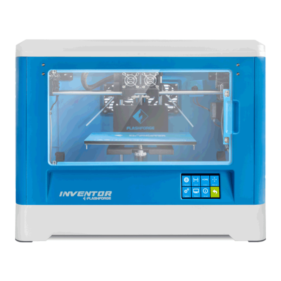
Chapter 2 . About Inventor 2.1 About Your Inventor 2.1.1 Main view: 1. Camera 2. Extruder fan Whole Machine 3. Timing belt 4. Vent 5. Build plate 6. Filament 7. Power input 8. Power switch 9. Touch screen 10. Reset button 11. - Page 12 Power Cord USB Cord Vent*2 Fan Baffle Cap Kit Box Build Sheet Quick State Guide Tweezers SD Card Leveling Sheet Screwdriver Scraper Screw Box Carving Knife Stamping Wrench Unclog Tool Hex wrench(1.5、2.0、2.5、3.0mm) Inventor User Guide | www.flashforge.com 0086‐ 0579‐82273989...
- Page 13 2.1.3 Terms The glass surface on which the Inventor builds an Build Plate object. The blue tape that covers Inventor’s build plate so that Build Tape the object can adhere to the build plate well. Build Volume The three dimensional amount of space that an object will use once it is completed.
- Page 14 Filament Diameter 1.75mm(±0.07) Nozzle Diameter 0.4mm Build Speed 30~200mm/s Software FlashPrint Support Formats 3MF/STL/OBJ/FPP/BMP/PNG/JPG/JPEG; GX/G Win xp/Vista/7/8/10、Mac OS、Linux 485*344*382(402)mm Prodcut Dimensions Net Weight 10.7Kg AC Input 100-240V~/4.5A-2.5A Connectivity USB cable, USB stick, WIFI Inventor User Guide | www.flashforge.com 0086‐ 0579‐82273989...
-
Page 15: Chapter 3. Unpacking
Make sure you read the whole unpacking guide) 1. (3-1)Put Inventor package on the clean, tidy workbench,using a knife to cut the tape ,then you can see two quick start guide,which will guide you know our Inventor 3D Printer. - Page 16 Box. 4.(3-4)The Inventor will have an accessory box on top of it, which will house the extruder set. Remove the box and the foam pad from the Inventor, and gently lay the extruder set on the Inventor build plate.
- Page 17 (3-6)Take out the PLA filament and ABS filament carefully which is under the build plate. (3-7)You’ve finished unpacking your Inventor. Next we will move on to the hardware assembly. 3‐7 Inventor User Guide | www.flashforge.com 0086‐ 0579‐82273989...
-
Page 18: Chapter 4 . Hardware Assembly
The Inventor comes pre-assembled and is almost ready-to-print (ARP). All you need to do is set the appropriate voltage, mount the extruder set, and install the filament. It will only take between 5 to 10 minutes before you can fire up the Inventor and prepare for your first 3D print! 4.1 Mounting the Extruder Set... -
Page 19: Installing Filament
M3x12 screw through the mounting hole of the extruder seat first. Afterwards, align the extruder set and tighten. 4.2 Installing Filament 4‐4 (4-4) Lock the filament in place by securing it with the filament spool holder and turning it counter-clockwise. Inventor User Guide | www.flashforge.com 0086‐ 0579‐82273989... -
Page 20: Plugging In Power Cord&Usb Cable
4.3 Plugging in Power Cord&USB Cable 4‐7 (4-7) Locate the power cord, and plug it into the Inventor. Optional: Locate the USB cord and plug one end into the Inventor and the other into Inventor User Guide | www.flashforge.com 0086‐ 0579‐82273989... -
Page 21: Loading And Unloading Filament
The Inventor supports USB . 4.4 Loading and Unloading Filament Filament must pass through the extruder and into the heating block in order to be melted. In this user guide, we will demonstrate loading and unloading filament using the left side extruder. - Page 22 (4-12) Filament will start to extrude out of the nozzle. Continue loading to ensure that the filament is extruding in a straight line. Refer to the troubleshooting section if the filament is extruding at an angle. Inventor User Guide | www.flashforge.com 0086‐ 0579‐82273989...
-
Page 23: Unloading Filament
Unloading filament: 4-13 (4-13) Remove the lid of the Inventor 4-14 (4-14) From the main menu, press the right icon labeled [ Tools (4-15) Select [ Filament ] [Unload Left 4-16 Inventor User Guide | www.flashforge.com 0086‐ 0579‐82273989... - Page 24 Inventor User Guide | www.flashforge.com 0086‐ 0579‐82273989...
- Page 25 (4-16)Wait for the extruder to heat up to the operating temperature. The extruder will alert you once it is at the operating temperature.(4-17) Unload the filament by gently guiding it out of the extruder. Inventor User Guide | www.flashforge.com 0086‐ 0579‐82273989...
-
Page 26: Chapter 5: Build Plate Leveling
The Inventor utilizes a three-point leveling system for its build plate. At the bottom of the build plate, there is one spring-loaded knob in the front and two in the back. - Page 27 Slide the paper back and forth again, and adjust the screw to create the same amount of friction as the previous step. Inventor User Guide | www.flashforge.com 0086‐ 0579‐82273989...
- Page 28 Slowly adjust all the screws by the same amount if there is no friction or too much friction. 7. (5-7)Press [ FINISH ] once you have finished this. Inventor User Guide | www.flashforge.com 0086‐ 0579‐82273989...
-
Page 29: Chapter 6: About Software
2. Start the software with the start menu shortcut or by clicking the software icon.(See 6-1) 6.2 Exploring FlashPrint 6. 2.1 Machine Type Selection ! After starting FlashPrint, you need to select the target machine type first. Inventor User Guide | www.flashforge.com 0086‐ 0579‐82273989... - Page 30 When you start FlashPrint, a dialog box will pop up. Just need to select Flashforge Inventor in the machine type list and click [OK]. You can also change the machine type via clicking [Print]--[Machine type]. Please see graphic 6-2: 6.2.2 Flashprint Menus Load one or multiple files.
- Page 31 Cut the model into several parts Print it directly with your Inventor or export to your USB stick. 6.2.3 Loading You can load a model file or Gcode file into your Flashprint by the following six methods: Method 1: Click the...
- Page 32 Bottom thickness: For tube, canister, lamp and stea to set up bottom thickness Top diameter: For tube, canister, lamp and stea to set up the top diameter Bottom diameter: For tube, canister, lamp and stea to set up the bottom diameter 6‐4 Plane 6-5 Inventor User Guide | www.flashforge.com 0086‐ 0579‐82273989...
- Page 33 Tube 6-6 Cansiter 6-7 Inventor User Guide | www.flashforge.com 0086‐ 0579‐82273989...
- Page 34 Lamp 6-8 Seal 6-9 6.2.4 Views ① Changing views Change model views by moving, rotating, scaling. ● Drag Click the [View] icon and then you can move the object by the following three methods: Inventor User Guide | www.flashforge.com 0086‐ 0579‐82273989...
- Page 35 [Reset]. ④ Show Model Outline Click [View]--[Show Model Outline], it will highlight the yellow border of the object Inventor User Guide | www.flashforge.com 0086‐ 0579‐82273989...
- Page 36 Click one ring and rotate on the present axis, you will see the rotation angle and direction in the center of circle. In this way, you could make the model rotate on X/Y/Z axis. Inventor User Guide | www.flashforge.com 0086‐ 0579‐82273989...
- Page 37 6.2.8 Left-click on the model to select it and double-click on the Cut icon to set the cut plane. The direction and position are available for setting. ①Draw with Mouse Inventor User Guide | www.flashforge.com 0086‐ 0579‐82273989...
- Page 38 ②X Plane ③Y Plane ④Z Plane 6.2.9 Extruder (6-10) Choose L/R extruder to print, pitch on the model,click on two times, now you can set extruder . Inventor User Guide | www.flashforge.com 0086‐ 0579‐82273989...
- Page 39 “treelike”and “linear”, when choose “treelike”, click [OK], then the support generated will be treelike structure; when choose “linear”, click [OK], then the support generated will be linear structure; if the model already had support, when you choose Inventor User Guide | www.flashforge.com 0086‐ 0579‐82273989...
- Page 40 ).Loosen the left mouse button, if support column doesn’t meet with model, then support will be generated on origin and terminal point(the highlighted preview support won’t generate support structure ) Inventor User Guide | www.flashforge.com 0086‐ 0579‐82273989...
- Page 41 6.2.11 Print 6‐13 ① Preview: Choose to enter preview interface or not ② Print when slice done: Print or not when slice done Inventor User Guide | www.flashforge.com 0086‐ 0579‐82273989...
- Page 42 ● Primeter Shells: Maximize is 10 a. Top Solid Layer: Maximize is 10, minimum is 1. b. Bottom Solid Layer: Maximize is 10, minimum is 1. ● Infill Inventor User Guide | www.flashforge.com 0086‐ 0579‐82273989...
- Page 43 ● Others Pause At Heights: Allows users to pre-set a height in which the print will suspend automatically. The function usually applied when you want to change the Inventor User Guide | www.flashforge.com 0086‐ 0579‐82273989...
- Page 44 ”.fpp” in this type of file,all models in the scene (include support) are independent .after reloading the files, extruder configuration information and model position will be as same as the configuration during saving. Method 2: Inventor User Guide | www.flashforge.com 0086‐ 0579‐82273989...
- Page 45 6.2.13 Edit Menus Undo ① Allows users to undo the recent edits by the following two methods: Method 1: Click [Edit]--[Undo]. Method 2: Press the shortcut Ctrl+Z. ② Redo Inventor User Guide | www.flashforge.com 0086‐ 0579‐82273989...
- Page 46 Method 2: Press the shortcut Delete ⑦ Surface to Platform After selecting the model, you can make the model surface to platform via the following operation. Click [Edit]--[Surface to Platform] into surface to platform mode(6-18) Inventor User Guide | www.flashforge.com 0086‐ 0579‐82273989...
- Page 47 6.2.14 Print Menus ① Connect Machine You can connect the Inventor with your PC via a USB cable or WIFI. Note: The machine icon on the bottom right displays the connection status: Connected Disconnected Method 1:Connect Via USB Cable...
- Page 48 6-19 Method 2: Connect Via WIFI 1. Turn on Inventor. Make sure the build plate is leveled and filament is loaded on the left extruder. Turn on Wi-Fi on the Inventor. To do this, press...
- Page 49 ], select a working network, enter the corresponding password and save. 6-22 7. Restart the interface, close the page, turn off the Inventor, disconnect from the network, and wait for 10 seconds. 8. Turn the Inventor back on and connect to the Inventor network. In FlashPrint,...
- Page 50 10. If successfully connected, you will see the following red mark. ① Connect Inventor with your PC under STA mode a. Turn on the WIFI of Inventor and connect your PC with Inventor via the WIFI. ② Disconnect Inventor Click [Print]--[Disconnect] to disconnect your PC and Inventor.
- Page 51 X/Y Speed and Z Speed: Set the move speed of extruder/ build platform. ● Limit Switch: In order to protect your Inventor, three limit switches are equipped to control the maximum position, and the three limit switches corresponding to X/Y/Z axis limit switch.
- Page 52 Step 2: Choose corresponding printer type and firmware version and click [OK] the firmware updating box. After confirming the printer is in free state, the software will automatically update the firmware. Inventor User Guide | www.flashforge.com 0086‐ 0579‐82273989...
- Page 53 6-23 Step 3:Reboot you Inventor and wait for 4-5 seconds, then you can see the update process bar. When the update finishes, it will go back to the main interface. Step 4:Tap[Tools]--[About] to check] to check whether the updated version is right.
-
Page 54: Chapter 7: Printing
There are three connection methods in order to print using the Inventor. All methods, which include USB, SD card, and Wi-Fi are covered in this chapter. - Page 55 6. Now the 3D model is ready to be created. Before introducing the connection methods, let me give you a brief introduction of Inventor’s interfaces. Print Read the print file from The local memory card The SD card Return arrow Inventor User Guide | www.flashforge.com 0086‐ 0579‐82273989...
- Page 56 Tools in print interface Filament: To change filament during printing. (Note: You need to suspend the operation first) Wifi: To turn on the Wifi Cancel: To end the tool orders and return to the print interface. Inventor User Guide | www.flashforge.com 0086‐ 0579‐82273989...
- Page 57 Tap [Yes] to save the setting while tap [No] to cancel the setting. The picture displays the preheat interface. It shows the actual temperature and the target temperature. Tap the [Stop] button to abort the preheat job. Inventor User Guide | www.flashforge.com 0086‐ 0579‐82273989...
- Page 58 Tap [Setting] to enter the setting interface Language: To set the display language TP Adjust: Adjust the touch screen Factory Reset: Restore factory defaults Fan on: To turn on/off the fan WIFI: To turn on/off the Wifi Inventor User Guide | www.flashforge.com 0086‐ 0579‐82273989...
- Page 59 To tap the “+” on the touch screen to adjust the touch screen. WIFI: Turn on the WIFI: Turn on the wifi, release the wifi hotspot and set the wifi on computer Return arrow Inventor User Guide | www.flashforge.com 0086‐ 0579‐82273989...
-
Page 60: Methods Of Printing
7.2 Methods of printing Printing from USB 1. Connect Inventor to the computer using the included USB 2.0 cable. 2. Turn on the Inventor. Make sure the build plate is leveled and filament is loaded to the left extruder. 3. Select... - Page 61 After the object is done slicing, take the SD card from the computer. Insert it into the SD card slot on the Inventor. 6. Turn on the Inventor. Make sure the build plate is leveled and filament is loaded on the left extruder.
- Page 62 2. Turn on Wi-Fi on the Inventor. To do this, press [ Tools [ Setting [ WIFI [ WIFI ON]. 3.A connection called“HF-LPB” can be found on the list of available networks. Connect to this network. 4. Open your Internet browser. Type in “10.10.100.254” and hit...
- Page 63 Port” as shown on printer LCD screen. Then, click [ Connect 8. Now the Inventor is connected with FlashPrint. A status box at the lower right corner will show the temperature of both extruders and the Platform. 9. In FlashPrint, click [ Print ].
- Page 64 “Supports” the left or right extruder.Click [ OK ] to begin slicing. Inventor User Guide | www.flashforge.com 0086‐ 0579‐82273989...
-
Page 65: Chapter 8: Advanced Printing
Chapter 8: Advanced Printing When you get familiar with your Inventor, you will definitely want to accomplish some advanced prints. This chapter will take you to get to know the advanced printing skills. Expert Mode grants the users more freedom of parameter edition. There are two modes are available for users, one is “Basic Mode”... - Page 66 Retraction Length: Amount of retraction. Retraction can help users reduce stringing or oozing during printing. (The default value shall be suggested.) b. Speed: Speed at which the filament is retracted. The default value shall be suggested. Inventor User Guide | www.flashforge.com 0086‐ 0579‐82273989...
- Page 67 Mode: There are two options for Start Point mode. One is “closest to specific location”, the other is “use random start points”. b. X: The coordinate value of X c. Y: The coordinate value of Y Inventor User Guide | www.flashforge.com 0086‐ 0579‐82273989...
- Page 68 . Solid Speed: Speed at which the top/bottom parts are printed. b. Sparse Speed: Speed at which the infill is printed. 3)Combine Infill a. Maximum Combine Layers: Select the layer amount according to the layer height. Inventor User Guide | www.flashforge.com 0086‐ 0579‐82273989...
- Page 69 Select extruder: Choose lfte or right extruder to print you model. 2)Treelike a. Speed: Speed at which the treelike supports are printed. b. Space to Model(X/Y): The gap between the treelike supports and the model contact surface (in the X/Y directions). Inventor User Guide | www.flashforge.com 0086‐ 0579‐82273989...
- Page 70 Margin: The distance between raft’s outline and outline of model’s first layer. If the raft is enabled, the extra raft area around the object is also enabled. Increasing the margin will create a stranger raft while using more matrial and leaving less area for your object. Inventor User Guide | www.flashforge.com 0086‐ 0579‐82273989...
- Page 71 Shell Count: To control the printing laps for support shell. c. Space to Model: The minimum distance between the wall and model. d. Speed: Speed at which the wall is printer. 8‐6 Advanced 1)Stepper Motor Voltage(Usually keep default) Inventor User Guide | www.flashforge.com 0086‐ 0579‐82273989...
- Page 72 Path Width: The width of the path, the default value is 0.4mm. Keeping default is suggested. c. Path Resolution: The default value is 0.1mm. The bigger the value is, the lower the extrusion resolution is. On the contrary, the extrusion resolution is much higher. Inventor User Guide | www.flashforge.com 0086‐ 0579‐82273989...
-
Page 73: Skills On Supports
Video:Skills on Supports) Support structures enable the printing of models with steep overhangs and cantilevered sections. The Inventor 3D printer utilizes Fused Filament Fabrication (FFF) technology, which works on the additive manufacturing principle of heating Inventor User Guide | www.flashforge.com... - Page 74 Features:Full coverage of supports improves the model stability. But the supports on the surface are difficult to be removed and will definitely reduce the print quality. Treelike Support Structure:Suitable for models with small area overhang(s).(You are suggested printing a raft) Inventor User Guide | www.flashforge.com 0086‐ 0579‐82273989...
- Page 75 Features:Treelike support structure is proprietary to Flashforge Corporation. And this structure can save support material and can be easily removed. However, compared with the linear support structure, it’s of less stability. So you are suggested to manually add more supports after auto-generating treelike supports.
- Page 76 Wrong:Linear support structure 2) Model with Small-area Overhang Inventor User Guide | www.flashforge.com 0086‐ 0579‐82273989...
- Page 77 Right:Treelike support structure Wrong:Linear support structure Manual Modification Inventor User Guide | www.flashforge.com 0086‐ 0579‐82273989...
- Page 78 For the experienced 3D printer users, the [Add] and [Delete] buttons are suggested using for manually adding or deleting supports. 1)Manual Add 8-10 You can add the support structure manually to according to the actual shape of the model. Inventor User Guide | www.flashforge.com 0086‐ 0579‐82273989...
- Page 79 Left click [Add] on the left, and then click on the position when support structure is needed. Press down the left mouse button and drag to generate the support. 2)Manual Delete 8-11 Like the picture above, a hole inside the model doesn’t need any supports. Inventor User Guide | www.flashforge.com 0086‐ 0579‐82273989...
-
Page 80: Control Over Printing Quality
Such as the models below, you need to put one of the surfaces onto the platform.(Please refer to 5.1.12-⑦Surface to Platform) ① Improper Proper 8‐12 Inventor User Guide | www.flashforge.com 0086‐ 0579‐82273989... - Page 81 Look at the model below: Picture 8-15 is the preview of the model’s original placement and Picture 8-16 is the preview of the model with support structure. Inventor User Guide | www.flashforge.com 0086‐ 0579‐82273989...
- Page 82 (8-17) Looking at the Picture 8-16, we will definitely find that the complex supports will influence the smoothness of the model. By analyzing the model’s feature, cutting from the Y plane will be suitable. Inventor User Guide | www.flashforge.com 0086‐ 0579‐82273989...
- Page 83 8-17 (8-18) The model preview after cutting. 8-18 (8-19) Click [Edit]--[Surface to Platform] to put the flat surfaces onto the platform. Inventor User Guide | www.flashforge.com 0086‐ 0579‐82273989...
- Page 84 7-10 Comparison Inventor User Guide | www.flashforge.com 0086‐ 0579‐82273989...
-
Page 85: Chapter 9: Supports And Service
Flashforge team standby and ready to help you overcome any challenges you may have with your Inventor. If the issues or questions are not covered in this User Guide, you can seek for solutions on our office website or contact us via telephone.
Need help?
Do you have a question about the Inventor and is the answer not in the manual?
Questions and answers