ABB IRC5 Product Manual
Panel mounted controller
Hide thumbs
Also See for IRC5:
- Operating manual (590 pages) ,
- Product manual (550 pages) ,
- Applications manual (110 pages)
Table of Contents
Advertisement
Quick Links
Advertisement
Table of Contents

Related Manuals for ABB IRC5


Summary of Contents for ABB IRC5
- Page 1 Product manual Panel Mounted Controller IRC5 RobotWare 5.0...
- Page 3 Product manual IRC5 Panel Mounted Controller M2004 Document ID: 3HAC027707-001 Revision: D...
- Page 4 Except as may be expressly stated anywhere in this manual, nothing herein shall be construed as any kind of guarantee or warranty by ABB for losses, damages to persons or property, fitness for a specific purpose or the like.
-
Page 5: Table Of Contents
2.5.4 Connecting fan unit to IRC5 Panel Mounted Drive Module ......59... - Page 6 2.9.3 Installation of external operator's panel, IRC5........91 2.9.4 Installation of I/O, Gateways and encoder interface units, IRC5 ......94 3 Maintenance activities, controller IRC5 3.1 Maintenance schedule, controller IRC5 .
- Page 7 Table of Contents 6.2 Manipulator cables ..............188 6.2.1 Manipulator variants.
- Page 8 Table of Contents 3HAC027707-001 Revision: D...
-
Page 9: Overview
• repair personnel. Prerequisites A maintenance/repair/ installation craftsman working with an ABB Robot must: • be trained by ABB and have the required knowledge of mechanical and electrical installation/repair/maintenance work. References Reference Document ID Emergency safety information 3HAC027098-001... - Page 10 • Manipulator cables Changes made in section Maintenance schedule, controller IRC5. Replacement of fans every third year is withdrawn and inspection interval is changed from once a year to twice a year. Minor corrections made. New option PROFINET Fieldbus Adapter is added to section Replacement of fieldbus adapter in the computer unit DSQC 639.
-
Page 11: Product Documentation, M2004
This means that any given delivery of robot products will not contain all documents listed, only the ones pertaining to the equipment delivered. However, all documents listed may be ordered from ABB. The documents listed are valid for M2004 robot systems. - Page 12 This group of manuals is aimed at those having first hand operational contact with the robot, that is production cell operators, programmers and trouble shooters. The group of manuals includes: • Emergency safety information • General safety information • Getting started, IRC5 • IRC5 with FlexPendant • RobotStudio • Introduction to RAPID •...
-
Page 13: Safety
1 Safety 1.1. Introduction 1 Safety 1.1. Introduction Overview The safety information in this manual is divided in two categories: • general safety aspects, important to attend to before performing any service or installation work on the controller. These are applicable for all service work and are found in section General safety information. -
Page 14: General Safety Information
1 Safety 1.2.1. Introduction 1.2 General safety information 1.2.1. Introduction Definitions This section details general safety information for personnel performing installation, repair and maintenance work. Sections The general safety information is divided into the following sections. Contents Containing 1. General information •... -
Page 15: General Information
Limitation of liability Any information given in this manual regarding safety, must not be construed as a warranty by ABB that the industrial robot will not cause injury or damage even if all safety instructions are complied with. Related information... -
Page 16: Safety Risks
The mains supply to the robot must be connected in such a way that it can be turned off outside the robot’s working space. Voltage related risks, IRC5 controller A danger of high voltage is associated with, for example, the following parts: •... -
Page 17: Safety Actions
1 Safety 1.2.4.1. Fire extinguishing 1.2.4. Safety actions 1.2.4.1. Fire extinguishing NOTE! Use a CARBON DIOXIDE (CO ) extinguisher in the event of a fire in the robot system (robot or controller)! 3HAC027707-001 Revision: D... -
Page 18: Safety Stops
1 Safety 1.2.5.1. Overview of robot stopping functions 1.2.5. Safety stops 1.2.5.1. Overview of robot stopping functions Overview Stops are categorized/classified by standards IEC 60204-1:2005 and ISO 10218-1:2006. There are several different robot stopping functions in the robot system. • Hardware stops connected to the run chain. - Page 19 1 Safety 1.2.5.1. Overview of robot stopping functions Continued Stop connections: Description: General stop Disconnects drive power in all operating modes. To be used as "Protective stop" in all operating modes. Also called "Safety stop". Superior stop Disconnects drive power in all operating modes. To be used as "Protective stop"...
- Page 20 1 Safety 1.2.5.1. Overview of robot stopping functions Continued Stop with system input signals In addition to the hardware stops as described above, it is also possible to define system input signals, which will give an immediate or delayed stop of different modes for all tasks and robots, when activated.
- Page 21 1 Safety 1.2.5.1. Overview of robot stopping functions Continued Instruction: Description: Arguments: Stop The current move instruction will \NoRegain - the robot will not be finished before the robot stops. return to the stop point when A restart will continue the program restarted, e.g.
- Page 22 1 Safety 1.2.5.1. Overview of robot stopping functions Continued System failure stops Type of stop: Description: SysFail At system failure raising a SysFail error the robot will stop imme- diately, with brakes being activated. This is an uncontrolled stop category 0. Power fail At power failure the robot will stop immediately, with brakes being activated.
-
Page 23: What Is An Emergency Stop
1 Safety 1.2.5.2. What is an emergency stop? 1.2.5.2. What is an emergency stop? Definition of emergency stop An emergency stop is a state that overrides any other robot control, disconnects drive power from the robot motors, stops all moving parts, and disconnects power from any potentially dangerous functions controlled by the robot system. -
Page 24: What Is A Safety Stop
1 Type of safety stops Safety stops are activated through special signal inputs to the controller, see Product manual - IRC5. The inputs are intended for safety devices such as cell doors, light curtains, or light beams. Safety stop: Description: Automatic mode stop (AS) Disconnects drive power in automatic mode. -
Page 25: What Is Safeguarding
1 Safety 1.2.5.4. What is safeguarding? 1.2.5.4. What is safeguarding? Definition Safeguarding are safety measures consisting of the use of safeguards to protect persons from hazards which cannot reasonably be removed or sufficiently eliminated by design. A safeguard prevents hazardous situations by stopping the robot in a controlled manner when a certain safeguarding mechanism such as a light curtain is activated. -
Page 26: Safety Related Instructions
1 Safety 1.3.1. Safety signals, general 1.3 Safety related instructions 1.3.1. Safety signals, general General This section specifies all dangers that may arise from performing the work detailed in the manual. Each danger is detailed in its own section consisting of: •... - Page 27 1 Safety 1.3.1. Safety signals, general Continued Symbol Designation Signification ELECTROSTATIC The electrostatic discharge (ESD) symbol indicates DISCHARGE (ESD) electrostatic hazards which could result in severe damage to the product. Electrostatic discharge (ESD) NOTE Note symbols alert you to important facts and conditions.
-
Page 28: Danger - Make Sure That The Main Power Has Been Switched Off
1 Safety 1.3.2. DANGER - Make sure that the main power has been switched off! 1.3.2. DANGER - Make sure that the main power has been switched off! Description Working with high voltage is potentially lethal. Persons subjected to high voltage may suffer cardiac arrest, burn injuries, or other severe injuries. -
Page 29: Warning - The Unit Is Sensitive To Esd
1 Safety 1.3.3. WARNING - The unit is sensitive to ESD! 1.3.3. WARNING - The unit is sensitive to ESD! Description ESD (electrostatic discharge) is the transfer of electrical static charge between two bodies at different potentials, either through direct contact or through an induced electrical field. When handling parts or their containers, personnel not grounded may potentially transfer high static charges. -
Page 30: Controller
1 Safety 1.3.4. CAUTION - Make sure that there are no loose screws or turnings inside the IRC5Panel Mounted Controller 1.3.4. CAUTION - Make sure that there are no loose screws or turnings inside the IRC5Panel Mounted Controller Description To avoid damaging the product, do not proceed working before checking that there are no loose screws, turnings or other parts inside the Control ModuleorDrive Module after that work has been performed inside the cabinet. -
Page 31: Caution - Hot Components In Controller
1 Safety 1.3.5. CAUTION - Hot components in controller 1.3.5. CAUTION - Hot components in controller Description Units and heat sinks are HOT after running the robot! Touching the units and heat sinks may result in burns! With higher environment temperature more surfaces on the controller get HOT and may result in burns. - Page 32 1 Safety 1.3.5. CAUTION - Hot components in controller 3HAC027707-001 Revision: D...
-
Page 33: Installation And Commissioning, Irc5
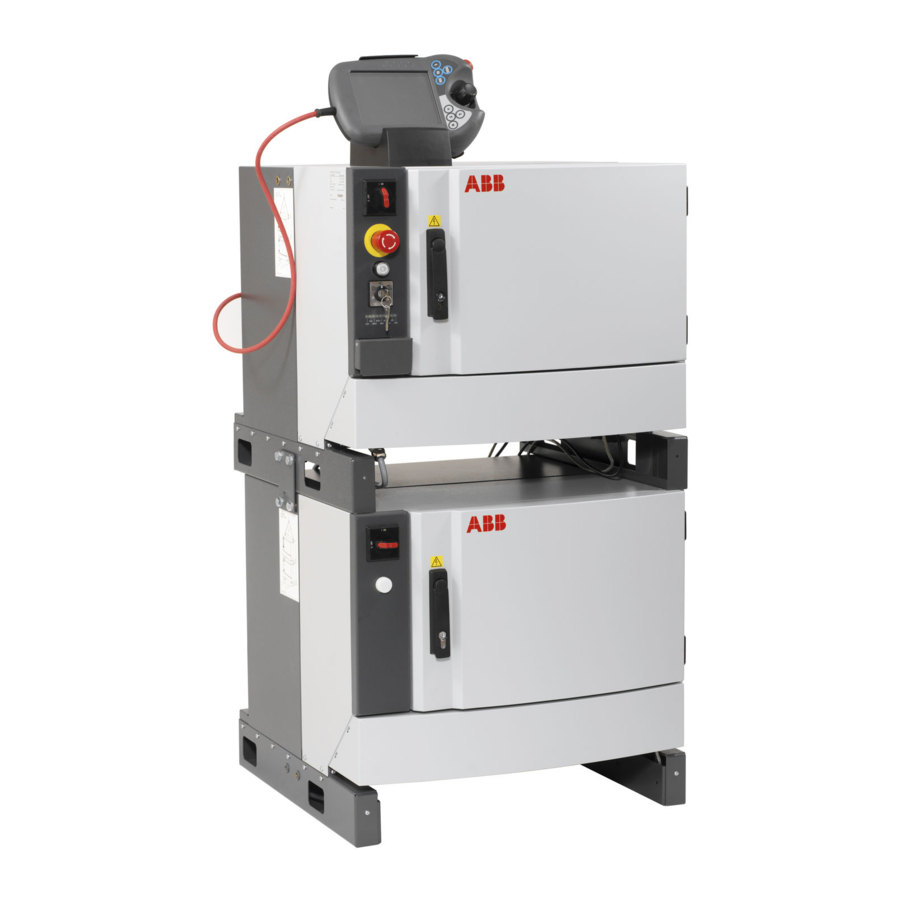
2 Installation and Commissioning, IRC5 2.1. Overview 2 Installation and Commissioning, IRC5 2.1. Overview General The IRC5 Panel Mounted Controller is made up of the following modules: • Control Module • Drive Module xx0600003313 Control Module Drive Module Fan unit... - Page 34 This is particularly important for the safety equipment to maintain the safety integrety of the installation. Equipment Following parts can be delivered with the IRC5 Panel Mounted Controller: Part. no. Description Note...
-
Page 35: Installation Activities
Controller. controller is detailed in section Unpacking, IRC5 Panel MountedController on page 34 2. Install the IRC5 Panel Mounted Controller. How to install the IRC5 controller is detailed in sectionInstallation, IRC5 Panel Mounted Controller on page 36 3. Connect the manipulator to IRC5 Panel How to connect the manipulator to IRC5 MountedController. -
Page 36: Transporting And Handling
When unpacking the controller, check that it was not damaged during transport. NOTE! If the IRC5 Panel MountedController is going to be stored before unpacking and installation, read the following information regarding storage conditions. Storage conditions... - Page 37 2 Installation and Commissioning, IRC5 2.3.1. Unpacking, IRC5 Panel MountedController Continued Protection class The table below shows the protection classes for the IRC5 Panel MountedController and FlexPendant: Equipment Protection class IRC5 Panel Mounted Controller IP20 FlexPendant IP54 3HAC027707-001 Revision: D...
-
Page 38: On-Site Installation
2 Installation and Commissioning, IRC5 2.4.1. Installation, IRC5 Panel Mounted Controller 2.4 On-site Installation 2.4.1. Installation, IRC5 Panel Mounted Controller Dimensions The illustration below shows the required installation space for the IRC5 Panel Mounted Controller. xx0600003314 Continues on next page 3HAC027707-001 Revision: D... - Page 39 2 Installation and Commissioning, IRC5 2.4.1. Installation, IRC5 Panel Mounted Controller Continued xx0700000031 Installation conditions xx0600003450 Continues on next page 3HAC027707-001 Revision: D...
- Page 40 NOTE! The Control Module and Drive Module must be mounted and connected to the same earth. Procedure The following procedure details how to install the IRC5 Panel Mounted modules. Action Note/Illustration 1. Fit the module on pre-mounted M5 screws (4 pcs).
-
Page 41: Connections
2.5.1. Connecting the manipulator cables to the IRC5 Panel Mounted Drive Module 2.5 Connections 2.5.1. Connecting the manipulator cables to the IRC5 Panel Mounted Drive Module General The following section details how to connect the manipulator cables to the IRC5 Panel Mounted Drive Module. Location xx0600003271... - Page 42 2 Installation and Commissioning, IRC5 2.5.1. Connecting the manipulator cables to the IRC5 Panel Mounted Drive Module Continued Prepare the power and signal cable If the power and signal cables are not as open end cables they need to be prepared.
- Page 43 2 Installation and Commissioning, IRC5 2.5.1. Connecting the manipulator cables to the IRC5 Panel Mounted Drive Module Continued Connecting the power cable The following procedure details how to connect the manipulator power cable to the IRC5 Panel Mounted Drive Module. Action Note/Illustration 1.
- Page 44 2 Installation and Commissioning, IRC5 2.5.1. Connecting the manipulator cables to the IRC5 Panel Mounted Drive Module Continued Action Note/Illustration 3. Connect the power cable to the connection block XT1 and Contactor interface board connector A43:XS21 and Drive Module earth point.
- Page 45 2 Installation and Commissioning, IRC5 2.5.1. Connecting the manipulator cables to the IRC5 Panel Mounted Drive Module Continued Connecting the signal cable The following procedure details how to connect the manipulator signal cable to the IRC5 Panel Mounted Drive Module. Action Note/Illustration 1.
- Page 46 2 Installation and Commissioning, IRC5 2.5.1. Connecting the manipulator cables to the IRC5 Panel Mounted Drive Module Continued Action Note/Illustration 6. Route the signal cable as the illustration to the right shows and fasten it with cable straps. xx0600003289 7. Connect the signal cable shield.
- Page 47 2 Installation and Commissioning, IRC5 2.5.1. Connecting the manipulator cables to the IRC5 Panel Mounted Drive Module Continued Connection table IRB 140 Power cable: Wire no. Specification Connection point 30XAWG16 2XAWG10 BK/WH XT1:1 XT1:2 BU/BK XT1:3 BN/WH XT1:4 BN/RD XT1:5...
- Page 48 2 Installation and Commissioning, IRC5 2.5.1. Connecting the manipulator cables to the IRC5 Panel Mounted Drive Module Continued Wire no. Specification Connection point Pair2 WH A42.X4:4 Pair2 OG A42.X4:5 Pair3 WH A42.X4:6 Pair3 GN A42.X4:7 Pair4 WH A42.X4:6 Pair4 BN A42.X4:7...
- Page 49 2 Installation and Commissioning, IRC5 2.5.1. Connecting the manipulator cables to the IRC5 Panel Mounted Drive Module Continued Wire no. Specification Connection point XT1:6 BK/WH XT1:7 XT1:8 BU/BK XT1:9 BK/RD XT1:10 BK/GN XT1:11 BK/BU XT1:12 XT1:13 BN/GN XT1:14 BN/RD XT1:15...
- Page 50 2 Installation and Commissioning, IRC5 2.5.1. Connecting the manipulator cables to the IRC5 Panel Mounted Drive Module Continued Wire no. Specification Connection point XT5 (CPJ) XT5 (CPK) XT5 (CPL) XT5 (CPM) Conductor to cut off Conductor to cut off Shield XT5 (0V Earth) Wire no.
- Page 51 2 Installation and Commissioning, IRC5 2.5.1. Connecting the manipulator cables to the IRC5 Panel Mounted Drive Module Continued External customer signal cable: Wire no. Specification Connection point Pair 1 WH XT5 (CSA) Pair 1 BU XT5 (CSB) Pair 2 WH...
- Page 52 2 Installation and Commissioning, IRC5 2.5.1. Connecting the manipulator cables to the IRC5 Panel Mounted Drive Module Continued Wire no. Specification Connection point GY/BK XT1:20 GY/BU XT1:21 OG/WH XT1:22 OG/BU XT1:23 OG/BK XT1:24 OG/RD XT1:25 GY/GN XT1:26 OG/GN A43:XS21 GY/WH...
- Page 53 2 Installation and Commissioning, IRC5 2.5.1. Connecting the manipulator cables to the IRC5 Panel Mounted Drive Module Continued Customer cable: Wire no. Specification Connection point XT5 (CPA) XT5 (CPB) XT5 (CPC) XT5 (CPD) XT5 (CPE) XT5 (CPF) XT5 (CPJ) XT5 (CPK)
- Page 54 2 Installation and Commissioning, IRC5 2.5.1. Connecting the manipulator cables to the IRC5 Panel Mounted Drive Module Continued Wire no. Specification Connection point Pair 14 BK Conductor to cut off Pair 14 BN Conductor to cut off Pair 15 BK...
-
Page 55: Connecting Power Supply To The Irc5 Panel Mounted Controller
2 Installation and Commissioning, IRC5 2.5.2. Connecting power supply to the IRC5 Panel Mounted Controller 2.5.2. Connecting power supply to the IRC5 Panel Mounted Controller General The following section details how to connect power supply to the IRC5 Panel Mounted Controller. Location xx0600003295... - Page 56 2 Installation and Commissioning, IRC5 2.5.2. Connecting power supply to the IRC5 Panel Mounted Controller Continued Required equipment Equipment Note Incoming power cable Line filter Miscellaneous parts on page 186. Standard toolkit The contents are defined in section Standard Toolkit...
- Page 57 2 Installation and Commissioning, IRC5 2.5.2. Connecting power supply to the IRC5 Panel Mounted Controller Continued Connecting power supply 230V 10A to Drive Module The following procedure details how to connect power supply to the Drive Module. Action Note/Illustration 1. Route the power supply 230V 10A cable as shown in the illustration to the right.
- Page 58 2 Installation and Commissioning, IRC5 2.5.2. Connecting power supply to the IRC5 Panel Mounted Controller Continued Connecting power supply 230V 10A to Control Module The following procedure details how to connect power supply to the Control Module. Action Note/Illustration 1. Route and strap the power supply 230V 10A cable as the illustration to the right shows.
- Page 59 2 Installation and Commissioning, IRC5 2.5.3. Connecting communication cables between IRC5 Panel Mounted Drive Module and Control Module 2.5.3. Connecting communication cables between IRC5 Panel Mounted Drive Module and Control Module General The following section details how to connect the communication cables between the IRC5 Panel Mounted Drive Module and Control Module.
- Page 60 2 Installation and Commissioning, IRC5 2.5.3. Connecting communication cables between IRC5 Panel Mounted Drive Module and Control Module Continued Required equipment Equipment Art. no. Note Ethernet cable 3HAC026292-001 Panel board/Contactor interface 3HAC024201-001 board cable Standard toolkit Described in section Standard toolkit.
-
Page 61: Connecting Fan Unit To Irc5 Panel Mounted Drive Module
2.5.4. Connecting fan unit to IRC5 Panel Mounted Drive Module 2.5.4. Connecting fan unit to IRC5 Panel Mounted Drive Module General The following section details how to connect the fan unit to the IRC5 Panel Mounted Drive Module. Location xx0600003323... - Page 62 2 Installation and Commissioning, IRC5 2.5.4. Connecting fan unit to IRC5 Panel Mounted Drive Module Continued Connecting fan unit to Drive Module The following procedure details how to connect the fan unit to the Drive Module. Action Note/Illustration 1. Connect fan unit to Drive Module E1.XP1...
-
Page 63: Connecting A Flexpendant
2 Installation and Commissioning, IRC5 2.5.5. Connecting a FlexPendant 2.5.5. Connecting a FlexPendant Location of FlexPendant connector The FlexPendant connector is located as shown below. xx0600003219 FlexPendant connector Connecting a FlexPendant Action Info 1. Locate the FlexPendant socket connector The controller must be in manual mode. -
Page 64: Connecting A Pc To The Service Port
2 Installation and Commissioning, IRC5 2.5.6. Connecting a PC to the service port 2.5.6. Connecting a PC to the service port NOTE! The service port shall only be used for direct connection to a PC as described in this procedure. It must not be connected to a LAN (local area network), since it has a DHCP server that automatically distributes IP addresses to all units connected to the LAN. - Page 65 2 Installation and Commissioning, IRC5 2.5.6. Connecting a PC to the service port Continued Total max. number of applications using robapi running on the same pc connected to one controller has no builtin maximum, however UAS limits the max number of logged on user’s to 50.
- Page 66 2 Installation and Commissioning, IRC5 2.5.6. Connecting a PC to the service port Continued Action Illustration 2. Use the delivered category 5 Ethernet The cable is delivered in the RobotWare crossover boot cable with RJ45 product box. connectors. 3. Connect the boot cable to the network port of your PC.
-
Page 67: Connection To Serial Channel Connector
2 Installation and Commissioning, IRC5 2.5.7. Connection to serial channel connector 2.5.7. Connection to serial channel connector Overview The controller has one serial channel RS232 for permanent use which can be used for communication point to point with printers, terminals, computers or other equipment. -
Page 68: The Motors On/Motors Off Circuit
2 Installation and Commissioning, IRC5 2.5.8. The MOTORS ON/MOTORS OFF circuit 2.5.8. The MOTORS ON/MOTORS OFF circuit Outline diagram The MOTORS ON/MOTORS OFF circuit is made up of two identical chains of switches. The diagram shows the available customer connections, AS, GS, SS and ES. - Page 69 2 Installation and Commissioning, IRC5 2.5.8. The MOTORS ON/MOTORS OFF circuit Continued Function of the MOTORS ON/MOTORS OFF circuit The circuit monitors all safety related equipment and switches. If any of the switches is opened, the MOTORS ON/MOTORS OFF circuit switches the power to the motors off.
- Page 70 2 Installation and Commissioning, IRC5 2.5.8. The MOTORS ON/MOTORS OFF circuit Continued Technical data per chain GS/AS/SS open "0" < 5 V External supply of GS/AS/SS Max. + 35 VDC Min. - 35 VDC GS/AS/SS Filter time 2,0 ms Max. potential in relation to the...
- Page 71 2 Installation and Commissioning, IRC5 2.5.8. The MOTORS ON/MOTORS OFF circuit Continued Connection of ES1/ES2 on panel unit The diagram below shows the terminals for the emergency circuits. The supply from internal 24V (X1/X2:10) and 0V (X1/X2:10) is displayed. For an ext.
- Page 72 2 Installation and Commissioning, IRC5 2.5.8. The MOTORS ON/MOTORS OFF circuit Continued Technical data ES1 and ES2 max output voltage 120 VAC or 48 VDC ES1 and ES2 max output current 120 VAC: 4 A 48 VDC L/R: 50 mA...
-
Page 73: Connection Of External Safety Relay
2 Installation and Commissioning, IRC5 2.5.9. Connection of external safety relay 2.5.9. Connection of external safety relay Description The motor contactors K42 and K43 in the IRC5Panel Mounted Drive Module can operate with external equipment if external relays are used. -
Page 74: Connection Of Drive Module Disconnect, By Limit Switch
The table below details the required equipment. Equipment Note Wire AWG20 Switch 24V 0,5A Operating manual - RobotStudio Operating manual - IRC5 with FlexPendant Standard toolkit Circuit diagram Circuit Diagram on page 195 Continues on next page 3HAC027707-001 Revision: D... - Page 75 The following procedures details how to enabeling the system for a Drive Module Disconnect. Action 1. On the FlexPendant, Tap ABB and then Tap Control Panel. 2. In the Control panel menu, Tap Configuration. 3. In the Configuration menu, Tap Topics, and select Motion.
- Page 76 2 Installation and Commissioning, IRC5 2.5.10. Connection of Drive Module Disconnect, by limit switch Continued Action Note/illustration 2. Reconnect the X22 connector. xx0600003250 3. Move the program pointer to main in the RAPID-program where the disconnected mechanical units are active.
-
Page 77: Connecting A Limit Switch Override Push Button
The following procedure details how to connect a Limit switch override circuit in a Panel Mounted Controller. Action Note/illustration Danger DANGER! Before any work inside the IRC5 controller modules, please observe the safety information in section DANGER - Make sure that the main power has been switched off! on page... - Page 78 2 Installation and Commissioning, IRC5 2.5.11. Connecting a Limit switch override push button Continued Action Note/illustration 2. Attach two additional contact blocks on the existing push button (Motors on). xx0500002553 • A: Additional contact blocks • B: Existing contact, lamp blocks •...
-
Page 79: Drive System
2.6 Drive system 2.6.1. Drive functions, general General The manipulator is powered by power electronics found in the IRC5 controller. Standard configurations The drive system (drive units and rectifier) is available in two sizes depending on which robot to drive and other power requirements. -
Page 80: Configuration Of The Drive System, Irc5
2.6.2. Configuration of the drive system, IRC5 General The IRC5 Panel Mounted Controller contains a number of drive units, rectifiers and filters. Any allowed combination of these, depending on the robot type, is specified below. The robot system may also be equipped with up to three additional drive modules, which are described in the Product manual - IRC5, section Installation of additional drive module. - Page 81 2 Installation and Commissioning, IRC5 2.6.2. Configuration of the drive system, IRC5 Continued IRB 140 The figure below shows the drive unit positions. The table specifies which units may be fitted in which positions. xx0600003245 Pos. Identification Description Art. no.
- Page 82 2 Installation and Commissioning, IRC5 2.6.2. Configuration of the drive system, IRC5 Continued IRB 1600, 260, 2400 The figure below shows the drive unit. The table specifies which units may be fitted in which positions. xx0600003245 Pos. Identification Description Art. no.
-
Page 83: Memory Functions
Compact flash memory 256MB containing ABB VxWorks boot image software. • 256 MB DDR SDRAM memory (Synchronous Dynamic Random Access Memory). Note NOTE! Only use Compact flash memory and DDR SDRAM memory supplied by ABB. Further information The table gives references to additional information. Information: Found in:... -
Page 84: Connecting A Usb Memory To The Computer Unit
Do not disconnect the USB memory approx. 10 seconds unit just as any other hard after connecting it. drive unit. CAUTION! CAUTION! Handling of USB memory is described in Operating manual - IRC5 with FlexPendant, section File Managing. 3HAC027707-001 Revision: D... -
Page 85: I/O System
2.8.1. Definition of I/O units, IRC5 2.8 I/O system 2.8.1. Definition of I/O units, IRC5 General The IRC5 controller may be fitted with I/O, Gateway or Encoder units. These are configured in an identical way. xx0600003256 I/O, Gateway or Encoder units... - Page 86 2 Installation and Commissioning, IRC5 2.8.1. Definition of I/O units, IRC5 Continued Gateways The table below specifies the Gateways: Description Art. no. Note DeviceNet/Allen Bradely Remote I/O 3HNE00025-1 DSQC 350A Gateway DeviceNet/Interbus Gateway 3HNE00006-1 DSQC 351A DeviceNet/Profibus DP Gateway 3HNE00009-1...
-
Page 87: Installation Of Add-Ons
Class A immunity and emission according to EN55011. The following section describes the preparation work for the additional EMC shielding. Location The EMC cage is installed on the IRC5 Panel Mounted Drive Module as shown in the illustration below. xx0600003443... - Page 88 2 Installation and Commissioning, IRC5 2.9.1. Installation of EMC shield Continued Procedure The procedure below details how to install the EMC cage on the Drive Module. Action Info/Illustration DANGER! Before any work inside the cabinet, please observe the safety information in section...
- Page 89 2 Installation and Commissioning, IRC5 2.9.1. Installation of EMC shield Continued Action Info/Illustration 3. USB cables, signal cable for the external operator’s panel and Ethernet cables that are connected to the main computer must be mechanically and electrically connected to the chassi.
-
Page 90: Installation Of Additional Drive Module
2.9.2. Installation of additional Drive Module General To be able to use a Multi Move system or to control more than 3 additional axes, an additional Drive Module is needed. The IRC5 controller is prepared for up to three additional Drive Modules. xx0600003253... - Page 91 2 Installation and Commissioning, IRC5 2.9.2. Installation of additional Drive Module Continued Action Info/Illustration WARNING! The unit is sensitive to ESD, before handling the unit please observe the safety information in section WARNING - The unit is sensitive to ESD! on page 27 3.
- Page 92 2 Installation and Commissioning, IRC5 2.9.2. Installation of additional Drive Module Continued Action Info/Illustration 7. Connect the safety signal cable (A21.X7) to the Panel board. Connector: • A21.X8 - 1 additional drive • A21.X14 - 2 additional drives • A21.X17 - 3 additional drives xx0600003227 8.
-
Page 93: Installation Of External Operator's Panel, Irc5
2 Installation and Commissioning, IRC5 2.9.3. Installation of external operator's panel, IRC5 2.9.3. Installation of external operator's panel, IRC5 Location An external operator's panel may be fitted in a separate wall cabinet as shown in the illustration below. xx0400000956 Wall cabinet IRC5... - Page 94 2 Installation and Commissioning, IRC5 2.9.3. Installation of external operator's panel, IRC5 Continued Procedure The procedure below details how to install the external control panel. Action Info/Illustration DANGER! Before any work inside the cabinet, please observe the safety information in section...
- Page 95 2 Installation and Commissioning, IRC5 2.9.3. Installation of external operator's panel, IRC5 Continued Action Info/Illustration 4. Connect the ethernet connector A32.A8 to DSQC639: the computer unit. xx0600002897 • A: FlexPendant port 5. Connect the signal connectors A21.X9 and A21.X10 to the connector X9 and X10 on the panel board unit.
-
Page 96: Installation Of I/O, Gateways And Encoder Interface Units, Irc5
2 Installation and Commissioning, IRC5 2.9.4. Installation of I/O, Gateways and encoder interface units, IRC5 2.9.4. Installation of I/O, Gateways and encoder interface units, IRC5 Location The I/O units, Gateway or encoder interface units to be installed are shown in the illustration below. -
Page 97: Maintenance Activities, Controller Irc5
3.1. Maintenance schedule, controller IRC5 3 Maintenance activities, controller IRC5 3.1. Maintenance schedule, controller IRC5 General The IRC5 robot controller must be maintained at regular intervals to ensure its function. The maintenance activities and their respective intervals are specified below: Intervals Maintenance... -
Page 98: Inspection Activities
Inspection The procedure below details how to inspect the IRC5 controller. WARNING! Please observe the following before commencing any repair work on the IRC5 controller or units connected to the controller. • Switch off all electric power supplies with the power switches. - Page 99 3 Maintenance activities, controller IRC5 3.2.1. Inspection of the controller Continued Action Note/Illustration 3. Inspect the drive system fans and air channels in the controller to make sure they are clean. xx0600003313 • A: Control Module • B: Drive Module •...
-
Page 100: Changing/Replacing Activities
3 Maintenance activities, controller IRC5 3.3.1. Activities 3.3 Changing/replacing activities 3.3.1. Activities References Certain activities to be performed as specified in the Maintenance Schedule are not detailed in this chapter, but in the Repairs chapter. Please refer to the Repair chapter of the equipment in question. -
Page 101: Cleaning Activities
3 Maintenance activities, controller IRC5 3.4.1. Cleaning of the IRC5 controller 3.4 Cleaning activities 3.4.1. Cleaning of the IRC5 controller Required equipment Equipment, etc. Note Vacuum cleaner ESD Protected Internal cleaning The procedure below details how to clean the interior of thePanel Mounted Controller. -
Page 102: Cleaning The Flexpendant
3 Maintenance activities, controller IRC5 3.4.2. Cleaning the FlexPendant 3.4.2. Cleaning the FlexPendant Location The surfaces to clean are shown in the illustration below. xx0400000973 Touch screen Hard buttons Required equipment Equipment, etc. Note Soft cloth ESD Protected Warm water/Mild cleaning agent Clean the touch screen This section details how to clean the touch screen. - Page 103 3 Maintenance activities, controller IRC5 3.4.2. Cleaning the FlexPendant Continued Action Info/Illustration 2. Tap the Lock button in the following window. en0400000657 3. When the next window appers, it is safe to clean the screen. en0400000658 4. Clean the touch screen and...
- Page 104 3 Maintenance activities, controller IRC5 3.4.2. Cleaning the FlexPendant Continued Do's and don'ts! The section below specifies some special considerations when cleaning the FlexPendant. Always: • use ESD Protection • use cleaning equipment as specified above! Any other cleaning equipment may shorten the life time of the touch screen.
-
Page 105: Repair Activities, Controller Irc5
4 Repair activities, controller IRC5 4.1. Overview 4 Repair activities, controller IRC5 4.1. Overview General The IRC5 Panel Mounted Controller is made up of the following modules: • Control Module • Drive Module xx0600003313 Control Module Drive Module Fan unit... - Page 106 This is particularly important for the safety equipment to maintain the safety integrety of the installation. Equipment Following parts can be delivered with the IRC5 Panel Mounted Controller: Part. no. Description Note...
-
Page 107: Replacement Of Panel Board
4 Repair activities, controller IRC5 4.2. Replacement of panel board 4.2. Replacement of panel board Location The panel board unit is located as shown in the illustration below. xx0600003220 Panel board unit Required equipment Equipment Note Panel board unit DSQC643... - Page 108 4 Repair activities, controller IRC5 4.2. Replacement of panel board Continued Action Note/Illustration WARNING! The unit is sensitive to ESD, before handling the unit please observe the safety information in section WARNING - The unit is sensitive to ESD! on page 27 3.
- Page 109 4 Repair activities, controller IRC5 4.2. Replacement of panel board Continued Action Note/Illustration WARNING! The unit is sensitive to ESD, before handling the unit please observe the safety information in section WARNING - The unit is sensitive to ESD! on page 27 3.
-
Page 110: Replacement Of Power Supply
4 Repair activities, controller IRC5 4.3.1. Replacement of control power supply 4.3 Replacement of power supply 4.3.1. Replacement of control power supply Location The control power supply is located as shown the illustration below. xx0600003228 Control power supply Required equipment Equipment Spare part no. - Page 111 4 Repair activities, controller IRC5 4.3.1. Replacement of control power supply Continued Removal The procedures below details how to remove the control power supply. Action Note/Illustration DANGER! Before any work inside the cabinet, please observe the safety information in section...
- Page 112 4 Repair activities, controller IRC5 4.3.1. Replacement of control power supply Continued Refitting The procedures below details how to refit the control power supply. Action Note/Illustration DANGER! Before any work inside the cabinet, please observe the safety information in section...
-
Page 113: Replacement Of Customer I/O Power Supply, Irc5
4 Repair activities, controller IRC5 4.3.2. Replacement of customer I/O power supply, IRC5 4.3.2. Replacement of customer I/O power supply, IRC5 Location The customer I/O power supply is shown in the illustration below. xx0600003258 Required equipment Equipment Spare part no. - Page 114 4 Repair activities, controller IRC5 4.3.2. Replacement of customer I/O power supply, IRC5 Continued Action Note/Illustration 2. Disconnect all connectors. NOTE! Make a note of any connec- tions. 3. Remove the upper and lower attachment screws. xx0400000908 • A: attachment screw (2 pcs) 4.
- Page 115 4 Repair activities, controller IRC5 4.3.2. Replacement of customer I/O power supply, IRC5 Continued Action Note/Illustration 3. Refit the attachment screws. xx0400000908 • A: attachment screw (2pcs) 4. Reconnect all connectors. 3HAC027707-001 Revision: D...
-
Page 116: Replacement Of Drive System Power Supply
4 Repair activities, controller IRC5 4.3.3. Replacement of drive system power supply 4.3.3. Replacement of drive system power supply Location The illustration below shows the location of the drive system power supply in the IRC5 controller. xx0600003239 Drive system power supply... - Page 117 4 Repair activities, controller IRC5 4.3.3. Replacement of drive system power supply Continued Removal The procedure below details how to remove the drive system power supply. Action Note/Illustration DANGER! Before any work inside the cabinet, please observe the safety information in section...
- Page 118 4 Repair activities, controller IRC5 4.3.3. Replacement of drive system power supply Continued Action Note/Illustration 2. Refit the power supply by sliding the recesess in beneath the cap nuts, and push it to the left. xx0500001842 • A: drive system power supply •...
-
Page 119: Replacement Of I/O Units And Gateways
4 Repair activities, controller IRC5 4.4. Replacement of I/O units and Gateways 4.4. Replacement of I/O units and Gateways General A number of I/O units and Gateways may be installed. These are specified in Definition of I/ O units, IRC5 How to configure the I/O units is detailed in Operating manual - RobotStudio. - Page 120 4 Repair activities, controller IRC5 4.4. Replacement of I/O units and Gateways Continued Action Note/Illustration WARNING! The unit is sensitive to ESD, before handling the unit please observe the safety information in section WARNING - The unit is sensitive to ESD! on page 27 3.
-
Page 121: Replacement Of Backup Energy Bank
4 Repair activities, controller IRC5 4.5. Replacement of backup energy bank 4.5. Replacement of backup energy bank Location The illustration below shows the location of the backup energy bank in the IRC5 controller. xx0600003230 Backup energy bank Required equipment Equipment... - Page 122 4 Repair activities, controller IRC5 4.5. Replacement of backup energy bank Continued Action Note/Illustration 2. Remove the attachment screws and pull the front with the Panel Board Unit in the arrow direction. xx0600003233 • A: attachment screws 3. Disconnect the connector X4 from the control power supply.
- Page 123 4 Repair activities, controller IRC5 4.5. Replacement of backup energy bank Continued Action Note/Illustration 3. Refit the attachment screw, and tighten it. xx0600003231 • A: Backup energy bank • B: connector • C: attachment screws 4. Reconnect the connector to the control power supply connector X4.
-
Page 124: Replacement Of Computer Unit Dsqc639
4 Repair activities, controller IRC5 4.6. Replacement of computer unit DSQC639 4.6. Replacement of computer unit DSQC639 Location The computer unit is located as shown below. xx0600003232 Computer unit Required equipment Equipment Note Computer unit DSQC 639 Computer unit DSQC 639 parts on page 185. - Page 125 4 Repair activities, controller IRC5 4.6. Replacement of computer unit DSQC639 Continued Removal The procedure below details how to remove the computer unit. NOTE! The computer unit can have different design. The procedure how to remove the computer unit is the same.
- Page 126 4 Repair activities, controller IRC5 4.6. Replacement of computer unit DSQC639 Continued Action Note/Illustration 5. Remove the transportation screw. xx0600003234 • A: transportation screw 6. Push the spring lock in the arrow direction xx0600003235 • A: Spring lock 7. Let the front end of the computer unit down and lift the unit out.
- Page 127 4 Repair activities, controller IRC5 4.6. Replacement of computer unit DSQC639 Continued Refitting The procedure below details how to refit the computer unit. NOTE! The computer unit can have different design. The procedure how to refit the computer unit is the same.
- Page 128 4 Repair activities, controller IRC5 4.6. Replacement of computer unit DSQC639 Continued Action Note/Illustration 4. Push the computer unit up until the spring lock snaps into position. xx0600003238 5. Refit the transportation screw. 6. Reconnect all connectors to the computer unit.
-
Page 129: Replacement Of Motherboard In Computer Unit Dsqc639
4 Repair activities, controller IRC5 4.7. Replacement of motherboard in computer unit DSQC639 4.7. Replacement of motherboard in computer unit DSQC639 Location The motherboard is located as shown in the figure below. xx0600002912 Motherboard Required equipment Equipment Note Computer unit... - Page 130 4 Repair activities, controller IRC5 4.7. Replacement of motherboard in computer unit DSQC639 Continued Removal (old design of computer unit DSQC 639) The procedure below details how to remove the motherboard in the computer unit. Action Note/Illustration DANGER! Before any work inside the cabinet, please...
- Page 131 4 Repair activities, controller IRC5 4.7. Replacement of motherboard in computer unit DSQC639 Continued Action Note/Illustration 8. Remove the ten motherboard attachment screws xx0600002914 • A: attachment screw (10 pcs) Always grip the board around the edges to avoid damage to the board or its components! 9.
- Page 132 4 Repair activities, controller IRC5 4.7. Replacement of motherboard in computer unit DSQC639 Continued Action Note/Illustration 8. Remove the PCI boards. Detailed in section Replacement of PCI boards in the computer unit DSQC639 on page 137. 9. Remove the nine motherboard attachment...
- Page 133 4 Repair activities, controller IRC5 4.7. Replacement of motherboard in computer unit DSQC639 Continued Action Note/Illustration 4. Secure the motherboard with its attachment screws. 5. Refit the PCI boards. Detailed in section Replacement of PCI boards in the computer unit DSQC639 on page 137.
-
Page 134: Replacement Of Ddr Sdram Memory On Motherboard In Computer Unit Dsqc639
4 Repair activities, controller IRC5 4.8. Replacement of DDR SDRAM memory on motherboard in computer unit DSQC639 4.8. Replacement of DDR SDRAM memory on motherboard in computer unit DSQC639 Location The DDR SDRAM memory is located as shown in figure below. - Page 135 4 Repair activities, controller IRC5 4.8. Replacement of DDR SDRAM memory on motherboard in computer unit DSQC639 Continued Equipment Note Standard toolkit The contents are defined in section Standard toolkit Other tools and procedures may be required. These procedures include references to See references to these procedures in the step- the tools required.
- Page 136 4 Repair activities, controller IRC5 4.8. Replacement of DDR SDRAM memory on motherboard in computer unit DSQC639 Continued Action Note/Illustration 5. Disconnect the fan cable from the mother- board. 6. Gently lift the DDR SDRAM memory straight xx0600003033 • A: DDR SDRAM memory...
- Page 137 4 Repair activities, controller IRC5 4.8. Replacement of DDR SDRAM memory on motherboard in computer unit DSQC639 Continued Action Note/Illustration 5. Gently lift the DDR SDRAM memory straight xx0600003033 • A: DDR SDRAM memory NOTE! Always grip the memory around...
- Page 138 4 Repair activities, controller IRC5 4.8. Replacement of DDR SDRAM memory on motherboard in computer unit DSQC639 Continued Action Note/illustration 3. Gently lift the DDR SDRAM memory out of the ESD safe bag and fit it into position on the motherboard.
-
Page 139: Replacement Of Pci Boards In The Computer Unit Dsqc639
4 Repair activities, controller IRC5 4.9. Replacement of PCI boards in the computer unit DSQC639 4.9. Replacement of PCI boards in the computer unit DSQC639 Location A number of boards may be fitted in the slots in the computer unit as shown in the figure below: •... - Page 140 4 Repair activities, controller IRC5 4.9. Replacement of PCI boards in the computer unit DSQC639 Continued Required equipment Equipment Art. no. Note Ethernet card 3HAC15639-1 DSQC 612 Only used in multirobot applications. Profibus-DP Master/Slave 3HAC023047-001 DSQC 637 Profibus communi- cation is described in "Applica- tion manual - Profibus"...
- Page 141 4 Repair activities, controller IRC5 4.9. Replacement of PCI boards in the computer unit DSQC639 Continued Action Note/Illustration WARNING! The unit is sensitive to ESD, before handling the unit please observe the safety information in section WARNING - The unit is sensitive to ESD! on page 3.
- Page 142 4 Repair activities, controller IRC5 4.9. Replacement of PCI boards in the computer unit DSQC639 Continued Action Note/Illustration WARNING! The unit is sensitive to ESD, before handling the unit please observe the safety information in section WARNING - The unit is sensitive to ESD! on page 3.
-
Page 143: Replacement Of Fieldbus Adapter In The Computer Unit Dsqc639
4 Repair activities, controller IRC5 4.10. Replacement of fieldbus adapter in the computer unit DSQC639 4.10. Replacement of fieldbus adapter in the computer unit DSQC639 Location The following fieldbus adapter may be fitted in the compact flash slot as shown in the figure below: •... - Page 144 4 Repair activities, controller IRC5 4.10. Replacement of fieldbus adapter in the computer unit DSQC639 Continued Equipment Art. no. Note PROFIBUS Fieldbus Adapter 3HAC026840-001 DSQC 667, PROFIBUS communi- cation is described in "Application manual - PROFIBUS Fieldbus Adapter" PROFINET Fieldbus Adapter...
- Page 145 4 Repair activities, controller IRC5 4.10. Replacement of fieldbus adapter in the computer unit DSQC639 Continued Action Note/Illustration 5. Identify the fieldbus adapter. The barcode sticker contains information on type designation. 6. Disconnect the cable to/from the fieldbus adapter. 7. Loosen the attachment screws (2 psc) on front of the fieldbus adapter to release the fastening mechanism.
- Page 146 4 Repair activities, controller IRC5 4.10. Replacement of fieldbus adapter in the computer unit DSQC639 Continued Action Note/Illustration 8. Grip the loosen attachment screws and gently pull the fieldbus adapter out in the arrow direction. xx0700000195 Refitting The following procedure details how to refit the fieldbus adapter in the computer unit.
- Page 147 4 Repair activities, controller IRC5 4.10. Replacement of fieldbus adapter in the computer unit DSQC639 Continued Action Note/Illustrator 3. Fit the fieldbus adapter in position by NOTE! Always grip the fieldbus adapter pushing the fieldbus adapter along the around the edges to avoid damage to the rails on the motherboard.
- Page 148 4 Repair activities, controller IRC5 4.10. Replacement of fieldbus adapter in the computer unit DSQC639 Continued Action Note/Illustrator 8. Make sure the robot system is configured to reflect the fieldbus adapter installed. 3HAC027707-001 Revision: D...
-
Page 149: Replacement Of Fan In Computer Unit Dsqc639
4 Repair activities, controller IRC5 4.11. Replacement of fan in computer unit DSQC639 4.11. Replacement of fan in computer unit DSQC639 Location The computer fan is located as shown in the figure below. xx0600002917 Required equipment Equipment Note Computer unit DSQC 639 parts on page 185. - Page 150 4 Repair activities, controller IRC5 4.11. Replacement of fan in computer unit DSQC639 Continued Removal (old design of the computer unit DSQC 639) The procedure below details how to remove the fan in the computer unit. Action Note/Illustration DANGER! Before any work inside the cabinet, please...
- Page 151 4 Repair activities, controller IRC5 4.11. Replacement of fan in computer unit DSQC639 Continued Action Note/Illustration 7. Remove the fan from the cover plate in arrow direction. xx0600002920 Removal (new design of the computer unit DSQC 639) The procedure below details how to remove the fan in the computer unit.
- Page 152 4 Repair activities, controller IRC5 4.11. Replacement of fan in computer unit DSQC639 Continued Action Note/Illustration 6. Straighten the fan plate locking device to loosen the fan unit. Remove the fan unit. xx0800000206 • A: fan plate locking device 7. Press out the plastic rivets.
- Page 153 4 Repair activities, controller IRC5 4.11. Replacement of fan in computer unit DSQC639 Continued Action Note/Illustration WARNING! The unit is sensitive to ESD, before handling the unit please observe the safety information in section WARNING - The unit is sensitive to ESD! on page 3.
- Page 154 4 Repair activities, controller IRC5 4.11. Replacement of fan in computer unit DSQC639 Continued Action Note/Illustration 3. Refit the fan on the fan plate. Press in the plastic rivets to fasten the fan on the fan plate. xx0800000207 • A: plastic rivet (4 pcs) 4.
-
Page 155: Replacement Of Compact Flash Memory In Computer Unit Dsqc639
Location The Compact Flash memory is located in the computer unit as shown in the figure below. xx0600002922 Slot for Compact Flash memory NOTE! Only use Compact flash memory supplied by ABB. Required equipment Equipment Note Compact Flash 256MB DSQC 656 256MB NOTE! Only use Compact flash memory supplied by ABB. - Page 156 4 Repair activities, controller IRC5 4.12. Replacement of Compact Flash memory in computer unit DSQC639 Continued Equipment Note Compact Flash 2GB DSQC 656 2GB NOTE! Only use Compact flash memory supplied by ABB. Includes ABB Vx-Works boot image software to correctly reboot the robot controller.
- Page 157 4 Repair activities, controller IRC5 4.12. Replacement of Compact Flash memory in computer unit DSQC639 Continued Refitting The procedure below details how to refit the Compact Flash memory in the computer unit. Action Note/Illustration DANGER! Before any work inside the cabinet, please...
-
Page 158: Replacement Of Servo Drive Units And Rectifier
4.13. Replacement of servo drive units and rectifier 4.13. Replacement of servo drive units and rectifier Location The illustration below shows the location of the servo drive units and rectifier in the IRC5 controller. xx0600003244 Drive system (Drive units and rectifier) - Page 159 4 Repair activities, controller IRC5 4.13. Replacement of servo drive units and rectifier Continued Removal The procedure below details how to remove the servo drive units and rectifier. Action Note/Illustration DANGER! Before any work inside the cabinet, please observe the safety information in...
- Page 160 4 Repair activities, controller IRC5 4.13. Replacement of servo drive units and rectifier Continued Refitting The procedure below details how to refit the servo drive units and rectifier. Action Note/Illustration DANGER! Before any work inside the cabinet, please observe the...
-
Page 161: Replacement Of Axis Computer
4 Repair activities, controller IRC5 4.14. Replacement of Axis computer 4.14. Replacement of Axis computer Location The illustration below shows the location of the axis computer in the IRC5 controller. xx0600003240 Axis computer Removal The procedure below details how to remove the axis computer. - Page 162 4 Repair activities, controller IRC5 4.14. Replacement of Axis computer Continued Action Note/Illustration 3. Disconnect all connectors from the axis NOTE! computer. Make a note of any connections, 4. Remove the attachment screws. xx0500002002 • A: axis computer • B: attachment screws 5.
- Page 163 4 Repair activities, controller IRC5 4.14. Replacement of Axis computer Continued Action Note/Illustration 2. Fit the new axis computer. xx0500002002 • A: axis computer • B: attachment screws 3. Refit the attachment screws. 4. Reconnect all the connectors. 3HAC027707-001 Revision: D...
-
Page 164: Replacement Of Contactor Interface Board
4 Repair activities, controller IRC5 4.15. Replacement of Contactor Interface Board 4.15. Replacement of Contactor Interface Board Location The illustration below shows the location of the contactor interface board in the IRC5 Panel Mounted Controller. xx0600003241 Contactor interface board Required equipment... - Page 165 4 Repair activities, controller IRC5 4.15. Replacement of Contactor Interface Board Continued Removal The procedure below details how to remove the contactor board. Action Note/Illustration DANGER! Before any work inside the cabinet, please observe the safety information in section DANGER - Make sure that the main power...
- Page 166 4 Repair activities, controller IRC5 4.15. Replacement of Contactor Interface Board Continued Action Note/Illustration 6. Remove the contactor interface board. Refitting The procedure below details how to refit the contactor board. Action Note/Illustration DANGER! Before any work inside the cabinet, please...
-
Page 167: Replacement Of Drive System Fans
4 Repair activities, controller IRC5 4.16. Replacement of drive system fans 4.16. Replacement of drive system fans Location The illustration below shows the location of the fan unit in the IRC5 Panel Mounted Controller. xx0600003313 Control Module Drive Module Fan unit... - Page 168 4 Repair activities, controller IRC5 4.16. Replacement of drive system fans Continued Equipment Note Other tools and procedures may be These procedures include references to the required. see references to these tools required. procedures in the step-by-step instructions below. Circuit diagram Circuit Diagram on page 195.
-
Page 169: Replacement Of Transformer Unit
4 Repair activities, controller IRC5 4.17. Replacement of transformer unit 4.17. Replacement of transformer unit Location The illustration below shows the transformer unit. xx0600003259 Required equipment Equipment Note Transformer unit 13kVA, 6kVA, 1,8kVA Miscellaneous parts on page 186. Standard toolkit... - Page 170 4 Repair activities, controller IRC5 4.17. Replacement of transformer unit Continued Action Note/illustration WARNING! The transformer weighs between 15 and 40 kg, use a hoist and lifting slings. 3. Disconnect the two grounding wires (gnye, blue). 4. Disconnect the mains power supply wires,...
- Page 171 4 Repair activities, controller IRC5 4.17. Replacement of transformer unit Continued Action Note/illustration 3. Fit the new transformer in place with a hoist and lifting slings. 4. Refit the attachment screws. 5. Reconnect the mains power supply wires and grounding wires.
-
Page 172: Replacement Of Brake Resistor Bleeder
4.18. Replacement of brake resistor bleeder 4.18. Replacement of brake resistor bleeder Location The illustration below shows the location of the brake resistor bleeder in the IRC5 Panel Mounted Controller. Note! The brake resistor bleeder is placed on the backside of the Drive Module. - Page 173 4 Repair activities, controller IRC5 4.18. Replacement of brake resistor bleeder Continued Action Note/Illustration 2. Remove the attachment screws and pull the front (axis computer/drive system power supply unit) in the arrow direction. xx0600003242 • A: attachment screws 3. Disconnect all the cables from the Drive NOTE! Make a note of any connections.
- Page 174 4 Repair activities, controller IRC5 4.18. Replacement of brake resistor bleeder Continued Action Note/Illustration 7. Remove the attachment screws for the brake resistor bleeder unit and remove the unit. xx0600003252 • A: attachment screws (10 pcs) xx0600003329 8. Remove the attachment nuts.
- Page 175 4 Repair activities, controller IRC5 4.18. Replacement of brake resistor bleeder Continued Action Note/Illustration 5. Refit the Contactor interface board. 6. Refit the Drive Module. 7. Reconnect all connectors and cables to the Drive Module. 8. Refit the front (axis computer/drive system power supply).
- Page 176 4 Repair activities, controller IRC5 4.18. Replacement of brake resistor bleeder 3HAC027707-001 Revision: D...
-
Page 177: Reference Information, Irc5
5 Reference information, IRC5 5.1. Introduction 5 Reference information, IRC5 5.1. Introduction General This chapter includes general information, complementing the more specific information in the different procedures in the manual. 3HAC027707-001 Revision: D... -
Page 178: Unit Conversion
5 Reference information, IRC5 5.2. Unit conversion 5.2. Unit conversion Converter table Use the table below to convert units used in this manual. Quantity Units Length 3.28 ft 39.37 in Weight 1 kg 2.21 lb Pressure 1 bar 100 kPa 14.5 psi... -
Page 179: Screw Joints
5 Reference information, IRC5 5.3. Screw joints 5.3. Screw joints General This section details how to tighten the various types of screw joints on the controller. The instructions and torque values are valid for screw joints comprised of metallic materials and do not apply to soft or brittle materials. -
Page 180: Weight Specifications
In all repair and maintenance instructions, weights of the components handled are sometimes specified. All components exceeding 22 kg (50 lbs) are high-lighted in this way. To avoid injury, ABB recommends the use of lifting equipment when handling components with a weight exceeding 22 kg. -
Page 181: Standard Toolkit, Irc5
5 Reference information, IRC5 5.5. Standard toolkit, IRC5 5.5. Standard toolkit, IRC5 General All service (repair, maintenance and installation) instructions contain lists of tools required to perform the specified activity. All special tools, i.e. all tools that are not considered standard as defined below, are listed in their instructions respectively. -
Page 182: Document References
The product specification includes generic technical data. The specification listed below is the English version. Document name Document ID Product Specification - Controller IRC5 with FlexPendant 3HAC021785-001 Operating manuals The operating manuals contains instructions for daily operation of robot systems. The operating manuals listed below is the English version. - Page 183 5 Reference information, IRC5 5.6. Document references Continued Document name Document ID Product manual, IRB 260 3HAC026048-001 Product manual, IRB 660 3HAC025755-001 Product manual, IRB 7600 3HAC022033-001 Product manual, IRB 340 3HAC022546-001 Product manual, IRB 360 3HAC030005-001 3HAC027707-001 Revision: D...
- Page 184 5 Reference information, IRC5 5.6. Document references 3HAC027707-001 Revision: D...
-
Page 185: Spare Parts
6 Spare Parts 6.1.1. IRC5Panel Mounted Controller 6 Spare Parts 6.1 Controller parts 6.1.1. IRC5Panel Mounted Controller General The illustrations in this section show the locations of the parts in the IRC5Panel Mounted Controller. Control Module parts The illustration below shows the placement of the Control Module parts in the recommended spare part list. - Page 186 6 Spare Parts 6.1.1. IRC5Panel Mounted Controller Continued Drive Module parts The illustration below shows the placement of the Drive Module parts in the recommended spare part list. xx0600003334 Spare part no. Description Note 3HAC026289-001 Drive system power supply DSQC 626A 3HAC020466-001 Drive system power supply ext.
- Page 187 6 Spare Parts 6.1.1. IRC5Panel Mounted Controller Continued Computer unit DSQC 639 parts The illustration below shows the placement of the computer unit parts in the recommended spare part list. xx0600003029 Continues on next page 3HAC027707-001 Revision: D...
- Page 188 6 Spare Parts 6.1.1. IRC5Panel Mounted Controller Continued Spare part no. Description Note 3HAC025527-001 Computer unit DSQC 639 3HAC025465-001 Compact flash 256MB DSQC 656 256MB 3HAC025465-003 Compact flash 2GB DSQC 656 2GB 3HAC14944-1 RS-232/422 Converter DSQC 615 E, D, F 3HAC025779-001 DeviceNet Master/Slave Single DSQC 658...
- Page 189 6 Spare Parts 6.1.1. IRC5Panel Mounted Controller Continued Ext I/O parts The table below details parts in the recommended spare part list. Spare part no. Description Note 3HAC026486-001 Additional Module Dig 24V 3HAC026486-002 Additional Module AD Combi 3HAC026486-003 Additional Unit Digital with relays 3HAC027707-001 Revision: D...
-
Page 190: Manipulator Cables
6 Spare Parts 6.2.1. Manipulator variants 6.2 Manipulator cables 6.2.1. Manipulator variants General When ordering cables, consider the option numbers for the manipulators. Manipulator Variants Option no. IRB 140 Standard 435-2 Standard 6-0.8 435-87 High speed 435-44 High speed 6-0.8 435-87 IRB 1600 5-1.2... -
Page 191: Manipulator Cables
6 Spare Parts 6.2.2. Manipulator cables 6.2.2. Manipulator cables Signal cables, IRB 1600 Art. no. Description Option no. 3HAC2493-1 Control cable signal L=7m 210-2 3HAC2530-1 Control cable signal L=15m 210-3 3HAC2540-1 Control cable signal L=22m 210-4 3HAC2566-1 Control cable signal L=30m 210-5 Signal cables, IRB 2400, IRB 260 Art. - Page 192 6 Spare Parts 6.2.2. Manipulator cables Continued Power cables, IRB 260 Art. no. Description Option no. 3HAC9038-1 Control cable power L=7m Foundry: 210-2 and 287-3 Wash: 210-5 and 287-5 3HAC9038-2 Control cable power L=15m Foundry: 210-3 and 287-3 Wash: 210-5 and 287-5 3HAC9038-3 Control cable power L=22m Foundry: 210-4 and 287-3...
-
Page 193: Position Switch Cables
6 Spare Parts 6.2.3. Position switch cables 6.2.3. Position switch cables Axis 1 Art. no. Description Option no. 3HAC3363-1 Pos. switch cable L=7m 273-1 3HAC3364-1 Pos. switch cable L=15m 273-2 3HAC3365-1 Pos. switch cable L=22m 273-3 3HAC3366-1 Pos. switch cable L=30m 273-4 IRB 1600, 2400, 260 Axis 1... -
Page 194: Customer Signal, Cs/Cp And Cs
6 Spare Parts 6.2.4. Customer signal, CS/CP and CS 6.2.4. Customer signal, CS/CP and CS IRB 1600, 2400 Art. no. Description Option no. 3HAC3353-1 Customer cable sign. L=7m Standard: 94-1 and 287-4 3HAC3354-1 Customer cable sign. L=15m Standard: 94-2 and 287-4 3HAC3355-1 Customer cable sign. -
Page 195: Customer Power-Signal
6 Spare Parts 6.2.5. Customer power-signal 6.2.5. Customer power-signal IRB 340 Art. no. Description Option no. 3HAC3358-4 Internal Customer cable L=3m 218-5 and 94-6 3HAC3358-1 Internal Customer cable L=7m 218-5 and 94-1 3HAC3359-1 Internal Customer cable L=15m 218-5 and 94-2 3HAC3360-1 Internal Customer cable L=22m 218-5 and 94-3... - Page 196 6 Spare Parts 6.2.5. Customer power-signal 3HAC027707-001 Revision: D...
-
Page 197: Circuit Diagram
7 Circuit Diagram 7.1. Introduction 7 Circuit Diagram 7.1. Introduction Definitions This chapter specifies the circuit diagram of the IRC5 Panel MountedController. 3HAC027707-001 Revision: D... - Page 198 7 Circuit Diagram 7.1. Introduction 3HAC027707-001 Revision: D...
- Page 199 ABB for losses, damages to persons or property, fitness for a specific purpose or the like. In no event shall ABB be liable for incidental or consequential damages arising from use of this document. This document and parts thereof must not be reproduced or copied without ABB's written permission, and contents therof must not be imparted to a third party nor be used for any unauthorized purpose.
- Page 200 Customer Control cabinet IRC5 PANEL MOUNTED CONTROL Drawing number 3HAC026871-005 Drawing version Manufacture Type Type of installation Control cabinet Mains voltage Supply Control voltage Year of construction Project start Project manager Last revision Designed by sejesun Designed date 2008-09-01 Number of pages...
- Page 201 REV 03 Page 37.1 New page, Fieldbus adapters added. Page 38.1 New page, ProfiNet added. Page 80-84 Added IRB360 Lab/Office: Latest revision: Status: 2008-09-01 Plant: IRC5 PANEL MOUNTED CONTROL Location: Approved REVISION INFORMATION Sublocation: Document no. Rev. Ind Page 3 Next...
- Page 202 38.1 PROFINET Approved 2008-08-28 sejesun 39 INTERBUS M/S Approved 2007-03-26 setonil9 Lab/Office: Latest revision: Status: Plant: IRC5 PANEL MOUNTED CONTROL 2008-09-01 Location: Table of contents: (1 - 39) Approved Sublocation: Document no. Rev. Ind Page Next 3HAC026871-005 Table of contents...
- Page 203 Approved 2008-08-28 sejesun 83 CUSTOMER SIGNAL IRB 340 AND IRB 360 Approved 2008-08-28 sejesun Lab/Office: Latest revision: Status: Plant: IRC5 PANEL MOUNTED CONTROL 2008-09-01 Location: Table of contents: (40 - 83) Approved Sublocation: Document no. Rev. Ind Page Next 3HAC026871-005...
- Page 204 Approved 2007-03-26 setonil9 93 CUSTOMER POWER/SIGNAL IRB 2400 Approved 2007-03-26 setonil9 Lab/Office: Latest revision: Status: Plant: IRC5 PANEL MOUNTED CONTROL 2008-09-01 Location: Table of contents: (84 - 93) Approved Sublocation: Document no. Rev. Ind Page Next 3HAC026871-005 Table of contents...
- Page 205 -I/Ox ANALOGUE I/O UNIT =CAB+CM- -I/Ox REMOTE I/O UNIT =CAB+CM- -I/Ox INTERBUS SLAVE Lab/Office: Latest revision: Status: Plant: IRC5 PANEL MOUNTED CONTROL 2008-09-01 Location: Device: =CAB+CM-A21 - =CAB+DM-Z1 Approved Sublocation: Document no. Rev. Ind Page Next 3HAC026871-005 Device list Prepared by, date:...
- Page 206 COMBO I/O AND DIG. I/O +EXT -A21 -S21.1.X1 3 MODE SELECTOR EXT -I/Ox1 DIGITAL I/O UNIT Lab/Office: Latest revision: Status: Plant: IRC5 PANEL MOUNTED CONTROL 2008-09-01 Location: PLUGS OVERVIEW Approved Sublocation: Document no. Rev. Ind Page Next Plugs overview Prepared by, date:...
- Page 207 -X11 Ext. fan connector -A21 -X12 PROCESS POWER SUPPLY -A43 -X12 Duty time connector Lab/Office: Latest revision: Status: Plant: IRC5 PANEL MOUNTED CONTROL 2008-09-01 Location: PLUGS OVERVIEW Approved Sublocation: Document no. Rev. Ind Page Next Plugs overview Prepared by, date:...
- Page 208 COM1 SERVICE CARD USB1 MAIN ADAPTER COMPUTER PCI-SLOTS Lab/Office: Latest revision: Status: 2008-09-01 Plant: IRC5 PANEL MOUNTED CONTROL Location: Approved VIEW OF CONTROL MODULE Sublocation: Document no. Rev. Ind Page 20 Next 3HAC026871-005 Prepared by, date: Approved by, date: Total...
- Page 209 DRIVE POWER SUPPLY RECTIFIER A41.2 CONTACTOR UNIT UNIT Lab/Office: Latest revision: Status: 2008-09-01 Plant: IRC5 PANEL MOUNTED CONTROL Location: Approved VIEW OF DRIVE MODULE Sublocation: Document no. Rev. Ind Page 21 Next 3HAC026871-005 Prepared by, date: Approved by, date: Total...
- Page 210 Location + CM Sublocation = SLO.1 or SLO.2 etc. shows that the sheet is a variant of the CM. Lab/Office: Latest revision: Status: 2008-09-01 Plant: IRC5 PANEL MOUNTED CONTROL Location: Approved CONTROL MODULE Sublocation: Document no. Rev. Ind Page 23...
- Page 211 Ultra cap Panel Computer module board I/Ox Control unit panel Lab/Office: Latest revision: Status: 2008-09-01 Plant: IRC5 PANEL MOUNTED CONTROL Location: Approved BLOCK DIAGRAM Sublocation: Document no. Rev. Ind Page 24 Next 3HAC026871-005 Prepared by, date: Approved by, date: Total...
- Page 212 ULTRA CAP COMPUTER MAIN PANEL BOARD UNIT COMPUTER Lab/Office: Latest revision: Status: 2008-09-01 Plant: CAB.PC IRC5 PANEL MOUNTED CONTROL Location: Approved PROCESS POWER SUPPLY Sublocation: Document no. Rev. Ind Page 25 Next 3HAC026871-005 Prepared by, date: Approved by, date: Total...
- Page 213 OPTION : DEVICENET POWER SUPPLY Lab/Office: Latest revision: Status: 2008-09-01 Plant: CAB.PC IRC5 PANEL MOUNTED CONTROL Location: Approved OPTION : POWER SUPPLY DEVICENET Sublocation: Document no. Rev. Ind Page 26 Next 3HAC026871-005 Prepared by, date: Approved by, date: Total...
- Page 214 COMPUTER -0V_Sig.ref. / /36;7 WHBN ES1:int EMERGENCY STOP RELAY SIGNALS ES2:int Lab/Office: Latest revision: Status: 2008-09-01 Plant: IRC5 PANEL MOUNTED CONTROL Location: Approved EMERGENCY STOP Sublocation: Document no. Rev. Ind Page 27 Next 3HAC026871-005 Prepared by, date: Approved by, date:...
- Page 215 OP_MAN 24V COOL EXTERNAL OP_AUTO TACHO COMPUTER OP_MAN_FS FAN 0V Lab/Office: Latest revision: Status: 2008-09-01 Plant: IRC5 PANEL MOUNTED CONTROL Location: Approved RUN CHAIN Sublocation: Document no. Rev. Ind Page 28 Next 3HAC026871-005 Prepared by, date: Approved by, date: Total...
- Page 216 JUMPER JUMPER SS1+ SUPERIOR STOP SS1- SOFT SS SS2+ SS2- Lab/Office: Latest revision: Status: 2008-09-01 Plant: IRC5 PANEL MOUNTED CONTROL Location: Approved EMERGENCY STOP Sublocation: Document no. Rev. Ind Page 29 Next 3HAC026871-005 Prepared by, date: Approved by, date: Total...
- Page 217 ENABLE2_4 A43.X1 ENABLE2_4Ret AC_ON1 if not used Lab/Office: Latest revision: Status: 2008-09-01 Plant: IRC5 PANEL MOUNTED CONTROL Location: Approved RUN CHAIN Sublocation: Document no. Rev. Ind Page 30 Next 3HAC026871-005 Prepared by, date: Approved by, date:...
- Page 218 WHOG COMPUTER /36;6 / -RD+ A31-A8 /36;6 / -RD- WHGN Lab/Office: Latest revision: Status: 2008-09-01 Plant: IRC5 PANEL MOUNTED CONTROL Location: Approved RUN CHAIN EXT OPERATING Sublocation: SLO.2 Document no. Rev. Ind Page 31 MODE SELECTOR, 2 MODES Next 3HAC026871-005...
- Page 219 WHOG COMPUTER /36;6 / -RD+ A31-A8 /36;6 / -RD- WHGN Lab/Office: Latest revision: Status: 2008-09-01 Plant: IRC5 PANEL MOUNTED CONTROL Location: Approved RUN CHAIN EXT OPERATING Sublocation: SLO.3 Document no. Rev. Ind Page 32 MODE SELECTOR, 2 MODES Next 3HAC026871-005...
- Page 220 WHOG COMPUTER /36;6 / -RD+ A31-A8 /36;6 / -RD- WHGN Lab/Office: Latest revision: Status: 2008-09-01 Plant: IRC5 PANEL MOUNTED CONTROL Location: Approved RUN CHAIN EXT OPERATING Sublocation: SLO.4 Document no. Rev. Ind Page 33 MODE SELECTOR, 3 MODES Next 3HAC026871-005...
- Page 221 WHOG COMPUTER /36;6 / -RD+ A31-A8 /36;6 / -RD- WHGN Lab/Office: Latest revision: Status: 2008-09-01 Plant: IRC5 PANEL MOUNTED CONTROL Location: Approved RUN CHAIN EXT OPERATING Sublocation: SLO.5 Document no. Rev. Ind Page 34 MODE SELECTOR, 3 MODES Next 3HAC026871-005...
- Page 222 WHOG COMPUTER /36;6 / -RD+ ETH_FPU A31-A8 /36;6 / -RD- WHGN Lab/Office: Latest revision: Status: 2008-09-01 Plant: IRC5 PANEL MOUNTED CONTROL Location: Approved FPU, FLEXPENDANT Sublocation: SLO.6 Document no. Rev. Ind Page 35 Next 3HAC026871-005 Prepared by, date: Approved by, date:...
- Page 223 -RD+ / /31;2 /32;2 /33;2 /34;2 /35;2 AWG24 -RD- / /31;2 /32;2 /33;2 /34;2 /35;2 +24V FAN_TACH Lab/Office: Latest revision: Status: 2008-09-01 Plant: IRC5 PANEL MOUNTED CONTROL Location: Approved MAIN COMPUTER Sublocation: Document no. Rev. Ind Page 36 Next 3HAC026871-005...
- Page 224 AWG28 -USB2_GND / /25;7 CONSOLE_CTS-N AWG24 -USB2 +5V / /25;6 CONSOLE_RI AWG24 Lab/Office: Latest revision: Status: 2008-09-01 Plant: IRC5 PANEL MOUNTED CONTROL Location: Approved MAIN COMPUTER Sublocation: Document no. Rev. Ind Page 37 Next 37.1 3HAC026871-005 Prepared by, date: Approved by, date:...
- Page 225 RXD/TXD-N PROFINET I/O Fieldbus adapter DSQC 688 -A38.3 OPTION & HARNESS TO CUSTOMER I/O CompactCom Lab/Office: Latest revision: Status: 2008-09-01 Plant: IRC5 PANEL MOUNTED CONTROL Location: Approved FIELDBUS ADAPTER: Sublocation: Document no. Rev. Ind Page 37.1 ETHERNET/IP, PROFIBUS and Next...
- Page 226 RXD/TXD-N -DP-M-X3 SHIELD RXD/TXD-P MASTER CONTROL-P +5VDC RXD/TXD-N Lab/Office: Latest revision: Status: 2008-09-01 Plant: IRC5 PANEL MOUNTED CONTROL Location: Approved PROFIBUS DP M/S Sublocation: Document no. Rev. Ind Page 38 Next 38.1 3HAC026871-005 Prepared by, date: Approved by, date: Total...
- Page 227 PCI BUS -LAN1 -TX+ / /37;6 -TX- / /37;6 -RX+ / /37;6 -RX- / /37;6 Lab/Office: Latest revision: Status: 2008-09-01 Plant: IRC5 PANEL MOUNTED CONTROL Location: Approved PROFINET Sublocation: Document no. Rev. Ind Page 38.1 Next 3HAC026871-005 Prepared by, date:...
- Page 228 1) IT IS IMPORTANT THAT 24 DC EXT SUPPLY ALWAYS IS AVAILABLE OTHERWISE THE INTERBUS CAN NOT WORK IF THE CONTROLLER IS TURNED OFF. Lab/Office: Latest revision: Status: 2008-09-01 Plant: IRC5 PANEL MOUNTED CONTROL Location: Approved INTERBUS M/S Sublocation: Document no. Rev. Ind Page 39...
- Page 229 -CAN_L / /52;1 -CAN_H / /52;1 Encoder unit -V+ / /52;1 -DRAIN / /52;1 Lab/Office: Latest revision: Status: 2008-09-01 Plant: IRC5 PANEL MOUNTED CONTROL Location: Approved DEVICENET SINGLE/ DUAL ADAPTER Sublocation: Document no. Rev. Ind Page 40 Next 3HAC026871-005 Prepared by, date:...
- Page 230 PCI BUS COM3_TXD COM3_DTR COM3 COM3_DSR RS232 COM3_RTS-N COM3_CTS-N Lab/Office: Latest revision: Status: 2008-09-01 Plant: IRC5 PANEL MOUNTED CONTROL Location: Approved DUAL RS232 CARD Sublocation: Document no. Rev. Ind Page 41 Next 3HAC026871-005 Prepared by, date: Approved by, date: Total...
- Page 231 -A36 DRIVE MODULE 2 (OPTION) PCI BUS DRIVE MODULE 3 (OPTION) DRIVE MODULE 4 (OPTION) Lab/Office: Latest revision: Status: 2008-09-01 Plant: IRC5 PANEL MOUNTED CONTROL Location: Approved ETHERNET CARD Sublocation: Document no. Rev. Ind Page 42 Next 3HAC026871-005 Prepared by, date:...
- Page 232 4) FOR COMBI I/O DSQC 651, 8 INPUT, NO X4. FOR DIGITAL I/O DSQC 652, 16 INPUT, X3 AND X4. Lab/Office: Latest revision: Status: 2008-09-01 Plant: IRC5 PANEL MOUNTED CONTROL Location: Approved DIGITAL PART OF COMBI I/O AND Sublocation: Document no. Rev. Ind...
- Page 233 24V DC OUTPUT CH 9-16 XTXX.X2 <1 OUTPUT CH.9 24V DC Lab/Office: Latest revision: Status: 2008-09-01 Plant: IRC5 PANEL MOUNTED CONTROL Location: Approved DIGITAL I/O UNIT Sublocation: Document no. Rev. Ind Page 44 Next 3HAC026871-005 Prepared by, date: Approved by, date:...
- Page 234 24V DC INPUT CH.1 INPUT CH.2 OUTPUT CH.1 OUTPUT CH.2 +15V -15V Lab/Office: Latest revision: Status: 2008-09-01 Plant: IRC5 PANEL MOUNTED CONTROL Location: Approved COMBI I/O UNIT Sublocation: SLO.1 Document no. Rev. Ind Page 45 Next 3HAC026871-005 Prepared by, date:...
- Page 235 BE CONNECTED IN THE FIRST AND THE LAST CONNECTOR IN THE CAN-BUS CIRCUIT. 3) CONNECTED IN THE LAST CONNECTOR IN THE CAN-BUS CIRCUIT. Lab/Office: Latest revision: Status: 2008-09-01 Plant: IRC5 PANEL MOUNTED CONTROL Location: Approved RELAY I/O UNIT Sublocation: SLO.2 Document no. Rev. Ind Page 46...
- Page 236 OUT CH.6A OUT CH.6B OUT CH.7A OUT CH.7B OUT CH.8A OUT CH.8B Lab/Office: Latest revision: Status: 2008-09-01 Plant: IRC5 PANEL MOUNTED CONTROL Location: Approved RELAY I/O UNIT Sublocation: SLO.2 Document no. Rev. Ind Page 47 Next 3HAC026871-005 Prepared by, date:...
- Page 237 BE CONNECTED IN THE FIRST AND THE LAST CONNECTOR IN THE CAN-BUS CIRCUIT. 3) CONNECTED IN THE LAST CONNECTOR IN THE CAN-BUS CIRCUIT. Lab/Office: Latest revision: Status: 2008-09-01 Plant: IRC5 PANEL MOUNTED CONTROL Location: Approved ANALOGUE I/O UNIT Sublocation: SLO.3 Document no. Rev. Ind Page 48...
- Page 238 BE CONNECTED IN THE FIRST AND THE LAST CONNECTOR IN THE CAN-BUS CIRCUIT. 3) CONNECTED IN THE LAST CONNECTOR IN THE CAN-BUS CIRCUIT. Lab/Office: Latest revision: Status: 2008-09-01 Plant: IRC5 PANEL MOUNTED CONTROL Location: Approved REMOTE I/O UNIT Sublocation: SLO.4 Document no. Rev. Ind Page 49...
- Page 239 4) IT IS IMPORTANT THAT 24V DC EXT SUPPLY ALWAYS IS AVAILABLE. OTHERWISE THE INTERBUS CAN NOT WORK IF THE CONTROLLER IS TURNED OFF. Lab/Office: Latest revision: Status: 2008-09-01 Plant: IRC5 PANEL MOUNTED CONTROL Location: Approved INTERBUS SLAVE Sublocation: SLO.5 Document no. Rev. Ind Page 50...
- Page 240 BE CONNECTED IN THE FIRST AND THE LAST CONNECTOR IN THE CAN-BUS CIRCUIT. 3) CONNECTED IN THE LAST CONNECTOR IN THE CAN-BUS CIRCUIT. Lab/Office: Latest revision: Status: 2008-09-01 Plant: IRC5 PANEL MOUNTED CONTROL Location: Approved PROFIBUS DP SLAVE Sublocation: SLO.6 Document no. Rev. Ind Page 51...
- Page 241 BE CONNECTED IN THE FIRST AND THE LAST CONNECTOR IN THE CAN-BUS CIRCUIT. 3) CONNECTED IN THE LAST CONNECTOR IN THE CAN-BUS CIRCUIT. Lab/Office: Latest revision: Status: 2008-09-01 Plant: IRC5 PANEL MOUNTED CONTROL Location: Approved ENCODER UNIT Sublocation: SLO.7 Document no. Rev. Ind Page 52...
- Page 242 Drive module + DM Location + DM Sublocation SLO.1 or SLO.2 etc. shows that the sheet is a variant of the DM Lab/Office: Latest revision: Status: 2008-09-01 Plant: IRC5 PANEL MOUNTED CONTROL Location: Approved DRIVE MODULE Sublocation: Document no. Rev. Ind Page 60...
- Page 243 6kVA L1-L2-L3 = 262VAC if IRB140-340, 1400-4400 OPTION : TRANSFORMER UNIT POWER SUPPLY CONTACTOR UNITS Lab/Office: Latest revision: Status: 2008-09-01 Plant: IRC5 PANEL MOUNTED CONTROL Location: Approved MAINS CONNECTION Sublocation: Document no. Rev. Ind Page 61 TRANSFORMER UNIT Next 3HAC026871-005...
- Page 244 AXIS COMP. UNIT DRIVE UNIT UNIT UNIT DRIVE UNIT UNIT Lab/Office: Latest revision: Status: 2008-09-01 Plant: CAB.PC IRC5 PANEL MOUNTED CONTROL Location: Approved POWER SUPPLY Sublocation: Document no. Rev. Ind Page 62 Next 3HAC026871-005 Prepared by, date: Approved by, date: Total...
- Page 245 SUPPLY /62;3 / -+24V BRAKE;1 /62;4 / -0V BRAKE;2 /62;4 / -0V BRAKE;1 CONTINUATION NEXT PAGE Lab/Office: Latest revision: Status: 2008-09-01 Plant: IRC5 PANEL MOUNTED CONTROL Location: Approved CONTACTOR BOARD Sublocation: Document no. Rev. Ind Page 63 Next 3HAC026871-005 Prepared by, date:...
- Page 246 /92;3 -EXT. LAMP -BRAKEREL1 -BRAKEREL2 -BRAKEPB RECTIFIER CONTROL CABLE Lab/Office: Latest revision: Status: 2008-09-01 Plant: IRC5 PANEL MOUNTED CONTROL Location: Approved POWER UNIT Sublocation: Document no. Rev. Ind Page 64 SERVO DISCONNECTOR Next 3HAC026871-005 Prepared by, date: Approved by, date:...
- Page 247 /63;2 / -0V ENABLE2 /63;2 / -ENABLE2 /62;2 / -0V Drive sys /62;2 / -24V Drive sys Lab/Office: Latest revision: Status: 2008-09-01 Plant: IRC5 PANEL MOUNTED CONTROL Location: Approved AXIS COMPUTER UNIT Sublocation: Document no. Rev. Ind Page 65 Next...
- Page 248 MRCO2_N MRCI2 OUT 1 EXT. AXIS MRCI2_N SIGNAL 24V_SMB2 Lab/Office: Latest revision: Status: 2008-09-01 Plant: IRC5 PANEL MOUNTED CONTROL Location: Approved AXIS COMPUTER UNIT Sublocation: Document no. Rev. Ind Page 66 Next 3HAC026871-005 Prepared by, date: Approved by, date: Total...
- Page 249 CLK_N 5/BK DATA_TO_RECT 6/BK DATA_TO_RECT_N 7/BK -X31 7/VT DC-BUSBAR Lab/Office: Latest revision: Status: 2008-09-01 Plant: IRC5 PANEL MOUNTED CONTROL Location: Approved RECTIFIER AND BLEEDER Sublocation: Document no. Rev. Ind Page 67 Next 3HAC026871-005 Prepared by, date: Approved by, date: Total...
- Page 250 /62;4 / -0V COOL;3 AWG24 BU -355 /62;5 / -0V COOL;2 AWG24 BU Lab/Office: Latest revision: Status: 2008-09-01 Plant: IRC5 PANEL MOUNTED CONTROL Location: Approved OPTION : FAN UNIT Sublocation: Document no. Rev. Ind Page 68 Next 3HAC026871-005 Prepared by, date:...
- Page 251 IRB140 cabinet module Sublocation +140 Lab/Office: Latest revision: Status: 2008-09-01 Plant: IRC5 PANEL MOUNTED CONTROL Location: Approved IRB 140 CABINET MODULE Sublocation: Document no. Rev. Ind Page 75 Next 3HAC026871-005 Prepared by, date: Approved by, date: Total...
- Page 252 -X18 -X19 -XT1 DRIVE MODULE MANIPULATOR =MAN+R1-MP 4-6 =MAN+R1-MP 1-3 Lab/Office: Latest revision: Status: 2008-09-01 Plant: IRC5 PANEL MOUNTED CONTROL Location: Approved SERVO DRIVE SYSTEM Sublocation: Document no. Rev. Ind Page 76 IRB 140 Next 3HAC026871-005 Prepared by, date: Approved by, date:...
- Page 253 /63;2 / -A43-X21:4 GYRD A43-X21 /63;2 / -A43-X21:3 /63;2 / -A43-X21:1 OGGN Lab/Office: Latest revision: Status: 2008-09-01 Plant: IRC5 PANEL MOUNTED CONTROL Location: Approved CONTROL CABLE Sublocation: Document no. Rev. Ind Page 77 IRB 140 Next 3HAC026871-005 Prepared by, date:...
- Page 254 3/WH 3/GN 4/WH 4/BN 5/WH 5/GY 6/RD 6/BU Lab/Office: Latest revision: Status: 2008-09-01 Plant: IRC5 PANEL MOUNTED CONTROL Location: Approved CUSTOMER SIGNAL Sublocation: Document no. Rev. Ind Page 78 IRB 140 Next 3HAC026871-005 Prepared by, date: Approved by, date: Total...
- Page 255 IRB340 and IRB360 cabinet module Sublocation +340 Lab/Office: Latest revision: Status: 2008-09-01 Plant: IRC5 PANEL MOUNTED CONTROL Location: Approved IRB 340 AND IRB 360 Sublocation: Document no. Rev. Ind Page 80 CABINET MODULE Next 3HAC026871-005 Prepared by, date: Approved by, date:...
- Page 256 -X19 -XT1 DRIVE MODULE MANIPULATOR =MAN+R1-MP 1-3 =MAN+R1-MP 4-6 Lab/Office: Latest revision: Status: 2008-09-01 Plant: IRC5 PANEL MOUNTED CONTROL Location: Approved SERVO DRIVE UNITS Sublocation: Document no. Rev. Ind Page 81 IRB 340 AND IRB 360 Next 3HAC026871-005 Prepared by, date:...
- Page 257 AWG16 BU GYBK -_437 /63;7 / -0V BRAKE;3 AWG16 BU GNRD Lab/Office: Latest revision: Status: 2008-09-01 Plant: IRC5 PANEL MOUNTED CONTROL Location: Approved CONTROL CABLE Sublocation: Document no. Rev. Ind Page 82 IRB 340 AND IRB 360 Next 3HAC026871-005 Prepared by, date:...
- Page 258 3/GN 4/WH 4/BN 5/WH 5/GY 6/RD 6/BU Lab/Office: Latest revision: Status: 2008-09-01 Plant: IRC5 PANEL MOUNTED CONTROL Location: Approved CUSTOMER SIGNAL Sublocation: Document no. Rev. Ind Page 83 IRB 340 AND IRB 360 Next 3HAC026871-005 Prepared by, date: Approved by, date:...
- Page 259 9/RD 9/BN 10/RD 10/GY 11/BK 11/BU 12/BK Lab/Office: Latest revision: Status: 2008-09-01 Plant: IRC5 PANEL MOUNTED CONTROL Location: Approved CUSTOMER SIGNAL Sublocation: Document no. Rev. Ind Page 84 IRB 340 AND IRB 360 Next 3HAC026871-005 Prepared by, date: Approved by, date:...
- Page 260 IRB1600 cabinet module Sublocation +1600 Lab/Office: Latest revision: Status: 2008-09-01 Plant: IRC5 PANEL MOUNTED CONTROL Location: Approved IRB 1600 CABINET MODULE Sublocation: 1600 Document no. Rev. Ind Page 85 Next 3HAC026871-005 Prepared by, date: Approved by, date: Total...
- Page 261 -A41.1 -X17 -X18 -X19 -XT1 DRIVE MODULE =MAN+R1-MP MANIPULATOR Lab/Office: Latest revision: Status: 2008-09-01 Plant: IRC5 PANEL MOUNTED CONTROL Location: Approved SERVO DRIVE UNIT Sublocation: 1600 Document no. Rev. Ind Page 86 IRB 1600 Next 3HAC026871-005 Prepared by, date: Approved by, date:...
- Page 262 CONTACTOR UNIT /63;2 / -A43-X21:4 GYRD A43-X21 /63;2 / -A43-X21:3 /63;2 / -A43-X21:1 OGGN Lab/Office: Latest revision: Status: 2008-09-01 Plant: IRC5 PANEL MOUNTED CONTROL Location: Approved CONTROL CABLE Sublocation: 1600 Document no. Rev. Ind Page 87 IRB 1600 Next 3HAC026871-005...
- Page 263 8/GN 9/RD 9/BN 10/RD 10/GY 11/BK 11/BU 12/BK Lab/Office: Latest revision: Status: 2008-09-01 Plant: IRC5 PANEL MOUNTED CONTROL Location: Approved CUSTOMER POWER/SIGNAL Sublocation: 1600 Document no. Rev. Ind Page 88 IRB 1600 Next 3HAC026871-005 Prepared by, date: Approved by, date:...
- Page 264 IRB260 and IRB2400 cabinet module Sublocation +2400 Lab/Office: Latest revision: Status: 2008-09-01 Plant: IRC5 PANEL MOUNTED CONTROL Location: Approved IRB 2400 CABINET MODULE Sublocation: 2400 Document no. Rev. Ind Page 90 Next 3HAC026871-005 Prepared by, date: Approved by, date: Total...
- Page 265 -A41.1 -X17 -X18 -X19 -XT1 DRIVE MODULE =MAN+R1-MP MANIPULATOR Lab/Office: Latest revision: Status: 2008-09-01 Plant: IRC5 PANEL MOUNTED CONTROL Location: Approved SERVO DRIVE UNIT Sublocation: 2400 Document no. Rev. Ind Page 91 IRB 2400 Next 3HAC026871-005 Prepared by, date: Approved by, date:...
- Page 266 CONTACTOR UNIT /63;2 / -A43-X21:4 GYRD A43-X21 /63;2 / -A43-X21:3 /63;2 / -A43-X21:1 OGGN Lab/Office: Latest revision: Status: 2008-09-01 Plant: IRC5 PANEL MOUNTED CONTROL Location: Approved CONTROL CABLE Sublocation: 2400 Document no. Rev. Ind Page 92 IRB 2400 Next 3HAC026871-005...
- Page 267 8/GN 9/RD 9/BN 10/RD 10/GY 11/BK 11/BU 12/BK Lab/Office: Latest revision: Status: 2008-09-01 Plant: IRC5 PANEL MOUNTED CONTROL Location: Approved CUSTOMER POWER/SIGNAL Sublocation: 2400 Document no. Rev. Ind Page 93 IRB 2400 Next 3HAC026871-005 Prepared by, date: Approved by, date:...
- Page 268 Panel Mounted Controller 31 PC, connecting 62 Protection class 35 backup energy bank, repair 119 protective stop 22 Cleaning of the IRC5 controller 99 rectifier 156 Cleaning the FlexPendant 100 rectifiers 78 Configuration of the drive system 78 Replacement of Contactor Interface Board 162...
- Page 269 Index 3HAC027707-001 Revision: D...
- Page 271 ABB AB Robotics Products S-721 68 VÄSTERÅS SWEDEN Telephone: +46 (0) 21 344000 Telefax: +46 (0) 21 132592...
Need help?
Do you have a question about the IRC5 and is the answer not in the manual?
Questions and answers