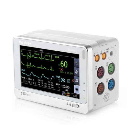
Mindray T1 Service Manual
Patient monitor
Hide thumbs
Also See for T1:
- Quick reference manual (28 pages) ,
- Operator's manual (278 pages) ,
- Operator's manual (286 pages)
Table of Contents
Advertisement
Quick Links
Advertisement
Table of Contents
Troubleshooting

Related Manuals for Mindray T1


Summary of Contents for Mindray T1
- Page 1 T1 Patient Monitor Service Manual...
- Page 3 This manual may refer to information protected by copyrights or patents and does not convey any license under the patent rights of Mindray, nor the rights of others. Mindray does not assume any liability arising out of any infringements of patents or other rights of third parties.
- Page 4 Contents of this manual are subject to changes without prior notice. All information contained in this manual is believed to be correct. Mindray shall not be liable for errors contained herein nor for incidental or consequential damages in connection with the furnishing, performance, or use of this manual.
- Page 5 Exemptions Mindray's obligation or liability under this warranty does not include any transportation or other charges or liability for direct, indirect or consequential damages or delay resulting from the improper use or application of the product or the use of parts or accessories not approved by Mindray or repairs by people other than Mindray authorized personnel.
- Page 6 Contact Information Shenzhen Mindray Bio-Medical Electronics Co., Ltd. Manufacturer: Address: Mindray Building, Keji 12th Road South, Hi-tech Industrial Park, Nanshan, Shenzhen 518057 P.R. China Tel: +86 755 81888998 Fax: +86 755 26582680 Website: www.mindray.com Distributor: Mindray DS USA, Inc. Address:...
- Page 7 Intended Audience This manual is for biomedical engineers, authorized technicians or service representatives responsible for troubleshooting, repairing and maintaining the monitors Contact your local Mindray Service Organization for information on product courses which address service and support for this product. Passwords A password may be required to access different modes.
- Page 8 FOR YOUR NOTES T1 Service Manual...
-
Page 9: Table Of Contents
2.4.3 Rear View ......................................2-6 2.5 System Structure ......................................2-7 2.5.1 Main Unit ......................................2-8 2.5.2 T1 Docking Station and T1 Handle ............................2-10 2.5.3 External Parameter Modules...............................2-11 3 Unpacking and Installation .............................. 3-1 3.1 Unpacking and Checking .................................... 3-1 ... - Page 10 5.5.4 Checking Monitor Information ..............................5-13 6 Troubleshooting ................................6-1 6.1 Introduction ........................................6-1 6.2 Part Replacement ......................................6-1 6.3 Checking Patient Monitor Status ................................6-1 6.4 Checking Software Version ..................................6-1 T1 Service Manual...
- Page 11 6.6.2 Display Failures ....................................6-3 6.6.3 Alarm Problems ....................................6-3 6.6.4 Button Failures ....................................6-3 6.6.5 T1 Docking Station and T1 Handle Failure ..........................6-4 6.6.6 System Running Failure .................................. 6-4 6.6.7 Input/output Interface Failure ..............................6-5 ...
- Page 12 8.8 T1 Handle (115-028440-00)..................................8-9 8.8.1 Exploded View ....................................8-9 8.8.2 Parts List ......................................8-11 8.9 T1 Docking Station (115-028323-00/115-023300-00) ........................8-12 8.9.1 Main Unit ......................................8-12 8.9.2 Dock Top Housing Assembly (115-028363-00) ........................8-14 ...
-
Page 13: Safety
Indicates a potential hazard or unsafe practice that, if not avoided, could result in death or serious injury. CAUTION Indicates a potential hazard or unsafe practice that, if not avoided, could result in minor personal injury or product/property damage. NOTE Provides application tips or other useful information. T1 Service Manual... -
Page 14: Warnings
Protect the equipment from damage caused by drop, impact, strong vibration or other mechanical force during servicing. 1.1.3 Notes NOTE Refer to Operation Manual for detailed operation and other information. 1.2 Equipment Symbols See the T1 Operator’s Manual for information about the symbols used on this product and its packaging. T1 Service Manual... -
Page 15: Theory Of Operation
Theory of Operation 2.1 Introduction The T1 is intended to be used for monitoring, displaying, reviewing, storing and transferring of multiple physiological parameters including ECG, respiration (Resp), temperature (Temp), SpO , pulse rate (PR), non-invasive blood pressure (NIBP), invasive blood pressure (IBP), and carbon dioxide (CO ) of the patient. -
Page 16: Left View
Lock/unlock switch: When the T1 is not connected with the external display, sliding this switch to the right locks/unlocks the touch screen. When the T1 is connected to the external display, sliding this switch to the right switches screen display between T1 and the external display. -
Page 17: Right View
2.2.3 Right View Connector for Temp probe 1 Connector for Temp probe 2 Connector for IBP cable Connector for NIBP cuff Connector for ECG cable Connector for SpO cable Multifunctional connector: outputs analog and defibrillation synchronization signals. Speaker T1 Service Manual... -
Page 18: Bottom View
2.2.4 Bottom View Latch: locks T1 when T1 is in use with a Passport 12m or17m patient monitor, T1 docking station, or T1 handle. Pressing here releases T1 so that you can take it out from the host monitor, T1 docking station, or T1 handle. -
Page 19: Right View
2.4 T1 Docking Station 2.4.1 Left View Symbol: indicates the direction and angle that T1 docking station can rotate when T1 docking station is fixed onto a transverse or a vertical rod. USB connector: connects USB devices, including the USB drive, mouse and keyboard. -
Page 20: Right View
Equipotential grounding terminal VGA connector: connects the external display External device connector: connects T1 to the host monitor through the T1 docking station cable (P/N 009-003591-00 (1 meter) or P/N 009-003592-00 (4 meters)). USB connector: connects USB devices, including the USB drive, mouse and keyboard. -
Page 21: System Structure
T1 Docking Station can be fixed to the bedside for the docking of T1. It provides power for T1 or charging of the installed battery. It can be connected to an external display, mouse, keypad, USB flash memory, Passport 12m or 17m patient monitors, and a wired network. -
Page 22: Main Unit
2.5.1 Main Unit The following figure shows the main unit architecture of T1. Valve assembly SPO2 Multi‐parameter board Backup Extended Infrared board Battery connector battery pack Speaker Main unit multi‐pin connector Main board DC‐IN Antenna LCD and Wi‐Fi touchscreen Note: In this figure, the black blocks are hard wired while the others are flexible wired. - Page 23 2.5.1.4 Infrared Communication Backboard The infrared communication backboard implements infrared communication and transmits signals between the multi-parameter board and the main board. 2.5.1.5 Wi-Fi Module The Wi-Fi module supports wireless networking that is compatible with the 802.11 a/b/g/n standard. T1 Service Manual...
-
Page 24: T1 Docking Station And T1 Handle
T1 handle converter board and T1 handle NIOS board. When T1 is installed to the T1 Docking Station, it is connected to the T1-Dock interface power board through the T1-Dock converter board, thus getting power from the T1-Dock interface board. Besides, T1 can be connected with external devices through the USB connector, external device connector (Mini DB15), VGA, and network connector on the Docking Station. -
Page 25: External Parameter Modules
Board If T1 and an external module are both installed to the T1 handle, the external module is connected to the T1 handle converter board through the T1 handle NIOS board gets power from the battery installed in T1. The T1 handle converter is connected to T1 through the 54 pin connector. - Page 26 FOR YOUR NOTES 2-12 T1 Service Manual...
-
Page 27: Unpacking And Installation
The equipment shall be installed by personnel authorized by Mindray. The software copyright of the equipment is solely owned by Mindray. No organization or individual shall resort to altering, copying, or exchanging it or to any other infringement on it in any form or by any means without due permission. -
Page 28: Preparation For Installation
57.3 to 105.3 57.3 to 105.3 Sidestream CO module Item Operating conditions Storage conditions Temperature (°C) 5 to 40 -20 to 60 Relative humidity (noncondensing) 15% to 95% 10% to 95% Barometric (kPa) 57.3 to 105.3 57.3 to 105.3 T1 Service Manual... -
Page 29: Electrical Requirements
If you run T1 on external DC power, connect T1 with the DC adapter. If you run T1 on battery power, ensure that the battery is sufficiently charged. If you run T1 on T1 Docking Station, connect the power cord of the Docking Station to AC power and check if the power indicator on the Docking Station lights up. -
Page 30: Wireless Network Specification
Panorama central station does not transfer the historical data.) when reconnection at the same time. The wireless functions of all T1 monitors are normal at the same time. The wireless functions of the monitor are normal when the following conditions exist... -
Page 31: Network Setup Overview
3.2.4 Network Setup Overview In the [Network Setup] menu, you can set IP address, subnet mask and gateway. You should not change the patient monitor’s IP address randomly. If you want to know details about IP address setup, contact Mindray Technical Support Department.. -
Page 32: Setting The Wlan Band And Channels
Enter the [IP Address] of the wireless AP in the [WLAN Test >>] menu. Click [Connection Test]. If the designated IP can be successfully connected, the reply time is displayed. If the connection fails, the reply is timeout. T1 Service Manual... -
Page 33: Certificates Maintenance
Select the desired value for [Others]. This sets the service quality of network connection for secondary non-realtime network transactions such as transferring history data from the monitor to the CMS. The value ranges from 0 to7. The greater the value, the higher priority the network transaction. T1 Service Manual... -
Page 34: Setting The Multicast Parameters
Multicast parameters must be configured before use on a network. To set the multicast parameters: Select [Main Menu]→[Maintenance>>]→[User Maintenance>>]→enter the required password.→[Network Setup >>]→[Multicast Setup >>]. Set [Multicast Addr] and [TTL]. Select [Ok] to save the setting. T1 Service Manual... -
Page 35: Hardware And Software Upgrade
Hardware and Software Upgrade 4.1 Hardware Upgrade Only monitors configured with Mindray ECG algorithm can be upgraded with the following hardware upgrade packages. The ECG algorithm configuration remains unchanged after the hardware has been upgraded. 4.1.1 Upgrade Package Upgrade Monitor configuration before... -
Page 36: Hardware Upgrade Method
The antenna should not bend or twist in the slot. When the antenna is in place, press the protective tape down firmly to make sure the antenna is secured onto the main frame. T1 Service Manual... - Page 37 Press the tape down firmly to make sure the cables are tightly secured onto the main frame. Separate the two cables and use tape to secure the cables onto the main frame Install the Cyberlink module PCBA or 5GHz module into the socket on the main board. Cyberlink module PCBA or 5GHz module T1 Service Manual...
-
Page 38: Software Upgrade
Setup>>], and set [Network Type] to [WLAN]. Test if the Wi-Fi function operates properly. 4.2 Software Upgrade Software upgrades must be performed by Mindray, NA authorized service provider. Call Service Dispatch 1 800 288-2121 ext: 7875. T1 Service Manual... -
Page 39: Testing And Maintenance
The testing procedures provided in this chapter are intended to verify that the patient monitor meets the performance specifications. If the patient monitor or a module fails to perform as specified in any test, repairs or replacement must be done to correct the problem. If the problem persists, contact Mindray Technical Support Department. CAUTION ... -
Page 40: Co Leakage Test
Valve T-shape connector Monitor Gas cylinder Open the valve to flow CO and make sure that there is flow sufficient to vent to atmosphere. Verify the realtime CO value is within 5.0±0.3% in the [Calibrate CO2] menu. T1 Service Manual... -
Page 41: Co Calibration
If the calibration is completed successfully, the message [Calibration Completed!] is displayed in the [Calibrate CO2] menu. If the calibration failed, the message “Calibration Failed!” is displayed. If the initial calibration fails, perform a second calibration. If that attempt fails, contact Mindray Technical Support for assistance. T1 Service Manual... -
Page 42: Performance Tests
Inspect the power cord, and module accessories for obvious signs of damage Inspect all external connections for loose connectors, bent pins or frayed cables. Make sure that safety labels and data plates on the equipment are clearly legible. T1 Service Manual... -
Page 43: Ecg Tests
Check the ECG waves are displayed correctly without noise and the displayed HR value is within 80 ± 1 bpm. If the value is not within 80 +/-1 then contact Mindray Technical Support Disconnect each of the leads in turn and observe the corresponding lead off message displayed on the screen. -
Page 44: Spo 2 Test
Check the Pleth wave and PR reading on the screen and make sure that the displayed SpO2 is within 95% and 100%. If you are unable to get the SPO between 95% and 100%, contact Mindray Technical Support. Remove the SpO sensor from the finger and make sure that an alarm of SpO Sensor Off is triggered. - Page 45 6. NOTE You can use an NIBP simulator to replace the squeeze bulb and the reference manometer to perform the test. You can use an appropriate cylinder and a cuff instead of the rigid vessel. T1 Service Manual...
- Page 46 Raise the pressure in the rigid vessel to 250 mmHg with the squeeze bulb. Then, wait for 5 seconds to let the measured values becoming stable. Record the current pressure value, and then, record the pressure value after 60s. Compare the two pressure values and make sure the difference is not greater than 6 mmHg. T1 Service Manual...
-
Page 47: Temp Test
Connect the two pins of any Temp connector of a module to the two ends of the resistance box using 2 wires. Set the resistance box to 1354.9Ω (corresponding temperature is 37ºC). Verify that the displayed value is within 37 ± 0.1ºC. If the temperature is not within 37 ± 0.1ºC, contact Mindray Technical Support. -
Page 48: Analog Output Performance Test
Press the power on/off switch to switch on T1. The battery indicator lights up. When T1 is powered through DC adapter: Insert the battery in the battery compartment and connect T1 to the AC to DC adapter. Verify the external power supply indicator and battery indicator light up. -
Page 49: Touchscreen Calibration
Press the power on/off switch to switch on T1. T1 performs a self-test as soon as being powered on. During the self-test, the alarm lamp turns yellow and red, and then turns off; T1 beeps once. This indicates that the visual and audible alarm indicators operate properly. -
Page 50: Network Print Test
5.4.5.2 Battery Performance Test Turn off the monitor. Disconnect the monitor from the external power supply if DC adapter or T1 docking station is connected. Install the battery in the monitor. Connect the external power supply and allow the battery to be charged uninterruptedly till it is fully charged. -
Page 51: Print Function Test
5.5.3 Checking Software Version In the [Factory Maintenance] menu, select [Software Version] to show software version information. 5.5.4 Checking Monitor Information In the [Factory Maintenance] menu, select [Monitor Information] to show the status of the patient monitor. T1 Service Manual 5-13... - Page 52 FOR YOUR NOTES 5-14 T1 Service Manual...
-
Page 53: Troubleshooting
In this chapter, patient monitor problems are listed along with possible causes and recommended corrective actions. Refer to the tables to check the patient monitor, identify and eliminate these problems. For more information on troubleshooting, contact Mindray Technical Support Department. 6.2 Part Replacement Printed circuit boards (PCBs), major parts and components in patient monitors are replaceable. -
Page 54: Checking Technical Alarms
Before troubleshooting the patient monitor, check for technical alarm messages. If an alarm message is presented, eliminate the technical alarm first. For detailed information on technical alarm messages, possible causes and corrective actions, refer to the T1 Operator’s Manual. 6.6 Troubleshooting Guide 6.6.1 Power On/Off Failure... -
Page 55: Display Failures
Speaker is defective Replace the speaker. Main board is defective Replace the main board. 6.6.4 Button Failures Symptoms Possible Cause Correction Action The lock/unlock switch does not respond. Main board is defective Replace the main board. T1 Service Manual... -
Page 56: T1 Docking Station And T1 Handle Failure
Replace the T1 handle NIOS board modules T1 handle converter board Check the connection between the T1 handle defective converter board and the T1 handle NIOS board. If properly connected, replace the T1 handle converter board. Main board defective Replace the main board... -
Page 57: Input/Output Interface Failure
Main board is defective Replace the main board. No +5 VDC/+12 VDC Main board failure 1. Restart T1. output 2. If T1 does not turn on, replace the main board. Power Communication Main board failure Replace the main board. error is reported NOTE ... -
Page 58: Wi-Fi Related Problems
Corrective Action The monitor is frequently off The Wi-Fi signal is unstable in the 1. Check if the Mindray recommended wireless AP is used. If line or disconnects from the operating area. not, verify the AP effective transmission rate meets the Wi-Fi network. - Page 59 AP. 4. Check for IP address conflicts. If any, set the IP addresses correctly. 5. Check if Mindray recommended wireless AP is used. If not, verify the AP effective transmission rate meets the throughput requirements of the connected devices.
-
Page 60: Wired Network Related Problems
Incorrect IP address setting Configure a fixed IP address in range C as specified for the patient monitor. We recommend not performing software upgrade whenT1 is connected to a network having multiple PCs. Main board defective Replace the main board. T1 Service Manual... -
Page 61: Disassembly And Repair
Place the screws and parts from the same module together to facilitate reassembling. To reassemble the equipment, first assemble the assemblies, and then the main unit. Carefully route the cables. Make sure all O rings and seals are installed during reassembling. T1 Service Manual... -
Page 62: Disassembling T1 Main Unit
7.3 Disassembling T1 Main Unit 7.3.1 Removing the Battery Door and Battery Open the battery door. If a battery is installed, take out the battery. Open the battery door Use your finger to press the battery door tether and then detach the battery door, as shown below: Press the retaining clip to detach the battery door from the 7.3.2 Disassembling the Rear Housing Assembly... - Page 63 When disassembling the infrared communication board, use tweezers to raise the board, and then remove the board to prevent from bending the pins. Before reassembling the board, check if the pins of the main board and multi-parameter board are ok. T1 Service Manual...
- Page 64 Detach the tubing connecting the parameter module and the pump and valve assembly from their connectors. Detach the tubing from the connector Loosen the parameter board latch and slide the parameter board to the right to remove it from the main frame. Loosen the parameter board latch T1 Service Manual...
- Page 65 Remove the insulating plate. Unscrew the two plastic M3 hex nuts and the two M3×12 plastic double-screw bolts. Detach the tubing. Unscrew the two plastic M3 hexagon nuts and Detach the air tubing the two M3×12 plastic double-screw bolts Insulating plate T1 Service Manual...
-
Page 66: Disassembling The Front Housing Assembly
See the pictures below for details. Unscrew the four PT3×10 screws Cut the adhesive tape and 5GHz Wi-Fi module remove the Wi-Fi antenna has one antenna connector only. Disconnect the fan cable from this socket Analog Output cable T1 Service Manual... - Page 67 Use tape to secure the Wi-Fi antenna back in its original location after replacing the antenna. When reinstalling the SD card, be sure to secure the SD card on the tray by using the adhesive tape. See the pictures below. T1 Service Manual...
- Page 68 Withdraw the analog out cable from the hole beside the fan on the main frame, and then disconnect the NIBP tubing. Withdraw the analog out cable Disconnect the NIBP tubing from the hole beside the fan Unscrew the three M3×8 screws that secure the parameter connector assembly and remove the assembly from the main frame. T1 Service Manual...
- Page 69 Unscrew the three M3×8 screws T1 Service Manual...
- Page 70 7.3.3.4 Disassembling the Pump, the Dump Valve and the Linear Valve Remove the adhesive tape that secure the valve and pump cable. Remove the cable from the cable holder. Remove the adhesive tape 7-10 T1 Service Manual...
- Page 71 Remove the pump and the valves. Before removing the pump and the valves, take the valve and pump cables from the main frame to avoid damaging the cables. Dump and linear valves Pump T1 Service Manual 7-11...
-
Page 72: Disassembling The T1 Docking Station
Do not press on the fans core. 4 fan mounting pads on bottom 7.4 Disassembling the T1 Docking Station Removing the Bottom Board Unscrew the four M3×8 screws that attach the bottom board, and remove the bottom board as shown below: Unscrew the four M3×8 screws... -
Page 73: Disassembling The Right Housing Assembly
7.4.1.1 Removing the Rotating Plate Unscrew the four M3×8 screws and take out the right housing strengthen board. Then remove the rotating plate from the right housing. Unscrew the four M3×8 screws T1 Service Manual 7-13... -
Page 74: Removing The Converter Board
Take out the converter board PCBA cable and converter board PCBA from the top housing. Then remove the connector from the socket of converter board PCBA. Remove the connector from the socket of converter board PCBA. 7-14 T1 Service Manual... -
Page 75: Disassembling The Connector Assembly
7.4.3.1 Removing Connector Board PCBA Disconnect the power board cable from the connector board, unscrew the two M3×6 screws and take out the connector board PCBA. Disconnect the power board cable from the connector board unscrew the two M3×6 screws T1 Service Manual 7-15... -
Page 76: Disassembling The Top Housing Assembly
7.4.4 Disassembling the Top Housing Assembly 7.4.4.1 Removing the Locating Pin Unscrew the two M3×6 screws, remove the locating pin pressing plate and take out the locating pin and locating pin spring. Unscrew the two M3×6 screws 7-16 T1 Service Manual... -
Page 77: Disassembling The T1Handle
7.4.4.2 Removing the Indicator Slide the LED bracket upward to remove the top housing. Then remove the indicator. The yellow cable is for AC power indicator while the black one is for T1 connection indicator. Slide the LED bracket upward 7.5 Disassembling the T1Handle... -
Page 78: Removing The Infrared Board
Unscrew the M2.5×8 screw and take out the unlock lever, module A button, and the spring. Unscrew the M2.5 ×8 screw 7.5.2 Removing the Infrared Board Unscrew the M3×8 screw, Loosen the retaining clip and remove the flexible cable from the PCBA socket. Unscrew the M3×8 screw Remove the flexible cable 7-18 T1 Service Manual... -
Page 79: Removing The Converter Board
7.5.3 Removing the Converter Board Unscrew the two PT3×10 screws and take out the T1 handle socket bracket. Unscrew the two PT3×10 screws Unscrew the two M2×8 screws, take out the waterproof sheath of the connector, and remove the converter board PCBA from the T1 handle socket bracket. -
Page 80: Removing Contact Screws
7.5.4 Removing Contact Screws Press on the contact screw with your hand, and unscrew the M3 hexagon nut. Then take out the contact screw and spring. Unscrew the M3 hexagon nut. 7-20 T1 Service Manual... -
Page 81: Parts
The part number listed in the Parts List is only for checking the FRU part number which is also included in the Parts List. Please provide the FRU part number if you want to purchase the spare parts. T1 Service Manual... -
Page 82: Main Unit
Battery door 115-018386-00 The battery door is included in the rear cover assembly Rear cover assembly 115-018386-00 Screw hole cover Parameter assembly 051-001969-00 Without 12 lead ECG 051-001970-00 With 12 lead ECG Crosshead tapping screw, pan head, T1 Service Manual... -
Page 83: Front Cover Assembly (115-022667-00)
Description FRU part number Remark PT3×10 Trestle module 115-021319-00 Parameter connector assembly 115-010239-01 Nellcor SpO2 115-010240-01 Masimo SpO2 8.3 Front Cover Assembly (115-022667-00) 8.3.1 Exploded View T1 Service Manual... -
Page 84: Parts List
Front Cover Power button Silicone base for power button 9281 Main board 115-024222-00 SD storage card (SLC) 023-000755-00 T1 handle Waterproof cover Silicone seal Screen lock/unlock button Spring Screen lock/unlock slider Lens for alarm LED Lens for indicating LED LED cover... -
Page 85: Rear Cover Assembly
8.4 Rear Cover Assembly 8.4.1 Exploded View 8.4.2 Parts List Description FRU part number Rear cover 115-018386-00 Slot cover Guide strip Infrared lens Contact nut Contact screw Handle T1 Service Manual... -
Page 86: Main Frame Assembly
Battery direction label Air valve 801-9281-00004-00 Shock absorption cushion for pump 801-9281-00003-00 Screw, pan head, Phillips M3×8 NIBP mounting board 043-001737-00 Pump, PI6B07 801-9281-00003-00 630F reducer 801-9281-00005-00 4-channel silicone tube Connector Silicone tube Connector Antenna 115-010234-00 (2.4GHz) or T1 Service Manual... -
Page 87: Parameter Connector Assembly
Refer to the equipment’s parameter Parameter panel 115-010239-01 module configuration to choose Speaker 115-010240-01 correct FRU part number, see 8.2.2 Speaker cushion Parts List. Connector fastening plate Multifunctional connector socket, 9281 Screw, self-tapping, PT2.6×6 Connector board PCBA T1 Service Manual... -
Page 88: Parameter Assembly
Description FRU part number Remark TEMP connector housing IBP connector housing ECG connector housing NIBP external pedestal SpO2 connector housing Silicon jacket Steal ball, φ2.5 NIBP internal pedestal (hexagon) 8.7 Parameter Assembly 8.7.1 Exploded View T1 Service Manual... -
Page 89: Parts List
Plastic hex bolt Phillips screw, pan head, M3×4 board 115-022691-00 Masimo SpO2 115-010243-00 Nellcor SpO2 Multi-parameter module 051-000974-01 5-lead ECG 051-000975-01 12-lead ECG Plastic hex nut, M3×0.5 SpO2 board insulator 8.8 T1 Handle (115-028440-00) 8.8.1 Exploded View T1 Service Manual... - Page 90 8-10 T1 Service Manual...
-
Page 91: Parts List
Elastic clip Contact screw Washer-Grade A GB/T96.1-2002 Washer for hexagonal nut Infrared lens Contact spring T1 handle male plug cover T1 handle converter board PCBA 051-001366-00 T1 handle receptacle bracket Screw, GB/T818-2000 M28 T1 handle female plug cover T1 handle NIOS board 051-001367-00 Screw, PT310... -
Page 92: T1 Docking Station (115-028323-00/115-023300-00)
Description FRU part number Release button T1 handle compression spring T1 handle unlock lever Screw, GB/T818-2000, M2.58 Decorative label Screw Cover 8.9 T1 Docking Station (115-028323-00/115-023300-00) 8.9.1 Main Unit 8.9.1.1 Exploded View 8-12 T1 Service Manual... - Page 93 Screw cover 2 Screw, M38, NI-P Dock Right housing assembly ESD insulator Screw, M36, NI-P Press plate for Dock converter board T1 Dock converter board PCBA 051-001368-00 T1 handle male plug cover Dock top housing assembly 115-030316-00 Power cable hook...
-
Page 94: Dock Top Housing Assembly (115-028363-00)
8.9.2.2 Parts List Description FRU part number Dock indicator connection cable 009-003299-00 Screw, M36, NI-P T1 handle locating pin plate T1 handle locating pin waterproof pad Pin spring T1 handle locating pin 043-003181-00 Dock top cover Dock decorative label LED bracket... -
Page 95: Dock Right Housing Assembly (115-028364-00)
8.9.3 Dock Right Housing Assembly (115-028364-00) 8.9.3.1 Exploded View 8.9.3.2 Parts List Description FRU part number Dock rotating plate label Dock rotating plate Dock right housing Dock right housing bracket Combination bolt, M38 T1 Service Manual 8-15... -
Page 96: Dock Connector Assembly (115-020747-00/115-018067-00)
8.9.4 Dock Connector Assembly (115-020747-00/115-018067-00) 8.9.4.1 Exploded View 8.9.4.2 Parts List Description FRU part number T1 Dock interface board PCBA 051-001369-00/051-001509-00 Dock interface board bracket Network connector insulator Grounding terminal Lock washer, #6 AC inlet and cable 009-003698-00 Power board insulator... -
Page 97: Other Replaceable Parts
Analog out cable 009-002208-00 T1 adapter cable 009-003302-00 Cable, transfer board to interface board 009-003300-00 T1 network upgrade cable 009-003726-00 T1 network upgrade tool assembly 115-020584-00 Adhesive tape, for SD card 047-011750-00 Masimo SpO2 upgrade kit 115-023940-00 Nellcor SpO2 upgrade kit 115-023941-00... - Page 98 FOR YOUR NOTES 8-18 T1 Service Manual...
-
Page 99: A Electrical Safety Inspection
No physical damage to the enclosure and accessories. No physical damage to meters, switches, connectors, etc. The enclosure and accessories No residue of fluid spillage (e.g., water, coffee, chemicals, etc.). No loose or missing parts (e.g., knobs, dials, terminals, etc.). T1 Service Manual... -
Page 100: Device Labeling
When patient electrically-connected PCBA is Test items: 1, 2, 3, 4, 6, 7, 8 repaired or replaced When both power supply PCBA and patient Test items: 1, 2, 3, 4, 5, 6, 7, 8 electrically- connected PCBA are repaired or replaced T1 Service Manual... -
Page 101: Electrical Safety Inspection Test
BF applied part: NC:100μA, SFC: 500μA Mains on Applied Part Leakage Max: CF applied part: 50μA BF applied part: 5000μA Patient Auxiliary Current Normal condition(NC) Max: CF applied part: NC:10μA, SFC: 50μA BF applied part: NC:100μA, SFC: 500μA T1 Service Manual... - Page 102 FOR YOUR NOTES T1 Service Manual...
- Page 104 PN: 046-005808-00 (4.0)
Need help?
Do you have a question about the T1 and is the answer not in the manual?
Questions and answers