Mindray TE7 Operator's Manual
Diagnostic ultrasound system
Hide thumbs
Also See for TE7:
- Operator's manual (103 pages) ,
- Operator's manual (312 pages) ,
- Operator's manual (337 pages)
Table of Contents
Advertisement
Quick Links
Advertisement
Table of Contents

Related Manuals for Mindray TE7


Summary of Contents for Mindray TE7
- Page 1 TE7/TE5 Diagnostic Ultrasound System Operator’s Manual [Basic Volume]...
-
Page 3: Table Of Contents
Contents Contents ..........................i Intellectual Property Statement ......................I Responsibility on the Manufacturer Party ..................I Warranty ............................II Exemptions ........................... II Customer Service Department ..................... II Important Information ........................III About This Manual ........................... III Notation Conventions ........................IV Operator’s Manuals .......................... -
Page 4: Table Of Contents
Imaging Mode ........................5-1 B Mode Image Optimization ....................5-4 M Mode Image Optimization ....................5-10 Color Mode Image Optimization ..................5-12 Power Mode Image Optimization ..................5-17 PW/CW Doppler Mode ....................... 5-19 Contrast Imaging ........................ 5-26 Anatomical M Mode ......................5-33 TDI ............................ -
Page 5: Table Of Contents
11.2 Verify Connectivity ......................11-10 11.3 DICOM Services ........................ 11-11 11.4 DICOM Media Storage ..................... 11-15 11.5 Structured Report ......................11-17 11.6 DICOM Task Management ....................11-17 12 Setup........................12-1 12.1 System Preset ........................12-2 12.2 Exam Related Preset ....................... 12-22 12.3 Network Related Preset .................... - Page 7 Contents of this manual are subject to change without prior notice. All information contained in this manual is believed to be correct. Mindray shall not be liable for errors contained herein or for incidental or consequential damages in connection with the furnishing, performance, or use of this manual.
- Page 8 FOR ANY PARTICULAR PURPOSE. Exemptions Mindray's obligation or liability under this warranty does not include any transportation or other charges or liability for direct, indirect or consequential damages or delay resulting from the improper use or application of the product or the use of parts or accessories not approved by Mindray or repairs by people other than Mindray authorized personnel.
-
Page 9: Important Information
7. Important data must be backed up on external memory media. 8. Mindray shall not be liable for loss of data stored in the memory of this system caused by operator error or accidents. 9. This manual contains warnings regarding foreseeable potential dangers, but you shall also be continuously alert to dangers other than those indicated. - Page 10 Notation Conventions In this operator’s manual, the following words are used besides the safety precautions (see “Safety Precautions”). Please read this operator’s manual before using the system. NOTE: Indicates information of interest to users of this system regarding exceptional conditions or operating procedures. U.S.A.
- Page 11 [Items in menu] -> [Items in submenu]: select a submenu item following the path. Product Differences Product model Feature Double Dist √ √ Depth √ √ Parallel line √ √ Spline length √ NOTE: Only TE7 is available in Canada.
-
Page 13: Safety Precautions
Safety Precautions 1.1 Safety Classifications According to the type of protection against electric shock: Class I equipment + Internally powered equipment According to the degree of protection against electric shock: Type-BF applied part According to the degree of protection against harmful ingress of water: The main unit is rated IPX0 The probes are rated IPX7 The foot switch (can be applied in the operating room) is rated IPX8. -
Page 14: Meanings Of Signal Words
1.2 Meanings of Signal Words DANGER WARNING CAUTION In this manual, the signal words , NOTE and Tip are used regarding safety and other important instructions. The signal words and their meanings are defined as follows. Please understand their meanings clearly before reading this manual. - Page 15 You must use the power adapter provided with the system; otherwise electric shock may result. You can only use the power supply method provided by Mindray, other power supply modes (e.g. using a UPS) may result in electric shock. Connect the protective grounding conductor before turning ON the system.
- Page 16 Do not use an aftermarket probe other than those specified by Mindray. The probes may damage the system, causing a profound failure, e.g. a fire in the worst case. Do not subject the probes to knocks or drops. Use of a defective probe may cause an electric shock.
- Page 17 If the circuit protector is tripped, it indicates that the system or a peripheral device was improperly shut down and that the system is unstable. You cannot repair the system under this circumstance and must call the Mindray Customer Service Department or sales representative. Safety Precautions 1-5...
- Page 18 There is no risk of high-temperature burns during normal ultrasound examinations. It is possible for the surface temperature of the probe to exceed the body temperature of a patient due to environmental temperature and exam mode combinations. Apply the probe only for a period of time required for the purpose of diagnosis.
- Page 19 If the system is used in a small room, the room temperature may rise. Please provide proper ventilation and free air exchange. To dispose of the system or any part, contact Mindray Customer Service Department or sales representative. Mindray is not responsible for any system content or accessories that have been discarded improperly.
- Page 20 Please use the disinfection or sterilization solution that recommended in this operator’s manual; otherwise Mindray will not be liable for damage caused by other solutions. If you have any questions, please contact Mindray Customer Service Department or sales representative.
- Page 21 The probe sheath contains natural rubber that can cause allergic reactions in some individuals. Do not use pre-lubricated condoms as a sheath. Lubricant may not be compatible with the transducer material and damage may result. Transducer damage may be caused by inappropriate gel, detergent or cleanser: Do not soak or saturate transducers with solutions containing alcohol, bleach, ammonium chloride compounds, acetone or...
-
Page 22: Latex Alert
2. Ambient conditions: To prevent the probe from being damaged, do not use it where it will be exposed Direct sunlight or X-rays Sudden changes in temperature Dust Excessive vibration Heat generators Use the probes under the following ambient conditions: ambient temperature: 0°... -
Page 23: Warning Labels
Warning Labels Warning labels are attached to this system to call your attention to potential hazards. The symbol on warning labels indicates safety precautions. The warning labels use the same signal words as those used in the operator’s manual. Read the operator’s manual carefully before using the system. -
Page 25: System Overview
System Overview Intended Use TE7/TE5 Diagnostic Ultrasound System is applicable for adults, pregnant women, pediatric patients and neonates. It is intended for use in fetal, abdominal, intra-operative (abdominal, thoracic, and vascular), pediatric, small organ (breast, thyroid, testes), neonatal and adult cephalic, trans-esoph. -
Page 26: System Configuration
2.2.3 Environmental Conditions Operating conditions Storage and transportation conditions Ambient temperature 0° C~40° C -20° C~55° C Relative humidity 30%~85% (no condensation) 20%~95% (no condensation) Atmospheric pressure 700hPa~1060hPa 700hPa~1060hPa WARNING: Do not use this system in conditions other than those specified. 2.2.4 Dimensions and Weight Dimensions (including probe holder): 130±... - Page 27 2.3.2 Probes and Needle-guided Brackets Available Probe Probe Type Intended Use Region Applied model C5-2s Convex Fetal, abdominal, pediatric, peripheral vessel Body surface Abdominal, pediatric, neonatal cephalic, C11-3s Convex Body surface Cardiac Pediatric, peripheral vessel Ophthalmic, Abdominal, Pediatric, Small L12-4s Linear organ, musculo-skeletal (conventional, Body surface...
- Page 28 Probe Probe Type Intended Use Region Applied model Abdominal, pediatric, neonatal cephalic, adult Body surface P7-3s Phased cephalic, cardiac adult, cardiac pediatric Fetal, Abdominal, Pediatric, Neonatal Body surface SP5-1s Phased Cephalic, Adult Cephalic, Cardiac Adult, Cardiac Pediatric Abdominal, Pediatric, small organ (breast, Body surface L9-3s Linear...
- Page 29 L14-5Ws CIVCO 698-007 L14-5Ws CIVCO 698-012 Note: The disposable needle-guided brackets are not configured or sold by Mindray. The user can purchase them based on the specific needs. See CIVCO for the use of each disposable needle- guided bracket. NOTE: Some features may not be available in some countries due to pending regulatory approvals.
-
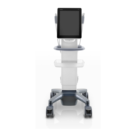
Page 30: Appendix D Trolley And Accessories
2.3.3 Options Item Remarks Footswitch Types: 2-pedal/3-pedal Trolley See chapter “Appendix D Trolley and Accessories” for details. Wall mount/Table stand After the wall mount/table stand is configured, power adapter and cables should be configured. Power adapter Table stand or wall mounting bracket should be configured. - Page 31 Item Remarks DICOM MPPS DICOM OB/GYN SR DICOM Vascular SR DICOM Cardiac SR DICOM Query/Retrieve DICOM Breast SR Free Xros M Not applicable for Canada. Tissue Doppler Imaging Cardiac Package should be configured. Vascular Package should be configured. Auto EF Cardiac Package should be configured.
-
Page 32: Introduction Of Each Unit
Parts that can be used within patient environment: Main unit; Probes; Footswitch; Printers: MITSUBISHI P95DW-N, SONY UP-D25MD, SONY UP-D898MD, SONY UP- X898MD. NOTE: If the ultrasound system cannot recognize the SONY UP-X898MD and SONY UP-D898MD printers automatically, you may need to change the settings on the printer: push <PUSH ENTER>... - Page 33 Name Function Operator-system interface or control; displays the image and parameters during the scan. : Battery status indicator. Charging status: It illuminates in orange when batteries are charging; It illuminates in green when batteries are charged fully. Discharging status: ...
-
Page 34: Symbols
You can use a HDMI-to-DVI adapter for outputting to a display with DVI input. When connecting TE7/TE5 with an external display or recording devices via HDMI, choose a right output setting resolution ([Setup] ->[System] ->[Peripheral] -> [Display]), and please make sure the scan rate of 60Hz progressive is supported by the external device, otherwise malfunction may result. - Page 35 Symbol Description Probe socket Power consumption Maximum load for printer bracket on the trolley Trolley input Trolley output Maximum load for storage bin on the trolley System Overview 2-11...
-
Page 37: System Preparation
System Preparation 3.1 Move/Position the System Read and understand the safety precautions before positioning the system to ensure the safety of both the operator and the devices. 1. Switch off the power, and pull out the power plug. 2. Disconnect all cables from off-board peripheral devices. 3. -
Page 38: System Maintenance
If the system begins to function improperly, immediately stop scanning. If the system continues to function improperly, fully shut down the system and contact the Mindray Customer Service Department or a sales representative. If you use the system in a persistent improperly functioning state, you may harm the patient or damage the equipment. - Page 39 WARNING: If you find anything not functioning properly, this may indicate that the system is defective. In this case, shut down the system immediately contact Mindray Customer Service Department or sales representative. NOTE: When you start the system or switch between transducers, you may hear clicking sounds –...
- Page 40 3.2.3 Standby To enter standby: Select [Setup] -> [System] -> [General] to set the time for screensaver and standby. If the system is not carrying out an operation, the screensaver appears after the screensaver delay period. If there is still no operation, the system enters standby after the standby delay period.
-
Page 41: Appendix B Battery
Connecting the Power Cord This system can work normally only when it is connected to the external power supply or the battery capacity is sufficient. 3.3.1 Connecting Power 1. Connect the connector of the power adapter to the adapter port in the system. 2. -
Page 42: Connecting A Probe
When connecting or disconnecting a probe, place it in the proper position to prevent the probe from falling off or becoming damaged. Only use probes provided by Mindray. Aftermarket probes may result in damage or cause a fire. 3.4.1 Connecting a Probe... -
Page 43: Connecting The Footswitch
NOTE: If the USB flash drive cannot be recognized by the system, please try disconnecting and then connecting again several times, or try another USB flash drive. If the problem still exists, please contact Mindray service engineer. System Preparation 3-7... -
Page 44: Installing A Graph/Text Printer
Installing a Graph/Text Printer Connecting a local printer NOTE: Printers listed in “2.3.4 Peripherals Supported” chapter have drivers installed already. As shown in the figure below, a graph / text printer has a power cord and data cable. The power cord should be directly plugged into a well-grounded outlet. - Page 45 NOTE: See the printer’s operation manual to select the port, or try to use the default port of the system. 6. Tap [Have Disk] to find the driver path (the installation type should be WIN7 64), and then tap [Next] to install the driver. 7.
-
Page 46: Installing A Video Printer
Installing a Video Printer The system support video printers, consist of the B/W digital printers and color digital printers. 1. Position the printer in the proper place. 2. Plug the printer power cord into an appropriate outlet. 3. Use a USB cable to connect between the system's USB port and the printer's USB port. 4. -
Page 47: Display Position Adjustment
3.10 Display Position Adjustment Gently hold the bottom edge of the display when adjusting its position. When positioned vertically, the display can be tilted for 50° backward and 20° forward. System Preparation 3-11... -
Page 48: Basic Screen & Operation
3.11 Basic Screen & Operation 3.11.1 Screen Display Probe model, acoustic output value and Parameter area MITI index iNeedle iTouch Frequency adjustment TGC control Operating panel Patient Information area System status icon System tool bar Gain control Depth control 3-12 System Preparation... - Page 49 3.11.2 Operating panel Operating panel located under the image area; consists of imaging mode buttons, menu area and exam related buttons. 1. Imaging mode area Tap imaging buttons to start imaging. 2. Menu area Imaging parameter menu: swipe the menu downwards/upwards to see parameter controls; ...
- Page 50 3.11.3 iVocal Before enabling the iVocal function, ensure that the microphone device and the ultrasound system is properly connected through the USB extension wire. Tips: If the microphone is not to be used for the moment, you can put the microphone into the vacant probe holder temporarily.
- Page 51 Currently, only wireless microphone devices can be inserted to the system for inputting vocal commands. Tap [iVocal] to exit the Audio Control menu. Setup Tap the icon in the Audio Command menu to check the system recognizable commands and enter the iVocal Setup menu.
- Page 52 that are already exited in the system but represent different functions are not supported to be added. Test: Tap [Test] and input a vocal command to the microphone device. After the vocal command is recognized, the Success Rate is displayed in fraction. Tap [Test] again to close the vocal command test.
- Page 53 Icon Function Audition the vocal command Delete the vocal command Rename the vocal command Add the failure time by 1 Clear the Success Rate test record of the selected vocal command System Preparation 3-17...
-
Page 55: Exam Preparation
Exam Preparation A patient exam can be started under the following situations: New patient information: to start a new patient exam, patient information must first be entered. New exam: to start a new exam for patient who is already registered, the recorded information can be obtained through either iStation or Worklist. - Page 56 4.1.1 New Patient Information The Patient Info screen is shown as follows: 4-2 Exam Preparation...
- Page 57 Tap to select the desired field. The field box is highlighted and a flashing cursor appears. Information can be entered or selected from the options. Information includes: 1. General information Patient ID The Patient ID is generated automatically by the system after starting a new patient, and can be modified manually.
- Page 58 Exam-specific information: Exam Type Information Description Height General information Weight BSA (body After the height and weight are entered, the system will surface automatically calculate the BSA based on the formula which is (Abdomen) area) set via [Setup] -> [System] -> [General]. Calculate the gestation age (GA) and estimated delivery date (EDD) based on the last menstrual period (LMP), date of conception (DOC), in vitro fertilization (IVF), basic body...
- Page 59 Exam Type Information Description BP(R) (blood Input right blood pressure. pressure) Serum PSA PPSA (Urology) coefficient: SMP (Small None Parts) Breast None 3. Functional controls: [iStation]/[Worklist]: imports patient data from iStation or DICOM Worklist. See chapter “4.1.2 Retrieve Patient Information” for details. [Done]: saves the patient data entered and exits the screen.
- Page 60 4.1.2.2 Retrieve from Worklist Worklist is an option. To use Worklist function, you have to configure DICOM Basic and DICOM Worklist options. When the DICOM basic package is configured and the Worklist server has been set, tap [Worklist] in the Patient Info screen to query or import the patient data. (For details about the Worklist server setting, see chapter “11.1.3.3 DICOM Worklist Preset”...
-
Page 61: Select Exam Mode And Probe
3. Enter the search condition: Set query criteria from Patient ID, Patient Name, MRN, Scheduled Station AE Title, Worklist Server, Modality Type or Exam Date. Or select the search key, enter the keywords, then tap [Query] to search. To reset the criteria, tap [Clear]. ... -
Page 62: Select The Imaging Mode
Tap [Exit] to cancel the selection and exit the screen. Tap and hold any exam mode until it floats, and then drag to change the exam mode list sequence. Tap [A-Z Sort] to sort exam modes by alphabetical order for each probe. Select the Imaging Mode Enter the imaging mode by tapping imaging buttons at the right part of the operating panel. -
Page 63: Image Optimization
Image Optimization The images displayed in this system are for WARNING: reference only. Mindray is not responsible for the correctness of diagnostic results. Tissue Harmonic Imaging does not use contrast agents. Imaging Mode 5.1.1 Switching Between Imaging Modes On the operating panel, tap imaging mode buttons on the right to switch the mode. - Page 64 See the following imaging chapters for details. 5.1.3 Quickly Saving Image Settings Create a new exam mode using current image settings (user-defined exam mode): 1. Tap [Quick Save] in the image menu to bring out the Quick Save dialogue box. 2.
- Page 65 Check image parameter and change layout: 1. Tap [Edit] to enter the screen for checking the current image menu display for the current exam mode of the particular probe. 2. Tap and hold any parameter until it floats, then you can: Drag upwards/downwards to change its position on the image menu;...
-
Page 66: B Mode Image Optimization
B Mode Image Optimization B mode is the basic imaging mode that displays real-time images of anatomical tissues and organs. 5.2.1 Basic Procedures for B Mode Imaging 1. Enter the patient information. Select an appropriate probe and exam mode. 2. Tap [B] on the right side of the operating panel to enter B mode. 3. - Page 67 Operations Drag the [Gain] control on the right part of the image area to adjust the gain. Or, You can change gain value slightly by tapping on the gain control bar directly Effects Increasing the gain will brighten the image and you will see more received signals.
- Page 68 Focus Description Refers to adjusting the focus of the ultrasonic beams, using the symbols which are displayed to the right of the image. Operations Adjust the focus number through [Focus Number] on the menu. Tap [-] or [+] to change the value slightly or drag the control directly. Drag on the right part of the image area to change the focus position.
- Page 69 iBeam (Spatial Compound Imaging) Description This function is used to superimpose and average images of different steer angles to achieve image optimization. Operations Adjust through [iBeam] on the menu. The system provides different levels of iBeam effect. Off represents no iBeam. Effects Images can be optimized with less spot noise and higher resolution, so that more details for the structure are revealed.
- Page 70 Line Density Description The function determines the quality and information of the image. Operations Adjust through [Line Density] on the menu. There are four levels of line density available: UH, M, H, L. Effects The higher the line density, the higher the resolution. Impacts The higher the line density, the lower the frame rate.
- Page 71 Echo Boost Description This function can improve contrast and decrease noise, so that a much clearer boundary can be seen. Operation Set [Echo Boost] to be “On” to turn the function on. Impacts This function is only available using the phased probe in cardiac exam mode (probe P7-3Ts does not support this function) Patient Temperature Description If the current active probe is P7-3Ts, the parameter will display under the B mode...
-
Page 72: M Mode Image Optimization
M Mode Image Optimization 5.3.1 Basic Procedures for M Mode Imaging 1. Select a high-quality image during B mode scanning, and adjust to position the area of interest in the center of the B mode image. 2. Tap [M] on the right side of the operating panel to enter M sampling line status, and drag the sampling line to the desired position. - Page 73 Speed Description This function is used to set the scanning speed of M mode imaging, and the real- time speed value is displayed in the image parameter area in the top-left corner of the screen. Operations Adjust through [Speed (mm/s)] on the menu. There are 6 levels of scan speed available.
-
Page 74: Color Mode Image Optimization
Operations Adjust through [M Soften] on the menu. The system provides 4 levels of M Soften adjustment: the bigger the value the stronger the effect. Color Mode Image Optimization The Color mode is used to detect color flow information, and the color is designed to judge the direction and speed of blood flow. - Page 75 5.4.3 Color Mode Image Optimization Color Gain Description Refers to the overall sensitivity to flow signals. This function is used to adjust the gain in Color mode. The real-time gain value is displayed in the image parameter area in the top-left corner of the screen. Operations Drag the [Gain] control on the right part of the image area to adjust the gain.
- Page 76 Effects This function is used to adjust the scan angle of linear probes, so as to change the angle between the transmitting beam and flow direction. Impacts Steer is only valid for linear probes. Line Density Description Line density determines the quality and information of the image. Operations Adjust through [Line Density] on the menu.
- Page 77 Scale Description This function is used to adjust the speed range of the color flow, which is adjusted using the PRF in the system. The real-time PRF value is displayed in the image parameter area in the top-left corner of the screen. Operations Use [Scale] to adjust PRF values.
- Page 78 Operations Adjust through [WF] on the menu. There are 8 levels of wall filter function available. Select the value according to the actual situation. Impacts Flow signals may be missing. Priority Description This function is used to set the levels of the flow display and to display the grayscale signal or color signal.
-
Page 79: Power Mode Image Optimization
Power Mode Image Optimization Power mode provides a non-directional display of the blood flow in terms of intensity as opposed to flow velocity. DirPower (Directional Power mode) provides additional information of the flow direction toward or away from the probe. 5.5.1 Basic Procedures for Power Mode Imaging 1. - Page 80 5.5.3 Power Mode Image Optimization Power Gain Description Refers to the overall sensitivity to flow signals. This function is used to adjust the gain in Power mode. The real-time gain value is displayed in the image parameter area in the top-left corner of the screen.
-
Page 81: Pw/Cw Doppler Mode
PW/CW Doppler Mode PW (Pulsed Wave Doppler) mode or CW (Continuous Wave Doppler) mode is used to provide blood flow velocity and direction utilizing a real-time spectrum display. The horizontal axis represents time, while the vertical axis represents Doppler frequency shift. PW mode provides a function for examining flow at one specific site for its velocity, direction and features. - Page 82 When you adjust the depth of the B mode image, related changes will occur in the PW/CW mode image as well. Most of the parameters are the same for the PW mode and CW modes, so parameters of both are combined together to be introduced here.
- Page 83 Effects The higher the frequency, the better the resolution and sensitivity, and the worse the force of penetration. Image Optimization 5-21...
- Page 84 Scale Description This function is used to adjust the speed range of the flow, which is adjusted using the PRF in the system. The real-time PRF value is displayed in the image parameter area in the top-left corner of the screen. Operations Use buttons on the right part of the image area to adjust PRF values.
- Page 85 Trace Adjust through [Trace Smooth] on the menu. Smooth There are 4 levels of smooth effect provided, the bigger the value, the higher the smooth processing. Trace This function is used to set the sensitivity of tracing in the spectrum. Sensitivity Adjust through [Trace Sensitivity] on the menu.
- Page 86 Tint Map Description This function provides an imaging process based on color difference rather than gray distinction. Operations Select maps or turn on/off the function by using [Tint Map] control. There are 8 color effect maps available. Gray Map Description This function applies the gray correction to obtain optimum images.
- Page 87 Angle Description This function is used to adjust the angle between Doppler vector and flow to make the velocity more accurate. The real-time adjusting angle value is displayed on the left part of the spectrum map. Operations Adjust through [Angle] on the menu. Tap [-] or [+] to change the value slightly or drag the control directly.
-
Page 88: Contrast Imaging
Contrast Imaging The contrast imaging is used in conjunction with ultrasound contrast agents to enhance the imaging of blood flow and microcirculation. Injected contrast agents re-emit incident acoustic energy at a harmonic frequency which is much more efficient than the surrounding tissue. Blood containing the contrast agent stands out brightly against a dark background of normal tissue. - Page 89 5.7.2 Parameters Parameter Area Display When entering the imaging mode, the screen displays the contrast image. If the [Dual Live] is “ON”, both the contrast image (marked with “ ”) and tissue image (marked with “ ”) are displayed (the two window positions can be changed). Parameter area displays as follows: Type Parameter Meaning...
- Page 90 Dual Live In live mode or freeze mode, tap [Dual Live] to enable the dual live function. Both the contrast image (marked with “ ”) and the tissue image (marked with “ ”) are displayed (the position can be changed). Tips: In dual live mode, the screen displays the contrast image and tissue image ...
- Page 91 5.7.3 Left Ventricular Opacification (LVO) Basic Procedures for LVO: 1. Acquire ECG signal; 2. Tap [Probe] on the touch screen to open Probe/Exam Mode selecting dialogue box; 3. Select the probe and LVO exam mode; Workflow of LVO is similar to abdomen contrast imaging.
- Page 92 5.7.5.1 Contrast QA Screen (For reference only) 1---Contrast cineloop window Sample area: indicates sampling position of the analysis curve. The sample area is color- coded, 8 (maximum) sample areas can be indicated. 2---B Cineloop window Sample areas are linked in the contrast cineloop window and B cineloop window. ...
- Page 93 Trace ROI 1. Tap [Trace ROI]. 2. Review the image to a desired frame. 3. Move the green circle over the reference image(s) to position the circle. 4. Tap the circle to fix the starting point, and the center of the circle is set as the starting point. 5.
- Page 94 Curve Fitting The system can calculate characteristic parameters according to curve fitting formula and data, display fit curve for time-intensity curve, and perform data analysis on time-intensity curve for data table. Tap [Fit Curve] on the touch screen to turn on the function, where color of the fitted curve ...
-
Page 95: Anatomical M Mode
Anatomical M Mode Anatomical M images are provided for reference only, not for CAUTION: confirming a diagnosis. Please compare the image with that of other machines, or make diagnosis using none-ultrasound methods. 5.8.1 Free Xros M Mode For an image in the traditional M mode, the M-mark line goes along the beams transmitted from the probe. - Page 96 Display Format Description This function is to adjust the display of the image. Operation Adjust through the [Display Format] item in the menu. 5.8.1.3 Exit In Free Xros M mode, tap [Free Xros M] or [B] to exit. TDI mode is intended to provide information of low-velocity tissue motion, specifically for cardiac movement.
- Page 97 5.9.2 TDI Image Parameters In TDI mode scanning, the image parameter area in the top-left corner of the screen will display the real-time parameter values as follows: TVI/ TEI Display Parameter Frequency Gain WF (Wall Filter) Display Parameter Frequency Gain...
-
Page 98: Color M Mode
5.10 Color M Mode Color M mode provides information of color flow or tissue movement on the M mode images to indicate cardiac motion state. It is highly sensitive to the flow or tissue movement. The Color M mode includes Color Flow M mode and Color Tissue M mode (also known as TVM). 5.10.1 Enter Color M Mode ... -
Page 99: D Imaging
5.11 3D Imaging NOTE: 3D imaging is largely environment-dependent, so the images obtained are provided for reference only, not for confirming diagnoses. 5.11.1 Overview Ultrasound data based on three-dimensional imaging methods can be used to image any structure where a view cannot be achieved with the standard 2D-mode and to improve the understanding of complex structures. - Page 100 ROI position adjustment Cut plane ROI size and position Tap the corner (green dot) of the ROI and drag to change the size. Tap inside the ROI box and drag to change the position. Curved VOI adjustment Tap the cut plane and drag to change the curved VOI position. This function changes the curved shape of the nearest VOI section and facilitates observation of the volume data of interest.
- Page 101 A, B and C sectional images correspond to the following sections of the 3D image. Section A: corresponds to the 2D image in B mode. Section A is the sagittal section, as shown in Figure A above. Section B: is the horizontal section, as shown in Figure B above. ...
- Page 102 ROI size adjustment ROI position adjustment Cut plane Tap the corner (green dot) of the ROI and drag to change the size. Tap inside the ROI box and drag to change the position. Tap the cut plane and drag to change the curved VOI position. For setting the ROI, be sure to: Set the ROI on the 2D image with the largest section area of the target area.
- Page 103 5.11.2.2 Smart 3D Acquisition Preparation Method Capture images using Linear scan or Rocked scan. Linear scanning Move the probe across the surface. See the following figure. Rocked scanning Rotate the probe once from the left to the right side (or from the right to the left) to include the entire desired region.
- Page 104 Description of parameters: Parameter Description Function: select the image acquisition method. Selection: Rocked, Linear. Linear mode: during the sweep, the probe must be kept parallel. The scanning speed should be constant. Rocked mode: in this mode, the probe must be moved to a position Method where you can clearly see a middle cut of the object you want to scan and render.
- Page 105 MPR Viewing In the actual display, different colors for the window box and the section line are used to identify the MPR A, B and C. Window A is blue, and the lines (representing MPR A) displayed in the other two windows ...
- Page 106 View Direction The Region of Interest (ROI), also referred to as the Render Box in rendering, contains the section of the volume you want to render. Therefore, objects that are not inside the box are not included in the render process and are cut out (this is important in surface mode to allow a free line of sight). This may or may not be the entire VOI.
- Page 107 Adjust VOI VOI On The VR image displays VOI information. 1. In image viewing status, select [VOI] to turn it to “On.” 2. Select the desired window by tapping [A], [B] or [C] or [VR]. 3. Change the VOI position, size and curved VOI if necessary. ...
- Page 108 Parameter Description Function: to set the smoothness of VR. Selection: 0-20. 0 refers to no smooth effect, 0-20 represent 21 effects in Smooth incremental order. Tip: Insufficient smoothness can result in a fuzzy image, while too much smoothness will lead to image distortion. Function: to set the brightness of VR.
- Page 109 Rotate an Image Axial rotation Positions of the other two MPRs are indicated in the selected plane by arrows in different colors. Using axial rotation function, you can rotate the currently activated image around the X-, Y- or Z- axis.
-
Page 111: Display & Cine Review
Display & Cine Review Splitting Display The system supports dual-split display format. However, only one window is active. 1. Select [Dual] to be “on” from B image menu to enter dual-split mode. 2. Tap each window to switch the active window (marked with “m” icon.) 3. -
Page 112: Freeze/Unfreeze The Image
Freeze/Unfreeze the Image. Tap [Freeze] in the bottom-right corner of the operating panel to freeze a scanning image. In freeze mode, the probe stops transmitting acoustic power, and all images and parameters are frozen. Tip: After freezing an image, the system may enter cine review, measure, comment adding, body mark mode or current mode, depending on what has been preset. - Page 113 6.5.2 Cine Review Under cine review status, cine review control bar will be displayed on the cine menu. Auto Review Region Start mark Playback mark End mark For B/B+Color/B+Power mode, bottom-left corner will indicate current frame and total frames. For B/B+M/B+PW/B+CW mode, bottom-left corner will indicate time played and total time. ...
-
Page 114: Image Compare
Auto Review Reviewing all a) In manual cine review status, tap to activate auto cine review. b) Review speed: in auto cine review status, tap to select different speeds: 1/10x, 1/5x, 1/4x, 1/2x, 1x. c) In auto play status, tap to stop auto play. - Page 115 6. Tap [Return] on the screen or tap [Freeze] to exit image compare. Display & Cine Review 6-5...
-
Page 116: Cine Saving
Cine Saving Live capture Live capture refers to saving the images or cines in image scanning status. After storing, the system continues with image scanning. Live capture can be divided into two types: retrospective and prospective. Retrospective saving saves specified images which were captured before the current ... -
Page 117: Measurement
Measurement You can perform measurements on zoomed images, cine reviewing images, real-time images or frozen images. For measurement details, see the [Advanced Volume]. Be sure to measure areas of interest from the most optimal image plane to avoid misdiagnosis arising WARNING: from inaccurate measurement values. -
Page 118: General Measurements
7.2 General Measurements There are measurements for B/B + Color/B + Power mode, M mode and Doppler (PW/CW) mode. Measurement Function Tools Distance Measures the distance between two points of interest. Measures the distance between the probe surface and the probing point Depth along the ultrasound beam. -
Page 119: Measurement Accuracy
measurements - used for the uterus, ovary and follicles, etc. Gynecology Small Part measurements - used for small parts such as the thyroid, breast, MSK, superficial. Urology measurements - used for the prostate, renal, micturated and testicular volume. Vascular measurements - used for carotid, cerebral, upper and lower extremities vessels, etc. -
Page 121: Physiological Signal
Physiological Signal ECG function in the ultrasonic exam (mainly in cardiac exams) is used to display the physiological signal waves for observing the ultrasonic image synchronously and to locate the ultrasonic image by time according to the time phase signal provided by this function. The ECG function is an option. - Page 122 8.1.1 ECG Operation Basic Procedures 1. Connect the ECG module to the serial port on the rear cover of the main unit. Place the ECG electrodes on the patient’s body. Right Right Left Left White Black Yellow Black Green Green IEC standard AHA standard 2.
-
Page 123: Parameters Description
If the delay time is longer than a heart cycle, then the heart cycle between the delay time is omitted, that is to say no trigger is occurred when R waveform is detected in the duration. 8.1.2.2 Triggering Mode This system supports single trigger. -
Page 125: Annotations And Body Marks
Annotations and Body Marks 9.1 Annotations Annotations can be added to an ultrasound image to bring attention, notate or communicate information observed during the examination. You can add annotations to: zoomed images, cine review images, real-time images, frozen images. You can type annotations as characters, insert pre-defined annotations from the annotations library or insert arrow markers. - Page 126 9.1.3 Adding Annotations Typing annotation characters 1. To set the annotation location: Tap to position the cursor on the desired location within the image area. 2. Tap to open the soft keyboard: Type alphanumeric characters using the soft keyboard (characters are uppercase by ...
- Page 127 9.1.5 Modifying (Editing) Annotations Modifying (Editing) characters 1. In annotation status, tap to select the annotations to be modified. Tap to select the added annotation, the annotation turns into green in editing status. 2. Tap to show the soft keyboard and use the direction keys to move the cursor to the desired location to insert/delete characters.
-
Page 128: Voice Comments
Voice Comments The system supports adding voice comment to the frozen images. 9.2.1 Voice Comment Panel After the system enters the voice comment status, the voice comment panel will be displayed. Time Start Recording Stop Recording Play Voice Comment 9.2.2 Adding Voice Comments To perform voice comments adding, the function should be enabled through the path: [Setup][System][General].Check “Voice Comment Enabled”. -
Page 129: Body Mark
9.2.3 Voice Comment Review Open a cine file with voice comment, and during the cine review mode, voice comments are played as well. For details about opening a cine file, please see Chapter 6 Display & Cine Review. Body Mark The Body Mark (Pictogram) feature is used to indicate the patient's position during the exam as well as the transducer position and orientation. -
Page 130: Settings
Settings See chapter “12.2.3 Comment Preset” for custom comment adding and layout setting. General Setting Enter the [Setup] -> [System] -> [General] screen to perform the following setting: You can preset whether to clear the annotations when unfreezing the image or changing ... -
Page 131: Patient Data Management
External storage media is recommended for archiving images. 2. The system's patient database space is limited. Back up or clear patient data regularly. 3. Mindray is not responsible for lost data if you DO NOT follow the recommended backup procedures. 10.1 Patient Information Management General patient information and exam information are entered using the Patient Info screen. - Page 132 You can tap [Save Clip] at the bottom of the operating panel to save a multi-frame image file. The system can save FRM files as BMP, JPG, TIFF or DCM files, or save CIN files as AVI or DCM files by Send To function in iStation/Review screen. For details, please refer to “10.2.7 Sending Image Files”...
- Page 133 10.2.5 Image Review and Analysis You can review and analyze stored images (only refer to images stored in the system default path). 10.2.5.1 Review an Image You can review all images stored in an exam, and send, delete or analyze the stored images. Tap [Review] on the left side of the operating panel to enter Review screen or double-click the exam in iStation screen.
- Page 134 Select [Report] tab to review or edit the currently-selected patient's report. Patient Select [Patient] tab to review or edit the currently-selected patient information. Image operations [Select All]: tap to select all images in the thumbnail window. [Deselect All]: after selecting [Select All], the button changes to [Deselect All]. Cancel all selections by selecting [Deselect All].
- Page 135 Demonstration item Demonstration items are image files in formats supported by the system. You can add exam data from the patient database or system-supported image files and folders to the demonstration list. For files and folders in the demonstration list, the images in the directory and subdirectory are played one by one, and the system will automatically skip files that cannot be opened.
- Page 136 10.2.7 Sending Image Files NOTE: Data saved this way can only be reviewed on the PC and cannot be restored to the ultrasound system. See chapter “10.4.2 Patient Data View & Management” for details about data backup. In the iStation screen, select an exam and then tap [Send To], or, in the Review screen, tap [Send To] to send patient images to an external memory device, DICOM Storage server, DICOM Print server or local connected printer.
-
Page 137: Report Management
10.3 Report Management Report storage: Exam reports are stored under the patient exam directory. Importing, exporting and sending reports Export/import reports via Backup (in ultrasound system format) In the iStation screen, select patient data, then select [Options] -> [Back Up]/ [Restore] to import patient information, images and reports to or from an external memory device. - Page 138 Export reports in Report screen a) Tap [Report] on the left side of the operating panel. b) Select [Preview] to enter report preview screen. c) Tap [Export] to open the exporting dialogue box and select the path to export. ...
-
Page 139: Istation - Patient Data Management
10.4 iStation - Patient Data Management Patient data includes basic patient information, exam information, image files and reports. You can search, view, backup, send, restore or delete patient data in iStation. Tap [iStation] on the left side of the operating panel to Enter iStation. The iStation screen is shown as follows: Patient Data Management 10-9... - Page 140 10.4.1 Searching a Patient 1. Select the data source: Select the data source from the “Data Source” drop-down list in the top-right corner of the screen. 2. Enter the search condition: Filter: including Name, ID, DOB, Operator and Exam Date. Then enter a keyword in ...
- Page 141 Send Exam The system supports sending data to external memory devices, print or iStorage. You can use this function to export the exam data to external devices (in PC data or DICOMDIR data format) and then import to PC or restore to the ultrasound system to review the data (DICOMDIR). 1.
-
Page 142: Recycle Bin
10.5 Recycle bin The recycle bin is used to store deleted patient data, exam data and images. To recover deleted patient data, tap in the top-right corner of the screen and select enter the Patient Recycle Bin screen. 1. Select items in the list. Select operations: Tap [Restore Items] to restore the item to iStation. -
Page 143: Back Up Files Using The Dvd Drive
Print current screen image In the main screen, use [Freeze] to freeze the image and tap [Print] to print the current screen image. Image print via send to function 1. Select the desired image in the iStation or Review screen. 2. -
Page 144: Patient Task Management
10.9 Patient Task Management in the top-right part of the screen to bring up the following dialog box: In the Task Management dialog box, the patient name, destination, progress, type and task created time are displayed. You can perform the following operations: Tap [Delete] to delete the task. -
Page 145: Administration
DICOM print task: displays DICOM print tasks. Task Status When there are tasks underway, the task management icon displays as When tasks have failed, the task management icon displays as .Tap the icon to check the reason for the failure. When the task management icon displays as , it means no task is underway. - Page 146 To change users: 1. Tap in the top-right corner of the screen and select to bring up the following dialog box: 2. Tap [Change User] to bring up the Login dialog box. 3. Select the login type, and user name from the drop-down list. 4.
- Page 147 4. Tap [OK] to confirm the settings and exit the dialog box. The new user and the privilege will appear in the User List. Deleting a User Turn on the access control function and log in to the system as Administrator before you delete the user.
- Page 148 Parameter Description Remark Set the maximum time that a user can input the wrong For example, Lockout password. If you exceed the maximum times, your account assume that the Threshold will be locked. "Lockout Threshold" is Reset set to 5, the Account "Reset Account Set the duration allowed for a user to continuously input...
- Page 149 Parameter Description Remark Enable strong password to improve security. If the strong password is enabled and you log in to the system with the account that is added before the strong password is enabled, the system prompts a warning message to inform you whether your password conforms to the password policy.
- Page 150 Enter the server address in the field box after accessing the network. Tap [Test LDAP server] to test whether the LDAP server is accessible. If the LDAP is accessible, the system prompts the following message "Server test succeeded." Item Description It is automatically displayed after the Root DN server is successfully tested.
- Page 151 Item Description Set days to keep the cached passwords in the local system Users can log in to the server even without accessing the network within the setting days. Days to keep cached Empty: the passwords are kept in the password local system permanently.
- Page 152 User field name 1. Enter [Setup] [System] [Access Control] [LDAP Config]. 2. Select [Use user field name] to customize the user field name. After that, the members and privileges cannot be edited. 3. Enter the user field name in the field box of the "User field name" (the user field names are configured in the LDAP server.
-
Page 153: V-Access
10.11 V-Access The ultrasound system can be used to log on to a remote server to check or modify patient data on the server. 1. Tap from the system tool bar in the top-right corner of the screen to enter the function. 2. - Page 154 10.12.2 Q-Path Basic Procedure 1. Set related setting in the path: [Setup] -> [Network] -> [Q-Path]. a) Select "Enable Q-Path" in the path; b) Enter the website, account and password of the target service. 2. Select user type: Personal User or Default User. ...
- Page 155 Parameter description Sets the sub URLs of "QView full" and "QView lite". The sub URL is set by default. Users can modify the Advanced sub URL and tap [Apply] to exit the "QView sub URL setting" window. Sets whether to directly enter the Worksheet interface Worksheet Only after opening the Q-Path server.
-
Page 157: Dicom/Hl7
DICOM/HL7 NOTE: Before using DICOM, read the DICOM CONFORMANCE STATEMENT electronic file provided with the device. The chapter is restricted to the preset, connection verification and DICOM services of the DICOM- configured ultrasound machine, and does not include SCP configurations such as PACS/RIS/HIS. The DICOM package is optional. -
Page 158: Appendix A Wireless Lan
11.1 DICOM Preset 11.1.1 IP Preset If wireless network connection is used, see chapter “Appendix A Wireless LAN” for details. If wired network connection is used, please follow the steps below to do the configuration. 1. Tap in the top-right part of the screen to open the local connection dialogue box. 2. - Page 159 11.1.2 DICOM Local Preset 1. Enter the DICOM local preset screen using the path: [Setup] -> [Network]. 2. Enter AE Title, Port and PDU according to the actual situation, then tap [Save] to exit the screen. Setting items are introduced in the following. DICOM/HL7 11-3...
- Page 160 Name Description AE Title Application Entity title. Port DICOM communication port. Maximum PDU data package size, ranging from 16384 to 65536. If the value is less than 16384 or greater than 65536, the system automatically sets it to the value 32768. TLS/SSL Select an appropriate TLS/SSL version.
- Page 161 11.1.3 Service Preset The DICOM Service screen is used to set Storage, Print, Worklist, MPPS, Storage Commitment and Query/Retrieve attributes. When the system is configured with the DICOM basic function module, and installed with DICOM Worklist, MPPS, DICOM structured reports and DICOM query/retrieve modules, the corresponding preset can be found in the DICOM Service screen.
- Page 162 DICOM storage preset items are described as follows: Name Description After setting the servers in the DICOM local screen, the names will appear in the drop-down list. Select the name of Device the storage server. Service Name The default is xxx-Storage, user-changeable. Application Entity title.
- Page 163 Name Description Select to verify that the two DICOM application entities are Verify properly connected. Tip: RLE, JPEG and JPEG2000 are not supported by all SCPs. Refer to the SCP's DICOM CONFORMANCE STATEMENT electronic file to check whether SCP supports it or not. Do not select these Compression modes if the storage server does not support them.
- Page 164 DICOM print preset items are described as follows: Name Description After setting the servers in the DICOM local screen, the names will appear in the drop-down list. Select the name of Device the print server. Service Name The default is xxx-Print, user-changeable. Application Entity title.
- Page 165 Name Description Add the DICOM service to the service list Cancel Select to cancel parameter preset. Select an item in the service list, change the parameters in the Update above area, and tap [Update] to update the item in the service list.
-
Page 166: Verify Connectivity
The DICOM Query/Retrieve service parameters are similar to those described in DICOM Storage Preset. See “11.1.3.1 Storage Service Preset” for details. 11.1.3.7 HL7Query Preset HL7 protocol, enacted by Health Level Seven organization in 1987, is a 7 layer (application layer) based on the OSI model (Open System Interconnection) released by ISO (International Standard Organization).HL7 is used to rule and manage communications between HIS/RIS system and devices, as well as reduce the intercommunication cost. -
Page 167: Dicom Services
11.3 DICOM Services If all the DICOM presets on the DICOM Service Preset screen are completed, you are ready for the Storage, Print, Worklist, MPPS, Storage Commitment and Query/Retrieve applications. 11.3.1 DICOM Storage DICOM Storage is used to send images to the DICOM storage server for storage. ... - Page 168 a) Enter the DICOM Service Preset screen via [Setup] -> [Network] [DICOM/HL7]. b) Select a storage server in the Service List and tap [Default]. You will see “Y” in the Default column. c) Tap [Exit] to exit the page and return to the Setup menu, then tap [Save] on the Setup menu to make the preset take effect.
- Page 169 b) Set default DICOM printer. For details, see chapter “11.1.3.2 Print Service Preset”. 3. After finishing the setting, perform image scanning. Each time [End] is tapped, the system will send the image to the default DICOM print server for printing. ...
- Page 170 a) Set a default server in the Storage page and set the associated storage service in Storage Commitment page. b) Tap [Save] on the Setup menu to make the preset take effect. 3. After finishing the presets, perform image scanning. Each time [End] is tapped, the system will send the image to the default DICOM storage server for storage and send storage commitment to the storage commitment server.
-
Page 171: Dicom Media Storage
3. Select the server (both the source and the destination). 4. Enter the query information, such as Patient ID, Patient Name, Accession #, Exam Date or keywords. Tap [Clear] to empty the entered query information. 5. Tap [Query]. The system performs the query and lists the results in the patient (source) list. You can perform further queries based on the results by entering new query information. - Page 172 1. Select patient records in the iStation screen. 2. Tap [Send To] to open the following dialogue box. 3. Select the destination to “DICOMDIR” and DICOM Format as well as Compression mode. 4. Set whether to remove the patient data from the local hard disk after backup (remove exams or just remove the images).
-
Page 173: Structured Report
11.5 Structured Report DICOM OB/GYN Structured reports, Cardiac Structured reports, Vascular Structured reports and Breast Structured reports are supported by this system. Send images and structured reports for storage in the iStation screen 1. Select “Attach SR When Storing Images” or “Only Store SR” on the DICOM Storage preset page. -
Page 175: Setup
CD/DVD or USB memory device. When the preset data is changed, be sure to save the preset data CAUTION: according to the methods described in this chapter. Mindray is not responsible for the loss of preset data. ... -
Page 176: System Preset
12.1 System Preset The system automatically enters the [System] screen after you enter Setup. The following gives a brief introduction of each page, see the following chapters for details. 12-2 Setup... - Page 177 Page Description To set the hospital name, language, time zone, time format and system Region date/time. To set patient information, exam, patient management, storage related General parameters, system dormancy, annotation and body mark and so on. Image To set general parameters in imaging modes. To set the measurement ruler, measurement setting, follicle method and so Measure To set the relevant information regarding the fetal gestational age and fetal...
- Page 178 12.1.1 Region Controls are as follows: Item Description To set the hospital-relevant information such as name, Hospital Information address, telephone, and so on. To select a language display for the system. Available languages are Chinese, English, German, Italian, Language Portuguese, Russian, Spanish, Polish, Czech, Turkish, Norwegian, Serbian.
- Page 179 Item Description System Date To set the date for the system. To assign a time server and make the time of the ultrasound Time Sync machine consistent with the server. 12.1.2 General Setup 12-5...
- Page 180 Controls are as follows: (swipe downwards to check all settings) Type Item Description Info displays in an To select whether to display the available patient image banner information items on the top of the screen. H&W Unit To set the unit for calculating patient height and weight. Patient Info Surface Formula To set the surface formula.
- Page 181 Type Item Description Automatically shut To set the delay before voice recording stops down waiting automatically. iVocal time(min) Component Enable Voice After it is ticked, the system will repeat recorded voice Response commands automatically. Voice Voice comment After it is ticked, the voice annotation function will be Annotation enabled enabled.
- Page 182 Controls are as follows: Type Item Description To set the default probe model for the system. Probe Use the default Reset Config. After it is ticked, when the exam of a new patient is setting when start a started, image parameters will be preset parameters. new exam To set MI TI indexes displayed for current probe/exam Probe/Exam...
- Page 183 12.1.7 POC Probe Controls are as follows: Type Item Description To set the function of K1 button. To set the function of K2 button. POC Probe To set the function of K3 button. Key Function After it is ticked, the key function of POC probe is Enable POC Probe enabled.
- Page 184 12.1.10 Peripheral Preset This screen is used to set up the printer and image printing. Printer setting The printer settings include print service and printer driver. Print Service Setting Add Service: tap to begin adding print services. Remove Service: tap to delete the selected print service.
- Page 185 The [Maintenance] function is designed for you to import or export user data, restore factory setting and export log. You may also execute self-test and option installation/trial through the maintenance menu. If you require other maintenance functions, please contact Mindray Customer Service Department or sales representative.
- Page 186 Type Item Description Restore the list of needles that support eSpacial Navi Needles List Recover function to the last version. Restore the list of needles that support eSpacial Navi Needles List Factory function to the factory version. If you have any questions, please contact the service engineer or your sales representative. 12.1.12 iVision See chapter “10.2.6 iVision”...
- Page 187 Tap [OK] to return to the Security screen, tap [Wipe], and the system prompts the following message: Tap [OK], and the system prompts the following message: Tap [Yes] to wipe the patient data. Select [User Define] and tap [Confirm]. Input the password and tap [Confirm] to finish the password setting. Notes If you want switch to Factory Default, you should enter user defined password and perform steps 1 to 6 again.
- Page 188 Tap [Install Microsoft Security Essentials] to enter the "Microsoft Security Essentials" interface: Tap [Next]. Tap [I Accept]. 12-14 Setup...
- Page 189 Select "I do not want to join the program at this time" and tap [Next]. Deselect "If no firewall is turned on, turn on Windows Firewall (Recommended)" and "Turn on automatic sample submission." Tap [Next] to enter "Preparing to install Microsoft Security Essentials"...
- Page 190 After preparing to install Security Essentials, the MSE software enters the following interface: Tap [Install] to enter the "Installing Microsoft Security Essentials" interface. 12-16 Setup...
- Page 191 After installing Security Essentials, the MSE software enters the following interface: Deselect "Scan my computer for potential threats after getting the latest updates." Tap [Finish], and the system enters the "Microsoft Security Essentials" setting interface. After the message "PC status: Protected" is displayed, select [Settings] → [Scheduled scan] and do as follows: Setup 12-17...
- Page 192 Select [Advanced] and do as follows: Select [MAPS] and do as follows: 12-18 Setup...
- Page 193 If the McAfee software is installed, the system displays "McAfee is installed"; if not, the system displays "McAfee is not installed". The McAfee software is an option. If you want to buy McAfee, contact Mindray representatives. Notes: McAfee cannot be uninstalled after successful installation.
- Page 194 If McAfee is improperly installed due to power-off, shut-down, closing of cmd.exe, or any other abnormal operation during the installtion, please contact the Mindray service engineers. Transmission Encryption After accessing the network, tap [VPN Config] to enter the "VPN Config" interface.
-
Page 195: System Information
Close the "VPN Config" interface. Note: if the system is installed with McAfee, software like VPN that is provided by the third party will be blocked. If users want to use VPN, please contact the Mindray service engineer. 12.1.14 System Information This screen displays the system software version, versions of other devices and serial numbers of probes. -
Page 196: Exam Related Preset
12.2 Exam Related Preset Select [Setup] -> [Presets] to enter the screen. You can assign exam modes for each probe or set measurement, body mark and annotation settings for current exam mode. 12.2.1 Exam Mode Preset Available System modes library You can assign available exam modes for probes. - Page 197 Tap [Delete] to delete a user-defined exam in the Exam Mode Library area. See “5.1.3 Quickly Saving Image Settings” for details about creating a user-defined exam mode. Tap [Default] to set a selected exam mode as the default exam mode. The default exam ...
-
Page 198: Network Related Preset
b) Tap to add the item from system library on the left into annotation menu on the right. 3. Change position of the selected items: Tap an item on the right side box to make it highlighted in blue, and tap the desired ... - Page 199 12.3.2 Network Preset 12.3.2.1 iStorage Preset The iStorage screen is as follows: Name Description Service Name The name of the iStorage service. IP Address IP address of the iStorage service device. Port Port for transmitting. Connect Tap to verify connection. Clear Clear the information that is being typed in.
- Page 200 2. Tap [Add] to add the service to the service list. Modify a network service 1. Select the service to be updated in the service list. 2. Modify the parameters in the upper part of the screen and tap [Update] to update the setting. 12.3.2.2 Wireless Network Connection You can set the system as a hotspot.
-
Page 201: Probes And Biopsy
Probes and Biopsy 13.1 Probes NOTE: For details of storage times and conditions for disinfected probes and brackets, refer to the Technical standard for Disinfection of Medical and Health Structures. The system supports the following probes: Probes and Biopsy 13-1... - Page 202 C5-2s L12-4s L7-3s P4-2s L14-6s C11-3s L14- V11- P7-3Ts 7LT4s 13-2 Probes and Biopsy...
- Page 203 7L4s P10-4s L20-5s P7-3s L14- SC6-1s SP5-1s 6CV1s L9-3s C5-1s L11- C4-1s 3VNs Probes and Biopsy 13-3...
- Page 204 L14- L12- 3RCs For details about probe P7-3Ts, see P7-3Ts Ultrasonic Transducer Operator’s Manual. 13-4 Probes and Biopsy...
- Page 205 13.1.1 Probe Functions by Part The basic structures and corresponding functions of probes are basically the same. The following takes probe L14-6Ns as an example. <1> <3> <2> <4> Name Function <1> Probe head Converts the electrical signal to an ultrasonic signal, focusing the sound beams in a given direction while it receives the reflected ultrasonic signal and converts it to an electrical signal for transmission over the cable.
- Page 206 13.1.2 Orientation of the Ultrasound Image and the Probe Head The orientation of the ultrasound image and the probe are shown below. The “Mark” side of the ultrasound image on the display corresponds to the mark side of the probe. Check the orientation prior to the examination (using a linear probe as an example).
- Page 207 Inspection before examination Connection to the ultrasonic diagnostic system Examinations Biopsy procedure Disconnection to the ultrasonic diagnostic system Sterilization of the needle- guided bracket Wiping off the ultrasound gel Inspection after use Washing the transducer with water Storage Draining/drying Immersion into disinfectant Removing the transducer from disinfectant Rinsing the transducer in sterile water...
- Page 208 Operating procedures (with no biopsy function): Inspection before examination Connection to the ultrasonic diagnostic system Examinations Disconnection to the ultrasonic diagnostic system Wiping off the ultrasound gel Washing the transducer with water Draining/drying Disinfection Immersion into disinfectant Removing the transducer from disinfectant Rinsing the transducer into sterile water Draining/drying...
- Page 209 13.1.4 Wearing the Probe Sheath A legally-marketed probe sheath must be installed over the probe before performing intra-cavitary and intra-operative examinations. Protective barriers may be required to minimize disease transmission. Probe sheaths are available for use in all clinical situations where infection is a concern.
- Page 210 Model Length(mm) Width(mm) Height(mm) Cable Length(mm) L12-4s 101.6 25.7 2260± 50 L14-6Ns 101.6 25.7 2260± 50 V11-3Ws 1950± 50 C11-3s 2260± 50 C5-2s 112.4 76.3 25.6 2260± 50 L7-3s 101.6 25.7 2260± 50 L14-6s 91.4 47.1 22.8 2260± 50 P4-2s 102.7 38.1 27.8...
- Page 211 The above is a dimension illustration of the V11-3Ws probe. You can select the probe sheath according to the actual application situation. Probes and Biopsy 13-11...
- Page 212 13.1.5 Probes Cleaning and Disinfection After completing each examination, clean and disinfect (or sterilize) the probes as required. When biopsy procedures have been performed, be sure to sterilize the needle-guided bracket. Failure to do so may result in the probe and the needle-guided bracket becoming sources of infection. Please follow the instructions in the manual for cleaning.
- Page 213 Disinfecting by Immersion 1. Wear sterile gloves to prevent infection. 2. Clean the transducer before disinfecting it. MINDRAY recommends the following solutions to disinfect the transducer. Refer to the instructions provided by the chemical manufacturer concerning concentration ...
- Page 214 Sterilization For intra-operative probes, they have to be sterilized after completing each examination. 1. Wear sterile gloves to prevent infection. 2. Clean the probe before sterilizing it. MINDRAY recommends the following solutions to sterilize the probe. Glutaraldehyde-based sterilization solution Trade Name...
- Page 215 Do not soak the probe connector or the cable near it into water or any solution. Follow local regulations when selecting and using the sterilization solution. 3. Rinse the probe with plenty of sterile water (about 2 gallons) for at least 1 minute to remove all chemical residues on it.
-
Page 216: Biopsy Guide
Atmospheric pressure: 700 hPa to 1060 hPa 3. When the probe is sent to the MINDRAY Customer Service Department or a sales representative for repair, be sure to disinfect it and keep it in the carrying case to prevent infection. - Page 217 Disinfect the probe and sterilize the needle-guided bracket before and after each ultrasound-guided biopsy procedure is performed. Failure to do so may cause the probe and the needle-guided bracket to become sources of infection. The needle mark displayed on the ultrasound image does not indicate the actual position of the biopsy needle.
- Page 218 Dispersion of the ultrasound beam Probe Needle Target Ultrasound beam The biopsy needle may not have actually entered the target object even though it appears to have done so in the image. To avoid this, note the points below: Do not rely only on the needle tip in the image. Pay careful ...
- Page 219 Needle-guided brackets are available for purchase as optional accessories and are used in combination with the probe. Some probes have corresponding needle-guided brackets and needles. To order needle-guided brackets, contact the MINDRAY Customer Service Department or a sales representative. For biopsy or treatment, ultrasound-guided biopsy procedures can be performed using the probe together with a needle-guided bracket (optional accessory) and a biopsy needle (provided by the user).
- Page 220 NGB-007 Metal/needle detachable needle-guided bracket: Name Description Support for needle- <1> Used for installing the needle-guided bracket on the probe. guided bracket Tab and groove for <2> the needle-guided Corresponding to the tab and groove of the probe. bracket <3>...
- Page 221 Name Description Support for needle- <1> Used for installing the needle-guided bracket on the probe. guided bracket Used for determining the angle of the biopsy. There are three <2> Angle block angle block specifications. Used for installing biopsy needles. There are five guiding <3>...
- Page 222 Name Description Grooves of the <8> Matched with the tabs of the probe. needle-guided bracket 13-22 Probes and Biopsy...
- Page 223 NGB-011 Needle guide Needle guide clamping knob Locating Clamp Needle guide hole Locating groove Grip knob Needle guide rack Needle-guided bracket Probe NGB-015 Guiding hole V-shaped guiding block Groove Lock pin Needle type Needle fixing nut adjusting Needle type dial scale base V-shaped cover Clamp...
- Page 224 NGB-016 9 > < 7 > < 6 > < 8 > < 2 > < 4 > < 10 > < < 5 > < 1 > 3 > < Name Description Clamp of needle-guided Used for installing the needle-guided bracket on the <1>...
- Page 225 NGB-018 Needle guide hole Guiding block Guiding block specification Pinch nut of bracket Angle shift sign Angle pinch nut Angle-adjusting base Angle block Groove Clamp NGB-022 Needle fixing nut Groove Lock pin Clamp Needle type dial scale Clamp Angle adjusting base Angle fixing nut Needle guide hole...
- Page 226 NGB-034 NGB-035 13-26 Probes and Biopsy...
- Page 227 NGB-036 13.2.2 Basic Procedures for Biopsy Guiding 1. Select the correct needle-guided bracket and needle and install them properly. For details, see “13.2.3 Needle-Guided Bracket Inspection and Installation.” 2. Verify the biopsy guide line. See chapter “13.2.6 Verifying the Biopsy Guide Line” for details. 3.
- Page 228 13.2.3.1 Inspection of the Needle-Guided Bracket Be sure to perform inspections before and after using the needle-guided bracket. If an abnormality is found on the needle-guided bracket, immediately stop using it and contact the MINDRAY Customer Service Department or a sales representative.
- Page 229 NGB-007 Metal/needle detachable needle-guided bracket: 1. Put the sterile probe sheath on. 2. Hold the probe in one hand, select the correct needle-guided bracket and hold it with the other hand. Match the groove and tab with the tab and groove of the probe respectively. Mount the bracket onto the probe.
- Page 230 NGB-010 1. Put on the probe cover. 2. Hold the probe by one hand, select proper needle-guided bracket, and hold it with the other hand, and align the grooves of the needle-guided bracket with the tabs of the probe, then push the needle-guided bracket forward, making the grooves of the needle-guided bracket to match with the tabs of the probe.
- Page 231 NGB-016 1. Put on the transducer sheath. 2. Select a proper needle-guided bracket, and match the groove with the tab of the transducer. Mount the bracket onto the transducer. 3. Screw the pinch nut of the needle-guided bracket to confirm that the needle-guided bracket is properly installed on the transducer.
- Page 232 Select a proper needle-guided bracket, and match the locating groove with the tab of the transducer. Mount the bracket onto the transducer. Tighten the pinch nut of the needle-guided bracket to confirm that the needle-guided bracket is properly installed on the transducer. Adjust the dial scale to the required needle type shift.
- Page 233 3. Tighten the pinch nut of the needle-guided bracket to confirm that the needle-guided bracket is properly installed on the probe. Loosen the angle adjusting nut. 4. Hold the probe and press the pressing block to separate V-shaped guiding block from the pressing block.
- Page 234 6. Release the pressing block, adjust the angle adjusting nut to confirm that the needle can freely slide in a vertical direction. NGB-036 Put on the sterile probe sheath. Select a proper needle-guided bracket, and match the tab with the groove of the transducer. Mount the bracket onto the transducer.
- Page 235 Hold the transducer. Press the biopsy needle pressure position to separate it from needle guided V-shaped block. Put the needle into the needle guided-bracket, and the needle leans to V-shaped block. Hold the transducer, and release the pressure position of the needle. Adjust the needle-type adjusting nut manually (following the direction of the arrow).
- Page 236 13.2.4 Biopsy Menu Tap [Biopsy] from the right side of the operating panel (you may need to swipe downwards to see the button) to enter Biopsy and tap [Image] to open the biopsy menu. Select the biopsy bracket angle/guide line If the needle-guided bracket supports more than one biopsy angle, select the angle/guideline by tapping the drop-down list [NGB-XXX-XX] (last two letters are angle or the guide line).
- Page 237 13.2.5 iNeedle (Needle Visualization Enhancement) During a biopsy, the metal needle attached to the probe pierces the tissue at a certain angle. Due to the needle's acoustic impedance, the ultrasonic beam cannot penetrate the metal needle and a reflecting boundary is formed. As in Figure 1, if the deflection angle is very large, the needle display is not clear.
- Page 238 13.2.6 Verifying the Biopsy Guide Line Prior to each biopsy procedure, be sure to verify the guide line. WARNING: If the needle is not consistent with the guide line, DO NOT perform the biopsy procedure. NOTE: You can perform guide line verification on a single live B/C image, and all biopsy- irrelevant operations are forbidden.
- Page 239 13.2.7 Removing the Needle-Guided Bracket NGB-004 Hold the probe in your left hand. Unscrew the locking nut with your right hand to open the retaining clamp, then raise the needle-guided bracket to separate the locating bulge from the locating grooves. NGB-007 ...
- Page 240 4. Separate the transducer and the needle-guided bracket. NGB-018 1. Loosen the guiding block's nut and slightly move the guiding block in the direction of the needle’s tail. 2. Separate the residual part of the needle-guide bracket and the transducer from the needle. 3.
- Page 241 NGB-035 1. Hold the probe and press the pressing block to separate V-shaped guiding block from the pressing block. 2. Remove the needle. 3. Rotate the clamping nut to separate the bracket from the probe. Probes and Biopsy 13-41...
- Page 242 NGB-036 1. Hold the transducer. Press the biopsy needle to separate the needle from pressure position of the needle. 2. Separate the bracket and the transducer from the needle. 3. Rotate the clamping nuts of the needle guided-bracket on right and left side (following the direction of the arrow).
- Page 243 3. After washing, dry the needle-guided bracket using sterile cloth or gauze. Sterilization 1. Wear sterile gloves to prevent infection. 2. Clean the needle-guided bracket before sterilizing it. MINDRAY recommends the following solution or sterilizing system for sterilizing the needle-guided bracket. 3. Follow local regulations when selecting and using disinfectant.
-
Page 244: Middle Line
2. Between examinations, keep the needle-guided bracket in a sterile environment. 3. If the needle-guided bracket is sent to your MINDRAY representative for repair, be sure to disinfect or sterilize it and keep it in the carrying case to prevent infection. -
Page 245: Espacial Navi
13.4 eSpacial Navi 13.4.1 Overview The eSpacial Navi function builds up the connection between the ultrasound system and the processed needles. The needle position appears on the image in real time. Meanwhile, the virtual needle mark guides the needle path on the ultrasound image. Based on the magnetic induction technology, the eSpacial Navi function aids in and enhance the ultrasound needle guidance. - Page 246 13.4.2 Interface In Plane Needle Guidance GUI: Needle position in the ultrasound plane Filed strength Needle tip position in the ultrasound Selected needle type plane Needle guidance trajectory Alignment indicator (plan view) Maximum depth at which the needle can be detected 13-46 Probes and Biopsy...
- Page 247 Out of Plane Needle Guidance GUI: Needle projection position Projection position needle ultrasound plane guidance trajectory in the ultrasound plane Position at which the needle cross the Scale of guideline (5mm/scale) ultrasound plane 13.4.3 Preset NEEDLE Menu Tap [eS.Navi] → [Image] → [NEEDLE] to enter the NEEDLE menu. Probes and Biopsy 13-47...
- Page 248 Controls are as follows: Item Description Select the desired needle from the drop-down list. You can set the most frequently used needle to a Needles favorite one. For example, after selecting a needle, turns into , which indicates that the selected needle becomes a favorite one.
- Page 249 b) Introduce a needle into the cap, and ensure that the needle tip contacts the bottom of the needle cap. c) Hold the needle for 1 or 2 seconds and then withdraw it quickly from the magnetizer. NOTE: if the needle cap associated with the needle does not meet the requirements, you are recommended to use BBraun Sterican <...
-
Page 251: Dvr Recording
DVR Recording NOTE: Strictly observe the procedures described here to perform the recording and replaying operations; otherwise it may result in data loss or system malfunction. The system provides built-in DVR recording function. You can use the DVR to record and replay videos and audios that can be stored in DVD disc or hard disc. - Page 252 Replay on the ultrasound system 1. Tap to open the dialogue box and select desired playing type: Local/USB/CDROM. 2. Tap [Play] to open the dialogue box. 3. Select the path and name for the file and then tap [OK] to replay the file, or double-click the file name directly.
-
Page 253: Acoustic Output
Acoustic Output This section of the operator’s manual applies to the overall system, including the main unit, probes, accessories and peripherals. This section contains important safety information for device operators pertaining to acoustic output and how to control patient exposure through use of the ALARA (as low as reasonably achievable) principle. -
Page 254: Mi/Ti Explanation
15.4 MI/TI Explanation 15.4.1 Basic Knowledge of MI and TI Mechanical Bioeffect and Thermal Bioeffect The relationship of various ultrasound output parameters (frequency, acoustic pressure and intensity, etc.) to bioeffects is not fully understood at present. It is recognized that two fundamental mechanisms may induce bioeffects. -
Page 255: Acoustic Power Setting
Default settings of the acoustic power value refer to the best image quality for the probe. The larger the acoustic power value, the better the image quality. In the TE7/TE5 product, to obtain optimum images for applications under the requirements of safety and ALARA principle, we set acoustic power default values in factory to be maximum 96.6% in all exam modes for a better image quality. -
Page 256: Acoustic Power Control
15.6 Acoustic Power Control A qualified operator may use the system controls to limit the ultrasound output and to adjust the quality of the images. There are three categories of system controls relating to output. They are: Controls that have direct effect on the output ... -
Page 257: Measurement Uncertainty
15.7.2 Limits of Acoustic Output In accordance with the FDA Track 3 requirements, the derating (or attenuated) approach was incorporated into the FDA Acoustic Output Limits, as listed below. The maximum acoustic output level from any probe in any operating mode is expected to fall below these limits. FDA Maximum Acoustic Output Limits for Track 3 (Attenuated Values) Application (mW/cm... -
Page 258: References For Acoustic Power And Safety
15.9 References for Acoustic Power and Safety 1. “Bioeffects and Safety of Diagnostic Ultrasound” issued by AIUM in 1993 2. “Medical Ultrasound Safety” issued by AIUM in 1994 3. “Acoustic Output Measurement Standard for Diagnostic Ultrasound Equipment, Revision 3” issued by AIUM/NEMA in 2004 4. -
Page 259: Guidance And Manufacturer's Declaration
Guidance and Manufacturer's Declaration The system complies with the EMC standard IEC 60601-1-2: 2007. The use of unapproved accessories may diminish system performance. WARNING: Use of components, accessories, probes, and cables other than those specified may result in increased emission or decreased immunity of system. - Page 260 TABLE 1 GUIDANCE AND MINDRAY DECLARATION—ELECTROMAGNETIC EMISSIONS The system is intended for use in the electromagnetic environment specified below. The customer or the user of system should assure that it is used in such an environment. ELECTROMAGNETIC ENVIROMENT- EMISSIONS TEST...
- Page 261 TABLE 2 GUIDANCE AND MINDRAY DECLARATION—ELECTROMAGNETIC IMMUNITY The system is intended for use in the electromagnetic environment specified below. The customer or the user of system should assure that it is used in such an environment. IEC 60601 COMPLIANCE ELECTROMAGNETIC...
- Page 262 TABLE 3 GUIDANCE AND MINDRAY DECLARATION—ELECTROMAGNETIC IMMUNITY The system is intended for use in the electromagnetic environment specified below. The customer or the user of system should assure that it is used in such an environment. IEC 60601 COMPLIANCE ELECTROMAGNETIC...
- Page 263 TABLE 4 RECOMMENDED SEPARATION DISTANCES BETWEEN PORTABLE AND MOBILE RF COMMUNICATION DEVICE AND THE SYSTEM The system is intended for use in an electromagnetic environment in which radiated RF disturbance are controlled. The customer or the user of system can help prevent electromagnetic interference by maintaining a minimum distance between portable and mobile RF communication equipment (transmitters) and system as recommended below, according to the maximum output power of the communication equipment.
- Page 264 Reorient or relocate the receiving antenna. Increase the separation between the equipment and receiver. Connect the equipment into an outlet on a circuit different from that to which the receiver is connected. Consult the dealer or an experienced radio/TV technician for help. 16-6 Guidance and Manufacturer's Declaration...
- Page 265 The responsibility for maintenance and management of the product after delivery resides with the customer who has purchased the product. If you have any questions, please contact the Mindray Customer Service Department or a sales representative. Only an authorized Mindray service engineer can perform WARNING: maintenance which is not specified in this operator’s...
- Page 266 3. Remaining stains or dust attached to the surface of the cable or connector should be wiped away using a cloth with a little soapy water and then air dried. NOTE: Do not use a wet cloth to clean the probe connector. ...
- Page 267 Dust-proof cover cleaning 1. Press the clip of the dust-proof cover and unfold it outwards (shown in the figure below). Clip 2. To remove the fixing frame of the dust-proof cover and the cover itself, press two clips on the fixing frame of the dust-proof cover towards arrow’s direction (shown in the figure below).
-
Page 268: Appendix C Barcode Reader
Disinfecting the main unit while the power is “On” may result in electric shock. Use only Mindray approved disinfectants and methods listed in this section to disinfect the main unit. Warranty does not cover damage caused by unapproved substances or methods. - Page 269 Compatible Disinfectants The following table lists compatible disinfectants. Manufacturer Product Name Type Advanced Ultrasound Solutions Inc. SONO ULTRASOUND WIPES Wipe Parker laboratories Inc Protex Disinfectant Spray Spray Sani-Cloth® Plus germicidal PDI Inc. Wipe disposable cloth Bode Chemie Gmbh Mikrobac Tissues Wipe GAMA Healthcare Ltd.
- Page 270 Ventilation Handle, holes probe power supply sockets and panel cannot panel cannot disinfected disinfected Dust-proof and loudspeaker cannot be disinfected Remove any residue with a water-moistened soft cloth on the main unit. Wipe off water on the main unit using sterile cloth or gauze. Do not dry the main unit by heating.
-
Page 271: Troubleshooting
If any persistent system malfunction is experienced, e.g., an onscreen error message, blank imaging screen, absent menus, see the table below. If the failure cannot be resolved, contact the Mindray Customer Service Department or a sales representative. Troubleshooting Table Failure... - Page 273 Appendix A Wireless LAN The system provides wireless net adapter configuration, so as to assist information query and unlimited network service. It is prohibited to use the wireless LAN function in an airplane, as this may violate the relevant provisions in WARNING: the aviation regulations.
- Page 274 Wi-Fi function is not affected when the system is imposed with radiation interference complied with IEC60601-1-2:2007 standard. Use the Wireless feature 1. Tap in the top-right part of the screen to open the wireless network manager. 2. Tap to select the target network, tap [Connect] to connect to the network. When connecting an encrypted network, enter the password in the box first.
- Page 275 If “DHCP” is selected, the IP address will be automatically obtained from the DNS server. Tap [Refresh] to check current IP address. If “Static” is selected (using a static IP address), enter the IP address. IP address of the system should be in the same network segment with the server. ...
- Page 276 Tap [Add]->[Manually create a network profile] to set. A-4 Wireless LAN...
- Page 277 Network name: input Eap nework name; Security type: WPA2-Enterprise; Encryption type: AES; Security key: keep black; Select “Start this connection automatically” and “Connect even if the network is not broadcasting”. Tap [Next] to finish the network setting. Tap [Close] to exit. Tap and hold the name of Eap network, and select [Properties] menu.
- Page 278 Tap [Settings], select trusted root certification from “Trusted Root Certification Authorities” drop-down list, and tap [OK]. Tap [Advanced Settings] to set in “Security” page. Select “Specify authentication mode”, and select “user or computer authentication” from the drop-down list. Then tap [OK], close the setting page.
- Page 279 Select Eap network in the "Wireless Network Connection" list, tap [Connect] to connect to the network. Specifications Wireless specification and technology: Item Specifications Standards IEEE 802.11 b/g/n 802.11b: DSSS Modulation mode 802.11g/n: OFDM Operating frequency 2.412-2.472 GHz, 2.484 GHz Channel spacing 5 MHz Output power...
- Page 280 Unable to connect the 3. Check for IP address conflict. If yes, set the IP address correctly. network. 4. Check if Mindray recommended wireless AP is used. If not, verify the AP effective transmission rate meets the throughput requirements of the connected devices.
- Page 281 The battery is inside the machine; only technical WARNING: professionals from Mindray or engineers authorized by Mindray after training can perform battery installation and uninstallation. If you need to change the battery or buy a new one, please contact your sales representative.
- Page 283 Appendix C Barcode Reader The product supports two kinds of readers for logging data as patient ID: 1-D barcode reader (SYMBOL LS2208) and 2-D barcode reader (SYMBOL DS4308). The laser transmitted by SYMBOL LS2208 is Class 2 laser. SYMBOL DS4308 is c lassified as “EXEMPT RISK GROUP”...
- Page 284 1D Barcode Reader There are 2 operation modes for 1-D barcode readers: Hand-held mode: press the trigger to decode. Hands-free mode: seat the reader in the stand to enter the mode, the reader decodes automatically. C.1.1 Overview Green: a barcode was successfully decoded. Red: a data transmission error or reader malfunction occurred.
- Page 285 Setting The reader has factory settings. See A.4 for details. The reader supports some user-defined functions as described below. For more details, contact the SYMBOL reader agent or the Mindray Customer Service Department. Volume setting: Scan the following barcode to set the volume parameter.
- Page 286 Code 39 Full ASCII scanning: Code 39 Full ASCII is a variant of Code 39 which pairs characters to encode the full ASCII character set. To enable or disable Code 39 Full ASCII, scan the appropriate barcode below. I 2 of 5 symbols setting: Select this option to decode only I 2 of 5 symbols containing a selected length.
- Page 287 2. Aim the reader at the barcode. Press the trigger. NOTE: Ensure the scan line crosses every bar and space of the symbol, see the figure below. 3. If decoding is successful, the reader beeps and the LED turns green. Tip: Do not hold the reader directly over the barcode.
- Page 288 C.1.5 Scanning in Hands-Free Mode Assembling the Intellistand NOTE: Before tightening the wingnut under the base, ensure that the flat areas on the flexible neck fit securely in the grooves in the base. C-6 Barcode Reader...
- Page 289 Mounting the Stand (optional) You can attach the base of the reader’s stand to a flat surface using two screws or double-sided tape (not provided). Screw Mount 1. Position the assembled base on a flat surface. 2. Screw one #10 wood screw into each screw-mount hole until the base of the stand is secure ...
- Page 290 2-D Barcode Reader (Take DS4308 as an example) The 2-D barcode reader supports hand-held operation mode. Hand-held mode: press the trigger to decode. C.2.1 Overview 1. LED Green: A barcode was successfully decoded. Red: A data transmission error or reader malfunction occurred. 2.
- Page 291 The reader has factory settings; please refer to A.4 for details. The reader supports some user-defined functions as introduced below. For more details, please contact the SYMBOL reader agents or Mindray Customer Service Department. Volume setting: Scan the following barcode to set the volume parameter.
- Page 292 code 93 and codabar setting To enable Code 93, scan the appropriate barcode below. To enable Codabar, scan the appropriate barcode below. code 39 full ASCII setting Code 39 Full ASCII is a variant of Code 39 which pairs characters to encode the full ASCII character set.
- Page 293 C.2.4 Scanning in Hand-Held Mode 1. Ensure all connections are secure (see the appropriate host chapter.) 2. Aim the digital imager reader at the barcode. 3. When the digital imager reader senses movement, in its default Auto Aim trigger mode, it projects a red LED dot which allows positioning the barcode within the field of view.
- Page 294 5. Hold the trigger until the digital imager reader beeps, indicating the barcode is successfully decoded. NOTE: Steps 2 - 4 may be required to repeat on poor quality or difficult barcodes. The aiming pattern is smaller when the digital imager reader is closer to the symbol and larger when it is farther from the symbol.
- Page 295 3.9.8 or later versions. If the version is lower than the requirements, please upgrade the operating system. For version upgrading, contact the Mindray service engineers. Select [Setup] → [About] → [About Details]→[Operating System Version] to check the operating system of your device.
- Page 296 For scanning RFID Notes: Users can customize the JADAK barcode reader based on specific requirements or contact the Mindray service engineers. This configuration guide is applicable for the Ultrasound System only. Setting Up the JADAK Barcode Reader (Taking HS-1R as an Example) 1.
- Page 297 Setting in Ultrasound System Tap [Setup] to enter the Setup menu and select [Scan Code] to see the following screen. 1-dimension barcode reader (1D): 项目 说明 After scanning 1D bar code, the regular expression is matched in the priority order: “Patient ID ->...
- Page 298 1D/2D and default items are configured. Import and export configuration files to preset the barcode. For details, please contact Import/Export the Mindray service engineer. 2-dimension barcode reader (2D): Select "General" from “Analysis Mode” drop-down list: The scan codes consist of Patient ID, Other ID, Patient Name, Birth, etc.
- Page 299 Parameter Description Input a barcode example, barcode example is separated by separators (the Scan Barcode separator is used to set the start and end position of each item), and the barcode Example data is displayed in the following items in turn. ...
- Page 300 Parameter Description Input the customized gender symbol besides the Male and Female field box, such Male/Female as Male (M) or Female (F). Select DOB Select DOB format: YYYY/MM/DD, MM/DD/YYYY, DD/MM/YYYY. format Select "Advanced" from “Analysis Mode” drop-down list: user enters scan barcode example and regular expression and tap [Match], the system will match scan barcode example with regular expression automatically, and if which is matched successfully, the scan item will display the barcode by separators.
- Page 301 Parameter Defaults Refer to the following table for parameter defaults of LS2208 and DS4308. Parameter Defaults 1-D Symbologies UPC/EAN UPC-A Enable UPC-E Enable UPC-E1 Disable EAN-8/JAN 8 Enable EAN-13/JAN 13 Enable Bookland EAN Disable Decode UPC/EAN/JAN Supplementals (2and 5 digits) Ignore UPC/EAN/JAN Supplemental Redundancy Transmit UPC-A Check Digit...
- Page 302 Maintenance Cleaning the exit window is the only maintenance required. A dirty window can affect scanning accuracy. Do not allow any abrasive material to touch the window. Remove any dirt particles with a damp cloth. Wipe the window using a tissue moistened with ammonia/water. ...
- Page 303 Appendix D Trolley and Accessories DO NOT connect the trolley to the outlets with the same circuit breakers and fuses that control the current to WARNING: devices such as life-support systems. If the trolley or the system malfunctions and generates over-current, or when there is an instantaneous current at power ON, the circuit breakers and fuses of the building’s supply circuit may be tripped.
- Page 304 CAUTION: <13> Power outlet Supplies the power for peripheral devices. Retractable cable and telescoping mechanism of the trolley are options before factory. For details, please contact Mindray service engineer. D-2 Trolley and Accessories...
- Page 305 Table Stand Name Function <1> Main unit support Used for fixing the ultrasound system. <2> Base Used for fixing the main unit support. Wall Mount Trolley and Accessories D-3...
- Page 306 Name Function <1> Guide way of wall mount Used for fixing the wall mount. <2> Support arm of wall mount Used for adjusting the angle of wall mount. <3> Main unit support Used for fixing the ultrasound system. <4> Storage tray Used for holding tissue, etc.
- Page 307 Appendix E Electrical Safety Inspection The following electrical safety tests are recommended as part of a comprehensive preventive maintenance program. They are a proven means of detecting abnormalities that, if undetected, could prove dangerous to either the patient or the operator. Additional tests may be required according to local regulations.
- Page 308 Device Enclosure and Accessories E.2.1 Visual Inspection Test Item Acceptance Criteria No physical damage to the enclosure and accessories. No physical damage to meters, switches, connectors, etc. No residue of fluid spillage (e.g., water, coffee, chemicals, The enclosure and accessories etc.).
- Page 309 Earth Leakage Test Run an Earth Leakage test on the device being tested before performing any other leakage tests. The following outlet conditions apply when performing the Earth Leakage test. normal polarity (Normal Condition); reverse polarity (Normal Condition); normal polarity with open neutral (Single Fault Condition);...
- Page 310 LIMITS For BF applied parts: 100 μA in Normal Condition. 500 μA in Single Fault Condition. Mains on Applied Part Leakage The Mains on Applied Part test applies a test voltage, which is 110% of the mains voltage using a limiting resistance, to selected applied part terminals.
-
Page 311: Appendix F Iscanhelper
Appendix F iScanHelper By providing the referential information, such as, the ultrasonic image, the anatomic graphic, scanning pictures/other scanning tips or diagnosis comments, the system helps the doctors to operate the scanning by iScanHelper. Furthermore, it is a good platform for the self-learning and training of ultrasound scanning technique for doctors. - Page 312 F.3.2 Help Information Area Ultrasonic image, anatomic graphic, scanning picture and scanning tips are provided in the “View” menu. Scanning Ultrasonic picture image Anatomic Scanning graphic tips Ultrasonic image It is used to compare with images scanned by the operator. ...
- Page 313 Appendix G iWorks (Auto Workflow Protocol) Overview The main objective of ultrasound workflow automation (iWorks) is to speed up exam times and reduce the excessive number of user interface manual key strokes that can lead to repetitive strain injuries over time. It automates a clinical workflow in common exam protocols in a logical “step by step”...
- Page 314 Screen Display Name NOTE Displays the protocol name. Already finished view. Current view type, highlighted in blue. Views contained of the current type. View Operation In iWorks status, you can perform view selection, repeat, replacement and delete operations using the touch screen. For some views, the system switches to the relevant imaging modes if necessary.
- Page 315 G.4.3 Repeat View If necessary, tap [Repeat] to insert another template of the current view. You can then perform an extra examination. G.4.4 View Replacement The previous image will be deleted and replaced by the new image. G.4.5 Delete View Tap the view name to select the view to be deleted.
- Page 316 G.7.1 Protocol Management Tap to select the protocol in the list. The protocol type can be checked on the lower part. Check to select applied exam modes in the “Exam Mode(s) applied to” column. Tap [Add Protocol] to create a new protocol. It can be customized. ...
- Page 317 G.7.3 Create New Protocol You can create user-defined protocols and customize the automated procedure. 1. In the iWorks preset screen, tap [Add Protocol] to create a new protocol. Enter the protocol name, type and select the application region. Or, select an existing protocol and tap [Copy] to customize the protocol based on the previous template.
- Page 319 "3.11.3 iVocal". After the input command is recognized, the system automatically performs the corresponding operations. Vocal command Operation Turn on audio control Hello Mindray Turn off audio control Turn Off B mode CDI mode PW mode...
- Page 320 Vocal command Operation Close Preset Dialog Close Preset Dialog Open Review Dialog Open Review Dialog Close Review Dialog Close Review Dialog Open Report Dialog Open Report Dialog Close Report Dialog Close Report Dialog Open probe dialog Open probe dialog Close Probe Dialog Close Probe Dialog Sound Volume Up Sound increase...
- Page 321 Vocal command Operation Emergency cardiac TEE Cardiac Intraoperative Nerve Block Deep Nerve Superficial N EM Abdomen EM FAST EM Obstetrics EM Vascular EM Superficial EM AAA EM Cardiac Adult Cardiac Lung Intraoperative Musculoskeletal Superficial Adult Abdomen Pediatric Abdomen Cardiac Difficult Left ventricular opacification TEE Cardiac Vascular...
- Page 323 P/N: 046-006959-07 (1.0)
Need help?
Do you have a question about the TE7 and is the answer not in the manual?
Questions and answers