
Related Manuals for Mindray TM70


Summary of Contents for Mindray TM70
- Page 1 User Manual Telemetry Monitor TM70 Mindray Shenzhen Mindray BIO-Medical electronics Co.,LTD. Mindray Building, Keji 12th Road South, Hi-tech Ind, Shenzhen, China...
- Page 3 Introduction © Copyright 2019 Shenzhen Mindray Bio-Medical Electronics Co., Ltd. All rights reserved. ■ Release time: 2019-10 ■ Revision: 4.0 WARNING • Federal Law (USA) restricts this device to sale by or on the order of a phy- sician or other practitioner licensed by U.S. state law to use or order the use of this device.
- Page 4 , and are the registered trademarks or trademarks owned by Mindray in China and other countries. All other trademarks that appear in this manual are used only for editorial purposes without the intention of improperly using them. They are the property of their respective owners.
- Page 5 Mindray option, at the factory or at an authorized dis- tributor, for any product which shall under normal use and service appear to Mindray to have been defective in material or workmanship.
- Page 6 Mindray or repairs by people other than Mindray authorized personnel. This warranty does not extend to: ■...
- Page 7 This manual is based on the maximum configuration and therefore some contents may not apply to your product. If you have any questions, please contact Mindray. This manual is an integral part of the product. It should always be kept close to the equipment so that it can be obtained conveniently when needed.
- Page 8 Preface Introduction This page intentionally left blank. TM80/TM70 Telemetry Monitor Operator's Manual...
-
Page 9: Table Of Contents
2 General Product Description ....................2 - 1 2.1 Indications for Use ............................2 - 2 2.2 Applied Parts ..............................2 - 2 2.3 Network Components of TM80/TM70 ....................2 - 3 2.4 Key Features ..............................2 - 4 2.5 System Components ..........................2 - 5 2.6 Physical View .............................. - Page 10 5.5 Exiting the Standby Mode ........................5 - 4 5.6 Discharging the Patient ..........................5 - 4 5.6.1 Selecting the [Discharge Patient] menu ................5 - 4 5.6.2 Restarting the TM80/TM70 ...................... 5 - 5 6 Alarms ............................6 - 1 6.1 Introduction ..............................6 - 2 6.2 Alarm Safety Information ........................
- Page 11 6.10 Latching Alarms ............................6 - 10 6.11 Actions When an Alarm Occurs ......................6 - 10 7 Monitoring ECG ........................7 - 1 7.1 Introduction ..............................7 - 2 7.2 Safety ................................7 - 2 7.3 Preparation for Monitoring ECG ......................7 - 3 7.3.1 Preparing the Patient’s Skin ....................
- Page 12 10.3.1 Unpairing via the TM80/TM70 ...................10 - 4 10.3.2 Unpairing via BP10 .........................10 - 5 10.3.3 System Responses after Successful Unpairing .............10 - 5 10.4 Screen Display after Pairing a TM80/TM70 with a BP10 ............10 - 6 TM80 Telemetry Monitor Operator's Manual...
- Page 13 10.5 Interactions after Pairing a TM80/TM70 with a BP10 ..............10 - 7 10.5.1 Overview of Interactions ......................10 - 7 10.5.2 Operating the BP10 via the TM80/TM70 ................10 - 7 10.5.3 NIBP Operations at the TM80/TM70 ................10 - 8 10.5.4 Adjusting NIBP Limits ......................10 - 8 11 Review ...........................
- Page 14 12.13.3 Changing NIBP Settings ....................12 - 29 12.13.4 NIBP Display ........................12 - 29 12.13.5 NIBP List ..........................12 - 30 12.14 Locating the TM80/TM70 ......................12 - 30 13 Configuring the TM80/TM70 ....................13 - 1 13.1 Introduction .............................13 - 2 13.2 Maintenance Menu ..........................13 - 2...
- Page 15 15 Troubleshooting ........................15 - 1 15.1 General Problems ...........................15 - 2 15.2 Physiological Alarm Messages at the TM80/TM70 ..............15 - 2 15.3 Technical Alarm Messages at the TM80/TM70 ................15 - 5 16 Cleaning and Disinfecting ....................16 - 1 16.1 Introduction .............................16 - 2...
- Page 16 A.5.5 Central Charger ...........................A - 7 A.6 Wireless Specification ..........................A - 8 A.6.1 TM80 wifi specification ......................A - 8 A.6.2 TM70 and AP70 WMTS Specifications ................A - 10 A.7 Bluetooth Specification ........................A - 12 A.7.1 Technical Specification ......................A - 12 A.7.2 Implemented Function ......................
-
Page 17: Safety
Safety Safety Information....................1-2 Equipment Symbols....................1-6 TM80/TM70 Telemetry Monitor Operator's Manual 1 - 1... -
Page 18: Safety Information
Indicates a potential hazard or unsafe practice that, if not avoided, could result in minor personal injury or product/property damage. NOTE • Provides application tips or other useful information to ensure that you get the most from your product. 1 - 2 TM80/TM70 Telemetry Monitor Operator's Manual... -
Page 19: Warnings
1.1.1 Warnings WARNING • The TM80/TM70 is intended to be used for a single patient at a time. • The TM80/TM70 must be operated by medical personnel in hospitals. • To avoid explosion hazard, do not use the equipment in the presence of oxygen-rich atmospheres, flammable anesthetics, or other flammable agents. -
Page 20: Cautions
1.1.2 Cautions CAUTION • Do not let the display of the TM80/TM70 directly touch the patient when the display is on. • When the Central Monitoring System presents the alarm “Offline” for TM80/TM70, the setting being performed on the TM80/TM70 may not be transferred to the Central Monitoring System. -
Page 21: Notes
Safety Safety Information CAUTION • The TM80/TM70 generates and uses the Radio Frequency (RF) energy. If it is not installed correctly or not used as per the manual, RF interference to other equipment could result. • Signal quality can be impacted on an ambulatory patient by the con- struction materials used within the hospital. -
Page 22: Equipment Symbols
2-27, IEC Std 60601-2-49, ISO Std 80601-2-61, IEC Std. 80601-2-30, Certified to CSA Std C22.2 NO. 60601-1, NO. 60601-1-6, NO. 60601-1-8, NO.60601-2- 27, NO. 60601-2-49, NO.80601-2-61, NO.80601-2-30 NOTE • Some symbols may not appear on your equipment. 1 - 6 TM80/TM70 Telemetry Monitor Operator's Manual... - Page 23 General Product Description Indications for Use....................2-2 Applied Parts ......................2-2 Network Components of TM80/TM70..............2-3 System Components ....................2-5 Physical View ......................2-6 Touch Screen Display....................2-7 TM80/TM70 Telemetry Monitor Operator’s Manual 2 - 1...
-
Page 24: General Product Description
Indications for Use General Product Description Indications for Use The TM80/TM70 telemetry monitor is intended for use on Adult and Pediatric patients over three years old to monitor ECG, SpO , NIBP and Resp physiological data. The physi- ological data can be analyzed, alarmed, stored, reviewed locally on the display of the monitor, and the CentralStation can config and display the physiological parameters from the TM80/TM70. -
Page 25: Network Components Of Tm80/Tm70
SYNC70 is used to synchronize time between AP70s and TM70s to reduce wireless interference. ■ AP70/AP: The AP70 is used to bridge TM70 to the wired network while AP is used to bridge TM80 to the wired network. ■ TM80/TM70 The TM80/TM70 is used to monitor the patient's ECG, SpO2, NIBP, and Resp physiological data. -
Page 26: Key Features
Supports Masimo SpO module, Nonin SpO module, and Nellcor SpO module. ■ Communication to the CMS utilizes WLAN for the TM80/TM70. ■ Displays the battery status and supports the multiple levels of battery alarms. ■ Displays Heart Rate (HR) , Resp, SpO , and NIBP parameter numerics and ECG, , and Resp waveforms. -
Page 27: System Components
Accessories This manual only describes the TM80/TM70 Telemetry Monitor main unit (hereinafter called the TM80/TM70). For information about the BP10, the central charger, and the central monitoring system, refer to BP10 NIBP Module Operator’s Manual (P/N 046- 008269-00), BeneVison Central Charger Operator’s Manual (P/N 046-007059-00), and BeneVision Central Monitoring System Operator’s Manual (P/N 046-007960-00) -
Page 28: Physical View
Pressing this key when the display is off will turn the display on. ◆ Pressing this key when the screen lock mode is configured for View Only will display the [Screen Locked] menu. Display 2 - 6 TM80/TM70 Telemetry Monitor Operator’s Manual... -
Page 29: Touch Screen Display
• Do not operate the touch screen with water on the hand. Move your finger on the touch screen display to operate the TM80/TM70. For details about the supported touch gestures, refer to "Understanding the Screen Display Orien- tation" on page 3 - 10. -
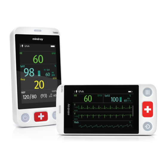
Page 30: Display Screen
Touch Screen Display General Product Description 2.7.1 Display Screen The main screen displays patient parameters and waveforms. A typical display screen of TM80/TM70 is shown below. TM80 TM70 2 - 8 TM80/TM70 Telemetry Monitor Operator’s Manual... - Page 31 [Patient Info] menu. Mindray Patient Area Network (herein abbreviated as MPAN) indicator ◆ indicates that the TM80/TM70 is not paired with the BP10 or one TM80/ TM70 is not connected to another TM80/TM70 for configuration transfer. ◆ indicates that the TM80/TM70 is paired with the BP10 successfully or configuration transfer of the TM80/TM70 is in progress.
-
Page 32: On-Screen Keyboard
Setup menu for the corresponding parameter/waveform. For details about the touch screen operations, refer to "Basic Operations" on page 3 - 2.7.2 On-Screen Keyboard The TM80/TM70 uses an on-screen keyboard to enter alphanumeric information, such as the device name and passwords. 2.7.2.1 Alphabetic Keyboard Alphabetic buttons: tap to input the desired alphabetic text. - Page 33 Accept button: tap to save the settings and exit the keyboard. Space button: tap to input a space. Alphabetic switch button: tap to switch to the alphabetic layout. More punctuation buttons: tap to display the punctuation keyboard, as shown below. TM80/TM70 Telemetry Monitor Operator’s Manual 2 - 11...
- Page 34 Touch Screen Display General Product Description 2 - 12 TM80/TM70 Telemetry Monitor Operator’s Manual...
-
Page 35: Getting Started
Getting Started Unpacking and Checking..................3-2 Environmental Requirements ................3-3 Connecting the ECG Leadwire ................3-4 Installing the Batteries ...................3-5 Powering On the Unit.....................3-8 Understanding Touch Gestures ................3-9 Basic Operations.......................3-10 Using the Pouch .......................3-14 TM80/TM70 Telemetry Monitor Operator’s Manual 3 - 1... -
Page 36: Unpacking And Checking
The network shall be installed by Mindray authorized personnel. • The software equipment copyright is solely owned by Mindray. No orga- nization or individual shall resort to altering, copying, or exchanging it or to any other infringement on it in any form or by any means without due permission. -
Page 37: Environmental Requirements
In this case, never start the system before the condensation disappears. WARNING • Make sure that the device operating environment meets the specifica- tions. Otherwise unexpected consequences, e.g. damage to the device, could result. TM80/TM70 Telemetry Monitor Operator’s Manual 3 - 3... -
Page 38: Connecting The Ecg Leadwire
The system transmits data through a wireless connection. External radio frequency interference may result in occasionally data dropout. Contact Mindray for any questions regarding the electromagnetic environment. Connecting the ECG Leadwire Align the ECG leadwire plug with the ECG connector as indicated by the arrow in the following figure. -
Page 39: Installing The Batteries
◆ Wireless signal strength ◆ Water resistance • Do not use the ECG leadwire to move or lift the TM80/TM70. This may cause the device to fall, which may damage the equipment or injure the patient. NOTE • Insert the SpO... -
Page 40: Installing The Lithium-Ion Rechargeable Battery
Align the hook on the upper part of the lithium-ion battery pack with the slot on the battery compartment, as indicated by the enlarged figure below. Press down the battery pack until it is installed firmly, as indicated by the arrow in the following figure. 3 - 6 TM80/TM70 Telemetry Monitor Operator’s Manual... -
Page 41: Installing The Aa Batteries
Getting Started Installing the Batteries The TM80/TM70 is automatically powered on after the battery is installed. 3.4.2 Installing the AA Batteries To install the AA batteries: Make sure the battery compartment is empty. Insert three 1.5V alkaline AA batteries according to the diagram in the bottom of the battery frame as shown in the images below. -
Page 42: Powering On The Unit
Upon powering up, there are two situations: ■ If the TM80/TM70 is turned on at first time, the device will request you to configure first time startup. ■ If the TM80/TM70 is turned on next time, the device will prompt whether it is a new patient. -
Page 43: Understanding Touch Gestures
Contact your service personnel or Mindray. Understanding Touch Gestures Before using the TM80/TM70, understand the supported touch screen gestures: Gesture Description Briefly touch the surface with your fingertip to select a target. -
Page 44: Basic Operations
This section describes the basic operations for the TM80/TM70. WARNING • Patients should be instructed not to interact with the display of the device and to not open the battery compartment while the TM80/TM70 is in use. 3.7.1 Understanding the Screen Display Orientation The TM80/TM70 supports both the portrait and landscape display orientations. -
Page 45: Switching The Screen Display Orientation
6 - 9 for details. You can customize the most frequently used functions to the quick keys. For details about setting the quick keys, refer to "Quick Keys Menu" on page 13 - 6. TM80/TM70 Telemetry Monitor Operator’s Manual 3 - 11... -
Page 46: Entering The Main Menu
Drag to right to enable the switch; drag to left to disable the switch. Switch exits the current menu and return to the previous menu or the main screen, and saves any modified settings. 3 - 12 TM80/TM70 Telemetry Monitor Operator’s Manual... -
Page 47: Turning The Display Off
For details about configuring the time for Display Auto Off, refer to "Configuring the General Menu" on page 13 - 2. NOTE • While the display is off, the TM80/TM70 enters the power saving mode, and does not provide audio and visual alarms. 3.7.7 Turning the Display On If the screen is off, press the key to turn the display on. -
Page 48: Unlocking The Screen In View Only Mode
The TM80/TM70 is not intended for direct contact with the patient’s skin. During normal use, the TM80/TM70 should be worn over clothing, in a pocket, or in a pouch. The water- proof pouch with clear front is an appropriate means for holding the TM80/TM70. Both disposable and reusable pouches specified in this manual can be used for the TM80/ TM70. - Page 49 Wearing the reusable pouch Wearing the disposable pouch For more information on using the pouch, refer to Pouch Instructions for Use (P/N 046- 007058-00). TM80/TM70 Telemetry Monitor Operator’s Manual 3 - 15...
- Page 50 Be careful about the placement of the straps, as the straps could present a strangulation hazard. NOTE • The pouch is used only for the TM80/TM70. The pouch cannot be used for carrying other personal devices, such as a mobile phone. 3 - 16 TM80/TM70 Telemetry Monitor Operator’s Manual...
-
Page 51: User Configurations
User Configurations Introduction.......................4-2 Configuring the Display..................4-2 Configuring the Audio Volume................4-4 TM80/TM70 Telemetry Monitor Operator’s Manual 4 - 1... -
Page 52: Introduction
Therefore, these parameters will be displayed in the exact order of the [Display Setup] menu, provided the sensor is attached and monitoring data. 4.2.4 Configuring the Portrait Display To configure the portrait display, follow this procedure: 4 - 2 TM80/TM70 Telemetry Monitor Operator’s Manual... -
Page 53: Understanding Landscape Orientation Display Rules
Three options display: [2], [3], and [4]. Tap an option to set the row numbers. The selected option displays to the right of [Rows]. Tap [Landscape Order] to enter the [Landscape Order] menu. TM80/TM70 Telemetry Monitor Operator’s Manual 4 - 3... -
Page 54: Configuring The Display Brightness
• The minimum value for the alarm volume depends on the minimum alarm volume, refer to "Configuring the Alarms Menu" on page 13 - 4 for details. 4 - 4 TM80/TM70 Telemetry Monitor Operator’s Manual... - Page 55 Patient Management Introduction.......................5-2 Admitting a Patient ....................5-2 Changing Patient Information ................5-2 Changing Paced Status..................5-3 Exiting the Standby Mode ..................5-4 Discharging the Patient ..................5-4 TM80/TM70 Telemetry Monitor Operator’s Manual 5 - 1...
-
Page 56: Patient Management
• When the device is connected to the CMS, the patient category at the CMS is updated if the patient category is changed at the TM80/TM70, and vice versa. Refer to the BeneVision Central Monitoring System Opera- tor’s Manual (P/N 046-007960-00) for details. -
Page 57: Changing Paced Status
Removes all patient data from the screen and displays [Standby] on the screen. ■ The screen display automatically turns off after the device enters the Standby mode for 30 seconds. ■ CMS is notified. TM80/TM70 Telemetry Monitor Operator’s Manual 5 - 3... -
Page 58: Exiting The Standby Mode
The TM80/TM70 notifies the CMS of returning to the Monitoring mode. Discharging the Patient When the TM80/TM70 is connected to the CMS, discharging the patient will stop moni- toring at the TM80/TM70 and CMS. After discharging the patient, the patient’s configuration is cleared at the TM80/TM70. -
Page 59: Restarting The Tm80/Tm70
Select [Yes] to clear the current patient’s configuration and start monitoring by applying the user configuration. If the TM80/TM70 does not save the user configuration, it will apply the default departmental settings sent by the CMS for the new patient. - Page 60 Discharging the Patient Patient Management This page intentionally left blank. 5 - 6 TM80/TM70 Telemetry Monitor Operator’s Manual...
-
Page 61: Alarms
Alarms Introduction.......................6-2 Alarm Categories......................6-3 Alarm Levels.......................6-3 Alarm Indicators .......................6-4 Viewing Alarm List....................6-6 Resetting Alarms ......................6-9 TM80/TM70 Telemetry Monitor Operator’s Manual 6 - 1... -
Page 62: Introduction
Alarms, triggered by abnormal vital signs or technical problems, are visually and audibly indicated to the user when the display is on. For the full list of alarm messages displayed at the TM80/TM70, refer to "Troubleshoot- ing" on page 15 - 1. -
Page 63: Alarm Categories
Technical alarms, also called system status alarms, are triggered by a device malfunction or a patient data distortion due to improper operation or mechanical problems. Apart from the physiological and technical alarm messages, the TM80/TM70 will show some messages telling the system status. Alarm Levels The alarms can be classified into three severity levels: high level, medium level and low level. -
Page 64: Alarm Indicators
When the display is off, the user must activate the screen to view any local alarms. 6.5.1 Alarm Light If an alarm occurs, the alarm light on the TM80/TM70 flashes. The color and flashing fre- quency correspond to the alarm level as follows: ■ the lamp quickly flashes red. -
Page 65: Flashing Numeric
• When multiple alarms of different levels occur simultaneously, the TM80/TM70 selects the alarm of the highest level to light the alarm light and sound alarms accordingly, while all the alarm messages scroll in the message area on the top of the screen. -
Page 66: Alarm Status Symbols
Viewing Alarm List Alarms 6.5.5 Alarm Status Symbols The TM80/TM70 still uses the following symbols indicating the alarm status: ■ : indicates that all the alarms are paused. ■ : indicates the technical alarm audio is turned off. ■ : indicates the alarm system is reset. -
Page 67: Initiating Auto Alarm Limits
When auto limits are selected, the TM80/TM70 calculates safe auto limits based on the latest measured values. To get accu- rate auto alarm limits, you need to collect a set of measured vital signs as a baseline. -
Page 68: Restoring The Default Alarm Settings
For technical alarms, alarm sounds are paused, but the alarm lamp and alarm messages remain presented. ■ The remaining alarm pause time is displayed in the message area. ■ The alarm pause symbol is displayed in the upper right corner of the main screen. 6 - 8 TM80/TM70 Telemetry Monitor Operator’s Manual... -
Page 69: Resetting Alarms
You can acknowledge the on-going alarms by resetting the alarms. After being reset, the alarm reset symbol is displayed in the message area. When an alarm occurs, follow this procedure to reset the TM80/TM70’s alarm system. ■ Press the key to enter the main menu, and then tap [Alarm Reset] from the [Commands] section. -
Page 70: Resetting Technical Alarms
√ markwill appear before the alarm message. For details about the indications of technical alarms when the alarm system is reset, refer to "Technical Alarm Messages at the TM80/TM70" on page 15 - 5. 6.10... - Page 71 Monitoring ECG Introduction.......................7-2 Safety..........................7-2 Preparation for Monitoring ECG .................7-3 Changing the ECG Settings ..................7-12 Configuring the HR Alarm Source..............7-16 Understanding the ECG Display .................7-17 ST Monitoring......................7-18 QT/QTc Interval Monitoring..................7-21 Arrhythmia Monitoring..................7-24 Relearning........................7-34 TM80/TM70 Telemetry Monitor Operator’s Manual 7 - 1...
-
Page 72: Introduction
QT/QTc measurements. Operations such as configuring QRS threshold, adjusting ST point/ISO point/J point, set- ting ST template/QT template are performed at the CentralStation. For details about these operations, refer to Chapter 12 Monitoring with the TM80/TM70 at the CMS. Safety WARNING •... -
Page 73: Preparation For Monitoring Ecg
If an electrode is placed over a large muscle such as the pectorals, the device may detect this additional mus- cle activity and could lead to false arrhythmia calls. TM80/TM70 Telemetry Monitor Operator’s Manual 7 - 3... - Page 74 CAUTION • Route leadwires neatly. Ensure leadwires are kept away from patient’s neck to avoid strangulation. Keep floors and walkways free of cables to reduce risk to hospital personnel, patients and visitors. 7 - 4 TM80/TM70 Telemetry Monitor Operator’s Manual...
-
Page 75: Setting Ecg Lead Labeling
ECG tracing, the monitor may have some difficulty in identifying the appropriate waves. On some patients, electrode placement and/or the viewed ECG lead may need to be adjusted in order to obtain a significant R wave. TM80/TM70 Telemetry Monitor Operator’s Manual 7 - 5... - Page 76 A 5-wire lead set can monitor seven ECG vectors (I, II, III, aVR, aVL, aVF, and V) simultane- ously. The recommended 5-wire lead placement is as follows: 5-wire lead placement (IEC) 5-wire lead placement (AHA) 7 - 6 TM80/TM70 Telemetry Monitor Operator’s Manual...
- Page 77 The positions of Va (Ca) and Vb (Cb) can also be placed at a proper position according to the clinician’s needs. Electrode Placement RA (white) R (red) Under the patient’s right clavicle, at the mid-clavicular line within the rib cage frame. TM80/TM70 Telemetry Monitor Operator’s Manual 7 - 7...
- Page 78 In the fifth intercostal space, anterior axillary line. V6 (brown) C6 (white) In the fifth intercostal space, mid-axillary line. 7.3.4.4 Lead Placement: Pacemaker Patients The recommended lead placement for monitoring a pacemaker patient is as follows. 7 - 8 TM80/TM70 Telemetry Monitor Operator’s Manual...
- Page 79 5-wire Lead Placement for a Pacemaker Patient (IEC) (AHA) Pacemaker RA (R) LA (L) V6 (C6) V5 (C5) V1 (C1) V4 (C4) LL (F) RL (N) V2 (C2) V3 (C3) 6-wire Lead Placement for a Pacemaker Patient (AHA)/(IEC) TM80/TM70 Telemetry Monitor Operator’s Manual 7 - 9...
-
Page 80: Checking The Lead Placement
In the main menu, tap [Lead Placement]. 7.3.5.2 Understanding the Lead Placement Instructions The [Lead Placement] window indicates the lead status. Information bar Lead on indicator Lead off indicator Example lead placement window 7 - 10 TM80/TM70 Telemetry Monitor Operator’s Manual... -
Page 81: Checking The Paced Status
"Changing Paced Status" on page 5 - 3. ■ When [Paced] is set to [Yes] at the TM80/TM70, if the pacer pulse is detected, the symbol displays in the waveform area of the CMS’ screen, and the pace pulse marks will display on the ECG waveform both at the TM80/TM70 and CMS. -
Page 82: Changing The Ecg Settings
• In order to minimize the possibility of interference, place electrodes, leadwires and TM80/TM70 as far away from the pacemaker as possible. NOTE • When [Paced] is set to [Yes], the system does not detect PVC-related arrhythmia (including PVCs) resulting from pacemaker but still analyzes the normal QRS complex. -
Page 83: Configuring The Ecg Setup
Use when ST monitoring is applied. Color Selects the ECG waveform color. 16 colors The default color is green. The factory default settings are in bold. to exit the [ECG] menu. TM80/TM70 Telemetry Monitor Operator’s Manual 7 - 13... -
Page 84: Ecg Leadwire Types
This configuration will be applied for all ECG waveform size. Speed Selects the waveform sweep speed. 6.25 mm/s, 12.5 mm/s, 25 mm/s The factory default settings are in bold. to exit the [ECG] menu. 7 - 14 TM80/TM70 Telemetry Monitor Operator’s Manual... -
Page 85: Configuring The Pacer
The [Waveform Size] section of the [ECG] menu lists all available leads. You can select the desired ECG lead to set the waveform size. For details about the waveform size set- ting, refer to "Configuring the Pacer" on page 7 - 15. TM80/TM70 Telemetry Monitor Operator’s Manual 7 - 15... -
Page 86: Configuring Ecg Alarm Settings
Configuring the HR Alarm Source In most cases, the HR and PR numerics are identical. In order to avoid simultaneous alarms on HR and PR, the TM80/TM70 uses either HR or PR as its active alarm source. To change the alarm source: On the main screen, tap the HR digital area or ECG waveform area to enter the [ECG] menu. -
Page 87: Understanding The Ecg Display
Understanding the ECG Display ◆ [Auto]: the TM80/TM70 will use the heart rate from the ECG measurements as the alarm source whenever a valid heart rate is available. If the heart rate becomes unavailable, for example the ECG module becomes disconnected, the TM80/TM70 will automatically switch to PR as the alarm source.
Need help?
Do you have a question about the TM70 and is the answer not in the manual?
Questions and answers