Mindray BeneView T1 Operator's Manual
Transport patient monitor / module
Hide thumbs
Also See for BeneView T1:
- Service manual (104 pages) ,
- Quick reference manual (28 pages) ,
- Operator's manual (286 pages)
Table of Contents
Advertisement
Quick Links
Advertisement
Table of Contents
Troubleshooting

Related Manuals for Mindray BeneView T1


Summary of Contents for Mindray BeneView T1
- Page 1 T1 Patient Monitor Operator’s Manual...
- Page 3 SHENZHEN MINDRAY BIO-MEDICAL ELECTRONICS CO., LTD. (hereinafter called Mindray) owns the intellectual property rights to this Mindray product and this manual. This manual may refer to information protected by copyrights or patents and does not convey any license under the patent rights or copyright of Mindray, or of others.
- Page 4 Contents of this manual are subject to changes without prior notice. All information contained in this manual is believed to be correct. Mindray is not be liable for errors contained herein nor for incidental or consequential damages in connection with the furnishing, performance, or use of this manual.
- Page 5 Mindray shall not have any responsibility in the event of loss or damage in transit Exemptions Mindray's obligation or liability under this warranty does not include any transportation or other charges or liability for direct, indirect or consequential damages or delay resulting from the improper use or application of the product or the use of parts or accessories not approved by Mindray or repairs by people other than Mindray authorized personnel.
- Page 6 Upon request, Mindray provides circuit diagrams, component part lists, descriptions, calibration instructions, or other information which assist the user’s appropriately qualified technical personnel to repair those parts of the equipment which are designated by Mindray DS USA, Inc. as repairable. T1 Patient Monitor Operator’s Manual...
- Page 7 Company Contact Manufacturer: Shenzhen Mindray Bio-Medical Electronics Co., Ltd. Address: Mindray Building, Keji 12th Road South,Hi-tech industrial park, Nanshan, Shenzhen 518057,P.R.China Website: www.mindray.com E-mail Address: service@mindray.com.cn Tel: +86 755 81888998 Fax: +86 755 26582680 Distributor: Mindray DS USA, Inc. Address:...
- Page 8 This manual is based on the maximum configuration and therefore some contents may not apply to your product. If you have any questions, please contact Mindray. This manual is an integral part of the product. It should always be kept close to the equipment so that it can be conveniently referenced when needed.
-
Page 9: Table Of Contents
Contents 1 Safety ....................................1-1 1.1 Safety Information ......................................1-1 1.1.1 Warnings ......................................1-2 1.1.2 Cautions ....................................... 1-3 1.1.3 Notes ........................................1-3 1.2 Equipment Symbols ....................................... 1-4 2 The Basics ................................... 2-1 2.1 Monitor Description ....................................... 2-1 2.1.1 Intended Use ...................................... 2-1 2.1.2 Equipment Features .................................. - Page 10 3.10.1 Switching the Parameters On/Off ............................3-10 3.10.2 Accessing the Parameters Menu .............................3-10 3.11 Operating Modes .......................................3-10 3.11.1 Monitoring Mode ..................................3-10 3.11.2 Night Mode .....................................3-11 3.11.3 Privacy Mode....................................3-11 3.11.4 Outdoor Mode ....................................3-12 3.11.5 Module Mode ....................................3-12 3.11.6 Standby Mode ....................................3-14 4 Managing Patients ................................4-1 4.1 Admitting a Patient ......................................
- Page 11 6.4 Understanding the Big Numerics Screen ............................... 6-5 6.5 Viewing Minitrends (Only Available with the External Display) ..................... 6-5 6.5.1 Having a Split-Screen View of Minitrends ..........................6-6 6.5.2 Setting Minitrends .................................... 6-7 6.6 Viewing OxyCRG (only available with the external display) ......................6-7 6.7 Viewing Other Patients (Only Available with the External Display) ....................
- Page 12 8.3.1 Preparing the Patient and Placing the Electrodes ........................ 8-2 8.3.2 Choosing AHA or IEC Lead Placement ............................8-2 8.3.3 ECG Lead Placements ..................................8-3 8.3.4 Checking Paced Status ..................................8-4 8.4 Understanding the ECG Display ................................8-5 8.5 Changing ECG Settings ....................................8-6 8.5.1 Accessing ECG Menus ..................................
- Page 13 8.10.1 Setting ECG Waveform Sequence ............................8-24 8.10.2 Extending the rhythm lead waveform area ........................8-24 8.11 Resting 12-Lead ECG Analysis ................................8-25 8.11.1 Accessing the 12-Lead Screen ..............................8-25 8.11.2 Entering Patient Information ..............................8-25 8.11.3 12-Lead Setup ....................................8-26 8.11.4 Resting 12-lead ECG Analysis ..............................8-28 8.11.5 12-lead ECG Report ..................................8-29 8.12 Troubleshooting ......................................8-30 9 Monitoring Respiration (Resp) ............................
- Page 14 11.5.9 Setting the Alarm Level for SpO2 Sensor Off Alarm ......................11-5 11.5.10 Setting the SpO2 Tone Mode ..............................11-5 11.6 Measurement Limitations ..................................11-6 11.7 Masimo Information ....................................11-7 11.8 Nellcor Information ....................................11-7 11.9 Troubleshooting ......................................11-8 12 Monitoring NIBP ................................12-1 12.1 Introduction .........................................12-1 12.2 Safety ..........................................12-2 12.3 Measurement Limitations ..................................12-2 12.4 Measurement Methods ....................................12-3...
- Page 15 14.6.4 Setting Up the IBP Wave ................................14-5 14.6.5 Setting the Pressure Unit ................................14-5 14.6.6 Enabling PPV Measurement and Setting PPV Source .....................14-5 14.7 Overlapping IBP Waveforms ...................................14-6 14.8 Measuring PAWP (Only Available with the External Display) .....................14-7 14.8.1 Preparing to Measure PAWP ..............................14-8 14.8.2 Setting Up the PAWP Measurement ............................14-9 14.8.3 Understanding the PAWP Setup Menu ..........................14-9 14.9 Troubleshooting ......................................
- Page 16 17 Calculations (Only Available with the External Display) .................... 17-1 17.1 Introduction .........................................17-1 17.2 Dose Calculations .......................................17-2 17.2.1 Performing Calculations ................................17-2 17.2.2 Selecting the Proper Drug Unit ...............................17-2 17.2.3 Titration Table ....................................17-3 17.2.4 Drug Calculation Formulas ...............................17-3 17.3 Oxygenation Calculations ..................................17-3 17.3.1 Performing Calculations ................................17-3 17.3.2 Entered Parameters ..................................17-4 17.3.3 Calculated Parameters and Formulas ...........................17-4...
- Page 17 19.4.1 Data Export System ..................................19-2 19.4.2 Transferring Data by Different Means ...........................19-2 19.5 Network Setup ......................................19-3 19.5.1 Setting the Network Type ................................19-3 19.5.2 Wireless Network Connection ..............................19-3 19.5.3 Viewing the MAC Address .................................19-6 19.5.4 Enabling the Data Encryption ..............................19-6 19.5.5 Settting DNS ....................................19-6 19.5.6 Certificates Maintenance ................................19-7 19.5.7 Connecting the Monitor to the CMS .............................19-7 19.5.8 Setting the Central Stations..............................19-8...
- Page 18 22.6 CO Leakage Test ......................................22-4 22.7 Calibrating the Touchscreen ...................................22-5 23 Accessories..................................23-1 23.1 ECG Accessories ......................................23-1 23.2 SpO Accessories ......................................23-3 23.3 NIBP Accessories ......................................23-4 23.4 Temp Accessories .......................................23-5 23.5 IBP Accessories ......................................23-6 23.6 CO Accessories ......................................23-6 23.7 Mount and Mounting Accessories ...............................23-7 23.8 Miscellaneous Accessories ..................................23-7 A Product Specifications ..............................
-
Page 19: Safety
Safety 1.1 Safety Information WARNING Indicates a potential hazard or unsafe practice that, if not avoided, could result in death or serious injury. CAUTION Indicates a potential hazard or unsafe practice that, if not avoided, could result in minor personal injury or product/property damage. -
Page 20: Warnings
Do not open the equipment housings. All servicing and future upgrades must be carried out by the personnel trained and authorized by Mindray only. Do not come into contact with patients during defibrillation. Otherwise serious injury or death could result. -
Page 21: Cautions
Disposable accessories are not designed to be reused. Reuse may cause a risk of contamination and affect the measurement accuracy. Contact the Mindray service personnel for replacements if you find the housing is broken. 1.1.3 Notes NOTES ... -
Page 22: Equipment Symbols
1.2 Equipment Symbols Some symbols may not appear on your equipment. ON/OFF for a part of equipment Direct current Battery indicator Network connector Multifunctional connector Serial number Unlocking Equipotentiality VGA connector Direction and angle of rotation Lock; tighten Alternating current Date of Manufacture Symbol for “MANUFACTURER”... -
Page 23: The Basics
ST Segment analysis of Mindray ECG algorithm is intended for adult patients only. The monitor is to be used in healthcare facilities by clinical professionals or under their guidance. It should only be used by persons who have received adequate training in its use. It is not intended for helicopter transport, hospital ambulance, or home use. -
Page 24: Equipment Features
As a stand-alone patient monitor, or As a multi-parameter module (MPM) for the Mindray Passport 17M and Passport 12M patient monitors, hereafter referred to as “the host monitor”. In this manual, the T1 is generally referred to as “the monitor” except in the situation describing its use with a host monitor, where it is referred to as “the T1”... -
Page 25: Equipment Description
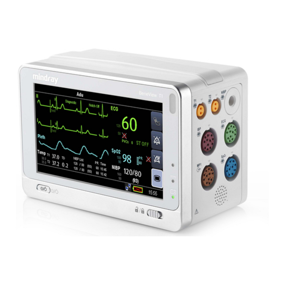
2.2 Equipment Description 2.2.1 Main Unit 2.2.1.1 Front View Alarm lamp When a physiological alarm or technical alarm occurs, this lamp flashes as defined below. High level alarms: the lamp quickly flashes red. Medium level alarms: the lamp slowly flashes yellow. ... - Page 26 Lock/unlock switch When the T1 is not connected with the external display, sliding this switch to the right locks/unlocks the touch screen. When the T1 is connected to the external display, sliding this switch to the right switches screen display between the T1 and the external display.
- Page 27 2.2.1.3 Right View Temp probe 1 connector Temp probe 2 connector IBP cable connector Multifunctional connector: outputs analog ECG, IBP and defibrillation synchronization signals. NIBP cuff connector ECG cable connector cable connector Speaker 2.2.1.4 Bottom View Latch: locks the T1 when the T1 is in use with the host monitor, the T1 docking station, or the T1 handle. Pressing here releases the T1 so that you can remove it from the host monitor, the T1 docking station, or the T1 handle.
-
Page 28: T1 Handle
2.2.2 T1 handle The T1 handle is used to connect a T1 and an external parameter module as well as providing bed rail mounting capability. It can also be connected to the T1 docking station. 2.2.2.1 Left View Release button: pressing this button releases the T1 handle from the T1 docking station. T1 handle multi-pin connector 1: connects the T1 handle and T1 docking station. -
Page 29: T1 Docking Station
2.2.3 T1 Docking Station The T1 docking station is used to connect the T1 or T1 handle to provide power, charge the installed battery, and support connection to an external display, USB drive, network cables, and the Passport 12M/17M patient monitors. 2.2.3.1 Left View Symbol: indicates the direction and angle that the T1 docking station can rotate when the T1 docking station is fixed onto a transverse or a vertical rod. -
Page 30: External Parameter Modules
2.2.3.3 Rear View AC power input Equipotential grounding terminal When using the monitor together with other devices, connect their equipotential grounding terminals together to eliminate the potential differences between them. VGA connector: connects the external display External device connector: connects the T1 to the host monitor through a cable. USB connector: connects USB devices, including the USB drive, mouse and keyboard. -
Page 31: Installation
2.3 Installation The T1 handle and T1 docking station are part of the equipment. Use only the specified T1 handle and T1 docking station. 2.3.1 T1 in Use with the T1 Handle You can install the T1 and an external parameter module, if needed, to the T1 handle as indicated below: You hear a click when the T1 or the external module is pushed into place. -
Page 32: T1 Handle In Use With The T1 Docking Station
CAUTION To prevent the T1 from falling out, do not press the release button while transporting the T1 with the T1 handle. 2.3.2 T1 Handle in Use with the T1 Docking Station The T1 handle can be installed into the T1 docking station as indicated below: You hear a click when the T1 handle is pushed into place. -
Page 33: T1 In Use With The T1 Docking Station
2.3.3 T1 in Use with the T1 Docking Station You can also install the T1 directly to the T1 docking station as indicated below: You hear a click when the T1 is pushed into place. To remove the T1 from the T1 docking station: Press and hold the latch at the bottom of the T1. -
Page 34: Display Screen
2.4 Display Screen This monitor uses a high-resolution TFT LCD to display patient parameters and waveforms. A typical display screen is shown below. Alarm Symbols Patient Information/Technical Alarm Area This area shows the patient information such as department, bed number, patient name, patient category and paced status. - Page 35 QuickKeys Area This area contains QuickKeys that provides quick access to functions. Start or stop NIBP measurements Reset the alarms Enter/Exit the alarm paused state Enter the main menu if no menu is currently displayed. If a menu is didsplayed on the screen, pressing it closes that menu.
- Page 36 FOR YOUR NOTES 2-14 T1 Patient Monitor Operator’s Manual...
-
Page 37: Basic Operations
NOTE The software equipment copyright is solely owned by Mindray. No organization or individual shall resort to modifying, copying, or exchanging it or to any other infringement on it in any form or by any means without due permission. -
Page 38: Unpacking And Checking
Mindray. If the packing case is intact, open the package and remove the equipment and accessories carefully. Check all materials against the packing list and check for any mechanical damage. Contact Mindray in case of any problems. CAUTION ... -
Page 39: Getting Started
3.2 Getting Started 3.2.1 Connecting to Power Source Using DC Power Adapter To connect to the AC mains using the DC power adapter, connect one end of the power cord of the adapter with the DC power input on the equipment’s back panel and the other end with a wall AC mains outlet. Using the T1 Docking Station To connect to the AC power using the T1 docking station: Install the monitor to the T1 docking station as described in section 2.3.3 T1 in Use with the T1 Docking Station. -
Page 40: Turning Power On
WARNING Do not use the monitor on a patient if you suspect it is not working properly, or if it is mechanically damaged. Contact your service personnel or Mindray. NOTE Carefully check if the system performs the self-test as described above. Contact your service personnel or Mindray if the self-test is abnormal. -
Page 41: Turning Off The Monitor
3.3 Turning Off the Monitor Before turning off the monitor: Ensure that the monitoring of the patient has been completed. Disconnect the cables and sensors from the patient. Make sure to save or clear the patient monitoring data as required. Press and hold the power on/off switch to turn off the monitor. -
Page 42: Using The On-Screen Keyboard
3.5 Using the On-Screen Keyboard The onscreen keyboard enables you to enter information. Use the key to delete the previously entered character. Use the key to toggle between uppercase and lowercase letters. Select to confirm what you have entered and close the onscreen keyboard. ... -
Page 43: Using The Mouse And Keyboard
CAUTION Only use the display specified by Mindray. Using an unspecified display may result in unknown problems. 3.7 Using the Mouse and Keyboard When connected to the external display, the T1 can connect a mouse and a keyboard through the USB connector of the T1 docking station. -
Page 44: Changing General Settings
3.9 Changing General Settings 3.9.1 Setting Up a Monitor To install a monitor or change its location: Select [Main Menu] → [Maintenance >>]→[User Maintenance >>]→enter the required password. In the [User Maintenance] menu, enter the [Monitor Name], [Department] and [Bed No.]. You can set [Changing Bed No.] to: ... -
Page 45: Setting The Docking Station
3.9.4 Setting the Docking Station To make sure that the T1 can be used with the docking station for the patient transfer, you need to configure the docking station on the T1. To configure the docking station, select [Main Menu]→[Maintenance >>]→[User Maintenance >>]→enter the required password→[Others >>]→[Dock Setup >>]. -
Page 46: Setting Parameters
Setting the IP for CMS The IP of the CMS defines the IP address of the CMS to which the T1 is connected. The T1 can only be connected to the specified CMS. The IP address of the current CMS is shown in the prompt message area. You can select this area to pop up the [Central Station IP] menu. -
Page 47: Night Mode
3.11.2 Night Mode To avoid disturbing the patient, the Night mode may be used. To activate the Night mode: Select [Main Menu]→[Screen Setup >>]→[Night Mode >>]. In the pop-up menu, set the desired brightness, alarm volume, QRS volume, key volume, NIBP end tone, and whether to stop NIBP measurements or not. -
Page 48: Outdoor Mode
WARNING In the Privacy mode, all audible alarms are suppressed and the alarm light is deactivated at the monitor. Alarms sound only at the CMS. NOTE The Privacy mode can be used only when the monitor is connected to a CMS. 3.11.4 Outdoor Mode The Outdoor mode is intended for transporting patients in bright ambient light conditions. - Page 49 Insert the T1 in the module rack of the host monitor To use the T1 with the host monitor, insert the T1 into the host monitor’s internal module rack or satellite module rack. Firmly push the T1 until you hear that the clip engages the module rack. To ensure that the T1 is properly connected, try to pull the T1 outward.
-
Page 50: Standby Mode
3.11.6 Standby Mode In the Standby mode, you can temporarily stop patient monitoring without turning off the monitor. To enter the Standby mode: Select [Main Menu]→[Standby]. Select [Yes] in the pop-up menu. 3-14 T1 Patient Monitor Operator’s Manual... -
Page 51: Managing Patients
Managing Patients 4.1 Admitting a Patient The monitor displays and stores physiological data in trends as soon as a patient is connected. This allows you to monitor a patient that is not admitted yet. However, it is recommended that you fully admit a patient so that you can clearly identify them on reports and network devices. -
Page 52: Quick Admitting A Patient
4.2 Quick Admitting a Patient Use [Quick Admit] only if you do not have the time or information to fully admit a patient. Complete the rest of the patient demographic details later. To quick admit a patient: Select [Main Menu]→[Patient Setup >>]. Select [Quick Admit]. -
Page 53: Querying From Local Facility
NOTE The option [Obtain Patient Information] is available in the [Patient Setup] menu only when [ADT Query] is set to [On]. When obtaining patient information from the HIS, only patient information is updated onthe monitor. The patient’s physiological data is not changed and the patient is not discharged. 4.5 Querying from Local Facility You can query the patient information from either the local facility or all networked facilities. -
Page 54: Discharging A Patient
You can also input the patient’s visit number in the [Patient Demographics] menu, but the [Visit Number] option needs to be enabled. To display the [Visit Number] option in the [Patient Demographics] menu: Select [Main Menu]→[Maintenance >>]→[User Maintenance >>]→enter the required password. Set [Visit Number] to [On >>]. -
Page 55: Transferring Patient Data Via A Usb Drive
4.9.1 Transferring Patient Data via a USB Drive To transfer patient data to a USB drive: Select [Others >>] from the [User Maintenance] menu. In the pop-up menu, set [Data Transfer Method] to [USB Drive]. You can also set [Transferred Data Length]. The default is [4 h]. 4.9.1.1 Transferring Data from the Monitor to a USB Drive To transfer data from the monitor to a USB drive: Connect the T1 to the T1 docking station. -
Page 56: Transferring Patient Data Via The T1 To A Host Monitor
CAUTION The USB drive you use may be write-protected. In this case, make sure the USB drive is in read/write mode. Do not remove the storage medium during the data transfer process. Otherwise, data files may be damaged. ... -
Page 57: Managing Configurations
Managing Configurations 5.1 Introduction When performing continuous patient monitoring, the clinical professional often needs to adjust the monitor’s settings according to the patient’s condition. The collection of all these settings is called a configuration. Allowing you to configure the monitor more efficiently, the monitor provides different sets of configurations to accommodate the varying patient categories and departments. -
Page 58: Accessing The [Manage Configuration] Menu
5.2 Accessing the [Manage Configuration] Menu To access the [Manage Configuration] menu: Select [Main Menu]→[Maintenance >>]→[Manage Configuration >>]. Enter the required password and then select [Ok]. 5.3 Changing Department If the current department configuration is not the one you want to view, you can select [Change Department >>] in the [Manage Configuration] menu and then choose the desired department as shown below. -
Page 59: Setting Default Configuration
5.4 Setting Default Configuration The monitor will load the pre-set default configuration in the following cases: The monitor restarts after being switched off for more than 120 seconds. A patient is admitted. A patient is discharged. Patient data is cleared. -
Page 60: Editing Configurations
5.6 Editing Configurations To edit an existing configuration: Select [Edit Config. >>] in the [Manage Configuration] menu. The pop-up menu shows the existing configurations on the monitor. Selecting [Config. on USB drive >>] will show the existing configurations on the USB drive. -
Page 61: Loading A Configuration
5.9 Loading a Configuration You may make changes to some settings during operation. However, these changes or the pre-selected configuration may not be appropriate for the newly admitted patient. Therefore, the monitor allows you to load a desired configuration to ensure that all the settings are appropriate for your patient. To load a configuration: Select [Load Configuration >>] from the [Main Menu]. - Page 62 FOR YOUR NOTES T1 Patient Monitor Operator’s Manual...
-
Page 63: User Screens
User Screens 6.1 Adjusting the Screen Brightness To adjust the screen brightness: Select the [Main Menu]→[Screen Setup >>]→[Brightness]. Select the appropriate setting for the screen brightness. 1 to 10. 10 is the brightest, and 1 is the dimmest. Auto: Screen brightness will be adjusted automatically. -
Page 64: Configuring Your Screens
To adjust the QRS volume: Select the ECG parameter window →[Others >>], or the SpO parameter window. Select [QRS Volume] or [Beat Vol] and then select the appropriate volume. 0 means off, and 10 is the maximum volume. 6.3 Configuring Your Screens You can configure your monitor’s screens by setting: ... -
Page 65: Changing The T1 Screen Layout
If the external display is connected, you can also choose: ECG 7-Lead Half-Screen if 5-lead or 12-lead ECG is selected Minitrends Screen OxyCRG Screen View Others Screen PAWP Screen 6.3.4 Changing the T1 Screen Layout To change screen layout, select [Main Menu]→[Screens] to enter the [Screens] menu. -
Page 66: Changing Screen Layout On The External Display
WARNING Unallocated parameters in the [Screen Setup] window do not display. However, the monitor can still sound alarms for these parameters. 6.3.5 Changing Screen Layout on the External Display NOTE The keys mentioned in this section refer to the keys on the external display. To change the screen layout on the external display: ... -
Page 67: Understanding The Big Numerics Screen
The ECG parameter and the first ECG waveform always display in the first row. The configurable areas can be classified as Area A, Area B, and Area C. In Area A, you can choose to display the parameters windows and their waveforms (if one exists). Each parameter and the associated waveform are displayed in the same row. -
Page 68: Having A Split-Screen View Of Minitrends
6.5.1 Having a Split-Screen View of Minitrends You can split the normal screen so that the left hand side continuously shows graphic minitrends beside waveforms as shown in the figure below. To have a split-screen view of minitrends, you can select [Main Menu]→[Screen Setup >>]→[Screen Layout >>]→ [Choose Screen]→[Minitrends Screen]→... -
Page 69: Setting Minitrends
6.5.2 Setting Minitrends Select the minitrends area. From the pop-up [Minitrend Setup] menu, you can: Select the parameters to be displayed, or Select [Minitrend Length] and then select the appropriate setting. Time 6.6 Viewing OxyCRG (only available with the external display) NOTE ... -
Page 70: Viewing Other Patients (Only Available With The External Display)
The split-screen view covers the lower part of the waveform area and shows HR trend, SpO trend, SpO b trend, RR trend and a compressed waveform (CO wave or Resp wave). At the bottom, there are controls: Event You can enter the [Review] menu by selecting the [Event] button. Trend length list box In the trend length list box, you can select [1 min], [2 min], [4 min], or [8 min]. -
Page 71: Viewing The Care Group Overview Bar
NOTES Monitors using software version prior to 05.17.00 cannot view or be viewed by monitors of software version 05.17.00 or later. Re-set the Care Group if the monitor is moved to a department or different LAN. 6.7.2 Viewing the Care Group Overview Bar The Care Group Overview bar is located at the bottom of the [View Other Patient] window. - Page 72 The [View Other Patient] window covers the lower part of the waveform area and consists of: Information Area: shows the patient information (including department, bed number, patient name, etc.), and network status symbol. View Area: shows physiological waveforms and parameters. You can switch a waveform area to a parameter area by selecting your desired waveform area and then selecting [Switch to Parameter Area], or switch a parameter area to a waveform area by selecting your desired parameter area and then selecting [Switch to Waveform Area].
-
Page 73: Alarms
Alarms Alarms, triggered by an abnormal vital sign or technical issue with the monitor as visually and audibly indicated to the user. WARNING A potential hazard can exist if different alarm presets are used for the same or similar equipment in any single area, e.g. -
Page 74: Alarm Levels
7.2 Alarm Levels The monitor’s alarms can be classified into three seerity categories: high level, medium level and low level. Physiological alarms Technical alarms High level Indicatess that the patient is in a life Indicates a severe device malfunction or an improper operation threatening situation, such as Asystole, which could make it possible that the monitor cannot detect Vfib/Vtac and so forth, and emergency... -
Page 75: Flashing Numeric
Additionally, the alarm message has a different background color which corresponds to the alarm level: High level alarms: Medium level alarms: yellow Low level alarms: yellow You can view the alarm messages by selecting the physiological or technical alarm area. Refer to 2.4 Display Screen for details. -
Page 76: Alarm Status Symbols
7.3.5 Alarm Status Symbols Apart from the aforementioned alarm indicators, the monitor still uses the following symbols telling the alarm status: indicates alarms are paused. indicates alarm is reset. indicates the alarm sound is turned off. indicates individual measurement alarms are turned off or the system is in alarm off status. -
Page 77: Setting The Interval Between Alarm Sounds
7.4.3 Setting the Interval between Alarm Sounds If you choose the ISO pattern, you can change the interval between alarm tones. To change the interval between alarm tones: Select [Main Menu]→[Maintenance >>]→[User Maintenance >>]→enter the required password. Select [Alarm Setup >>] to enter the [Alarm Setup] menu. Select [High Alarm Interval (s)], [Med Alarm Interval (s)] and [Low Alarm Interval (s)] in order and then select the appropriate settings. -
Page 78: Setting The Reminder Tones
.4.5 Setting the Reminder Tones When the reminder tone is switched on and a physiological or technical alarm condition exists, the monitor gives a periodic reminder tone in the following cases: When the alarm volume is set to zero, a high, medium, low, or technical audible alarm indication will be generated at the set reminder interval until the alarm condition is cleared. -
Page 79: Setting Alarm Properties For All Parameters
When a Panorama CMS is used, the [Alarm Setup] menu displays as below: NOTE The On/Off column is only not visible with Panorama CMS. Refer to chapter 8 Monitoring ECG for how to change ST alarm settings, how to change arrhythmia alarm settings, and how to set the threshold for some arrhythmia alarms. - Page 80 To get accurate auto alarm limits, you need to collect a set of measured vital signs as a baseline. Then, in the [Main Menu], select [Alarm Setup >>]→[Parameters]→[Auto Limits] →[Ok]. The monitor will create new alarm limits based on the measured values. Before applying these automatically created alarm limits, confirm if they are appropriate for your patient in the [Alarm Setup Menu].
- Page 81 Low alarm limit High alarm limit Module Parameter Auto alarm limits range Adult/ Adult/ Neonate Neonate pediatric pediatric FAP/ (Dia – 15) or 20 (Diav15) or 80 Adult: 25 to 225 mmHg mmHg (Dia × 0.68+6) (Dia × 0.86+32) IBP-D Pediatric: 25 to 150 P1-P4 mmHg...
-
Page 82: Setting Alarm Delay Time
7.5.3 Setting Alarm Delay Time You can set the alarm delay time for alarms of continuously measured parameters. If the alarm condition is resolved within the delay time, the monitor will not sound the alarm. To set the alarm delay time: Select [Main Menu]→[Maintenance >>]→[User Maintenance >>]. -
Page 83: Setting Recording Length
7.5.5 Setting Recording Length You can change the length of the recorded waveforms. In the [Others] window of the [Alarm Setup] menu, select [Recording Length] and then select [8 s], [16 s] or [32 s]: [8 s]: 4 seconds respectively before and after the alarm or manual event trigger moment. ... -
Page 84: Switching Off All Alarms
7.7 Switching Off All Alarms If [Alarm Pause Time] is set to [Permanent]: the monitor will enter into the alarm off status after the QuickKey is pressed. During the alarm off status: As for physiological alarms: no alarm lamps flash and no alarms are sounded. ... -
Page 85: Latching Alarms
Technical alarms give different alarm indicators when the alarm system is reset: For some technical alarms, including the NIBP-related alarms, a √ appears before the alarm message and appears in the alarm symbol area, indicating that the alarm is acknowledged. The indication of the alarm lamp depends on the alarm light setting. -
Page 86: Testing Alarms
The rules for latching the alarms are: You can separately select [Latching Visual Signal]. Selecting [Latching Audible Signal] simultaneously latches the visual signal. Selecting alarms of lower priority simultaneously latches the alarms of higher priority. The lethal alarms are latched by default. High, medium, and low priority alarms are unlatched by default. NOTE ... -
Page 87: Using Care Group Alarms (Only Available With The External Display)
7.11 Using Care Group Alarms (Only Available with the External Display) NOTE The keys mentioned in this section refer to the keys on the external display. 7.11.1 Care Group Auto Alarms When a Care Group is set up on your monitor, a flashing symbol will appear beside the QuickKeys area if any monitor in your Care Group, which is not currently viewed by your monitor, is alarming. - Page 88 FOR YOUR NOTES 7-16 T1 Patient Monitor Operator’s Manual...
-
Page 89: Monitoring Ecg
This equipment is not intended for direct cardiac application. Use only ECG electrodes and cables specified by Mindray. Make sure the conductive parts of electrodes and associated connectors for applied parts, including the neutral electrode, should not contact any other conductive parts including earth. -
Page 90: Preparing To Monitor Ecg
CAUTION Interference from a non-grounded instrument near the patient and electrosurgery interference can cause problems with the waveform. NOTE After defibrillation, the screen display recovers within 10 seconds if the correct electrodes are used and applied in accordance with the instructions for use. 8.3 Preparing to Monitor ECG 8.3.1 Preparing the Patient and Placing the Electrodes To prepare the patient and place the electrodes:... -
Page 91: Ecg Lead Placements
8.3.3 ECG Lead Placements The electrode placement illustrations in this chapter adopt the AHA standard. 3-Leadwire Electrode Placement Following is an electrode configuration when using 3 leadwires: RA placement: directly below the clavicle and near the right shoulder. LA placement: directly below the clavicle and near the left shoulder. -
Page 92: Checking Paced Status
12-Leadwire Electrode Placement 12-lead ECG uses 10 electrodes, which are placed on the patient’s four limbs and chest. The limb electrodes should be placed on the soft skin and the chest electrodes placed according to the physician’s preference. Lead Placement for Surgical Patients The surgical site should be taken into consideration when placing electrodes on a surgical patient. -
Page 93: Understanding The Ecg Display
WARNING For paced patients, you must set [Paced] to [Yes]. If it is incorrectly set to [No], the monitor could mistake a pace pulse for a QRS and fail to alarm when the ECG signal is too weak. On ventricular paced patients, episodes of Ventricular Tachycardia may not always be detected. -
Page 94: Changing Ecg Settings
8.5 Changing ECG Settings 8.5.1 Accessing ECG Menus By selecting the ECG parameter window or waveform area, you can access the [ECG Setup] menu. 8.5.2 Setting Pacemaker Rate (For Mortara ECG Algorithm only) Some pacemaker pulses can be difficult to reject. When this happens, the pulses are counted as a QRS complex and could result in an incorrect HR and failure to detect some arrhythmias. -
Page 95: Changing The Ecg Filter Settings
8.5.5 Changing the ECG Filter Settings The ECG filter setting defines how ECG waves are smoothed. To change the filter setting, select [Filter] from [ECG Setup] and then select the appropriate setting. [Mon]: Use under normal measurement conditions. [Diag]: Use when diagnostic quality is required. -
Page 96: Setting The Notch Filter
8.5.8 Setting the Notch Filter The notch filter removes the line frequency interference. Only when [Filter] is set to [Diagnostic], the [Notch Filter] is adjustable. To set the notch filter: Select the ECG parameter window or waveform area to enter its setup menu. Then select [Others >>]. Set [Notch Filter] to: ... -
Page 97: Adjusting Qrs Volume
8.5.12 Adjusting QRS Volume QRS sounds are produced based on the alarm source. To adjust the QRS volume, Select [Others >>] from the [ECG Setup] menu. Select [QRS Volume] from the pop-up menu and select the appropriate setting. When a valid SpO measured value is available, the system adjusts the pitch tone of QRS sound based on the SpO value. -
Page 98: About The Defibrillator Synchronization
8.5.14 About the Defibrillator Synchronization A synchronization pulse (100 ms, +5 V) is output through the multifunctional connector each time the monitor detects an R-wave. To use the defibrillator synchronization function, connect the monitor and the defibrillator with a synchronization cable. WARNING ... -
Page 99: Switching St Monitoring On And Off
8.6.1 Switching ST Monitoring On and Off To switch ST monitoring on or off: In the [ECG Setup] menu, select [ST Analysis >>]. Next to the ST Analysis setting, select [On] or [Off]. Reliable ST monitoring cannot be ensured if: ... -
Page 100: Saving The Current St Segment As Reference
Select the ST parameter window or ST segment area to enter the [ST Analysis] menu. 8.6.3 Saving the Current ST Segment as Reference Select [Save Ref.] in the [ST Analysis] menu to save the current segment as a reference. Up to 20 references segment groups can be saved. -
Page 101: Adjusting St Measurement Points
8.6.8 Adjusting ST Measurement Points As shown in the figure below, the ST measured for each beat complex is the vertical difference between two measurement points with the R-wave peak as the baseline for the measurement. R-wave peak J point Difference=ST value ST measurement point Isoelectric point... -
Page 102: Qt/Qtc Interval Monitoring (For Advanced Ecg Algorithm Only)
[J+40 ms], [J+60 ms] or [J+80 ms]. When [J+60/80 ms] is selected, the ST-point will be positioned 80 ms (heart rate 120 bpm or less) or 60 ms (heart rate more than 120 bpm) from the J-point. NOTE Only Advanced ECG algorithm has the function of automatic J point detection. ... -
Page 103: Qt/Qtc Monitoring Limitations
8.7.1 QT/QTc Monitoring Limitations Some conditions may make it difficult to achieve reliable QT monitoring, for example: R-wave amplitudes are too low The presence of frequent ventricular ectopic beats Unstable RR intervals P-waves tending to encroach on the end of the previous T-wave at high heart rates ... -
Page 104: Displaying Qt/Qtc Parameters And Waveform
8.7.3 Displaying QT/QTc Parameters and Waveform To display QT numerics and waveform: Select [Main Menu] →[Screens] to enter the [Screens] window Select the [Screen Setup] tab. 3. Select the parameter area where you want to display the QT parameters and select [QT]. NOTE ... -
Page 105: Changing Qt Settings
The following picture shows the QT view. The current waveform is shown in the upper half in green. The reference waveform is shown below in yellow. The start of QRS complex and the end of the T wave are marked with vertical lines. ... -
Page 106: Changing Qtc Formula
8.7.6 Changing QTc Formula The monitor uses as a default the Hodges correction formula to correct the QT interval for heart rate. To change the QTc formula: Select the QT parameter area or waveform area to enter the [QT Analysis] menu. Set [QTc Formula]. -
Page 107: Understanding The Arrhythmia Events
8.8.1 Understanding the Arrhythmia Events Mortara ECG algorithm Arrhythmia Message Description Category No QRS complex detected within the set time threshold (in absence of Asystole ventricular fibrillation or chaotic signals). Lethal Vfib Ventricular fibrillation occurs and persists for 6 seconds. arrhythmia Ventricular HR is greater or equal to the preset threshold and the number Vtac... - Page 108 Advanced ECG algorithm Arrhythmia message Description Category No QRS detected within the set time threshold in absence of ventricular Asystole fibrillation or chaotic signal. A fibrillatory wave for 6 consecutive seconds. Vfib/Vtac A dominant rhythm of adjacent Vs and a HR > the V-Tac HR limit. Lethal Vtac The consecutive PVCs ≥...
-
Page 109: Changing Arrhythmia Alarm Settings
8.8.2 Changing Arrhythmia Alarm Settings To change arrhythmia alarm settings, select the ECG parameter area or waveform area →[ECG Setup]→ [Arrh. Analysis >>]. In the pop-up menu, you can set the [Alm Lev] to [High], [Med], [Low] or [Message], or switch on lethal arrhythmia analysis alarms only or switch on/off all arrhythmia analysis alarms. -
Page 110: Setting The Extended Arrhythmia (For Advanced Ecg Algorithm Only)
Advanced ECG algorithm Arrh. event Range Default Step Unit PVCs High 1 to 100 /min Asys. Delay 3 to 10 Tachy High 60 to 300 Adult: 120 Pediatric: 160 Neonate: 180 Brady Low 15 to 120 Adult: 50 Pediatric: 75 Neonate: 90 Extreme Tachy 120 to 300... -
Page 111: Ecg Relearning
8.9 ECG Relearning 8.9.1 Initiating an ECG Relearning Manually During ECG monitoring, you may need to initiate an ECG relearning when the patient’s ECG template changes dramatically. A change in the ECG template could result in: Incorrect arrhythmia alarms ... -
Page 112: 12-Lead Ecg Monitoring
8.10 12-Lead ECG Monitoring To access the 12-lead ECG monitoring screen: Refer to section 8.3.3 ECG Lead Placements for placing the electrodes. In the [ECG Setup] menu, select [Others>>] to enter the [Others Setup Menu]. Set [Lead Set] to [12-Lead], set [ECG Display] to [12-Lead]. There are a total of 12 ECG waves and 1 rhythm wave displayed on the screen. -
Page 113: Resting 12-Lead Ecg Analysis
8.11 Resting 12-Lead ECG Analysis The equipment incorporates the Glasgow algorithm, developed by the University of Glasgow, to provide an interpretation of the resting 12-lead ECG in all situations. 8.11.1 Accessing the 12-Lead Screen To access the 12-lead screen: In the [ECG Setup] menu, select [Others>>] to enter the [Other Setup Menu]. Set [Lead Set] to [12-Lead]. -
Page 114: 12-Lead Setup
8.11.3 12-Lead Setup In the 12-lead screen, select [Setup] to enter the [12-Lead Setup] menu to change the settings related to 12-lead ECG analysis. In the [12-Lead Setup] menu, you can also select [Report Setup>>] to set the format and contents of the ECG reports. - Page 115 QTc Formula Hodges, Hodges Selects QTc formula. Bazett, HeartRate Hodges: Fridericia, HeartRate Framingham Bazett: HeartRate Fridericia: ...
-
Page 116: Resting 12-Lead Ecg Analysis
8.11.4 Resting 12-lead ECG Analysis Before 12-lead ECG interpretation, check that all electrodes are correctly connected to the lead wires and the ECG trunk cable is properly connected. Check that patient information is correct. To start analyzing, select the [Analyze] key. The resting 12-lead analysis takes about 10 seconds. During this period, keep the patient still. -
Page 117: 12-Lead Ecg Report
8.11.5 12-lead ECG Report The format and contents of the 12-lead ECG report are configurable. Refer to Report Setup in 8.11.312-Lead Setup for details. The following is a sample of the12-lead ECG report with default configuration. Patient information Time of resting 12-lead ECG analysis Measurements Diagnosis statement Waveform amplitude... -
Page 118: Troubleshooting
8.12 Troubleshooting This section lists the problems that might occur. If you encounter the problems when using the equipment or accessories, check the table below before requesting for services. If the problem persists, contact your service personnel. CAUTION Never try to disassemble the equipment or supplied accessories. There are no internal user-serviceable parts. - Page 119 Symptoms Possible Cause Correction Action No ECG Waveform Gain set too low Set the gain as required. For details, refer to section 8.5.4 Changing ECG Wave Settings. Lead wires and patient cable not fully Check that the leadwires and patient cables are or properly inserted properly connected.
- Page 120 FOR YOUR NOTES 8-32 T1 Patient Monitor Operator’s Manual...
-
Page 121: Monitoring Respiration (Resp)
Monitoring Respiration (Resp) 9.1 Introduction Impedance respiration is measured across the thorax. When the patient is breathing or ventilated, the volume of air changes in the lungs, resulting in impedance changes between the electrodes. Respiration rate (RR) is calculated from these impedance changes, and a respiration waveform appears on the monitor screen. -
Page 122: Placing Resp Electrodes
9.4 Placing Resp Electrodes As the skin is a poor conductor of electricity, preparing the skin is necessary for a good respiration signal. You can refer to the ECG section for how to prepare the skin. For details, refer to section 8.3.1 Preparing the Patient and Placing the Electrodes. -
Page 123: Abdominal Breathing
9.4.3 Abdominal Breathing Some patients with restricted movement breathe mainly abdominally. In these cases, you may need to place the left leg electrode on the left abdomen at the point of maximum abdominal expansion to optimise the respiratory wave. 9.4.4 Lateral Chest Expansion In clinical applications, some patients (especially neonates) expand their chests laterally, causing a negative intrathoracic pressure. -
Page 124: Changing Resp Wave Settings
Use manual detection mode for situations where: The respiration rate and the heart rate are close. Patients have intermittent mandatory ventilation. Respiration is weak. Try repositioning the electrodes to improve the signal. In Auto Detection Mode, if you are monitoring Resp and ECG is switched off, the monitor cannot compare the ECG and Resp rates to detect cardiac overlay. -
Page 125: Setting Alarm Properties
The RR source options and description are shown in the table below. Option Description Auto RR source is automatically selected according to the priority. RR source is from CO measurement. RR source is from impedance respiration measurement. 9.10 Setting Alarm Properties Select [Alarm Setup >>] from the [Resp Setup] menu. - Page 126 FOR YOUR NOTES T1 Patient Monitor Operator’s Manual...
-
Page 127: Monitoring Pr
Monitoring PR 10.1 Introduction The pulse numeric counts the arterial pulsations that result from the mechanical activity of the heart. You can display a pulse from any measured SpO or any arterial pressure (see chapter 14 Monitoring IBP). The displayed pulse numeric is color-coded to match its source. -
Page 128: Selecting The Active Alarm Source
10.3 Selecting the Active Alarm Source In most cases the HR and pulse numerics are identical. In order to avoid simultaneous alarms on HR and PR, the monitor uses either HR or PR as its active alarm source. To change the alarm source, select [Alm Source] in the [ECG Setup] or [SpO Setup] menu and then select either: ... -
Page 129: Monitoring Spo
Monitoring SpO 11.1 Introduction monitoring is a non-invasive technique used to measure the amount of oxygenated haemoglobin and pulse rate by measuring the absorption of selected wavelengths of light. The light generated in the probe passes through the tissue and is converted into electrical signals by the photo detector in the probe. The SpO module processes the electrical signal and displays a waveform and digital values for SpO and pulse rate. -
Page 130: Safety
Pulse rate (derived from the pleth wave): detected pulsations per minute. NOTE A functional tester or SpO simulator cannot be used to assess the accuracy of a SpO module or a SpO sensor. 11.2 Safety WARNING Use only SpO sensors specified in this manual. -
Page 131: Changing Spo Settings
WARNING If the sensor is too tight because the application site is too large or becomes too large due to edema, excessive pressure for prolonged periods may result in venous congestion distal from the application site, leading to interstitial edema and tissue ischemia. 11.5 Changing SpO Settings 11.5.1 Accessing SpO2 Menus... -
Page 132: Monitoring Spo2 And Nibp Simultaneously
11.5.5 Monitoring SpO2 and NIBP Simultaneously and NIBP on the same limb simultaneously, you can switch [NIBP Simul] on in the [SpO2 Setup] When monitoring SpO menu to lock the SpO alarm status until the NIBP measurement ends. If you switch [NIBP Simul] off, low perfusion caused by NIBP measurement may lead to inaccurate SpO readings and therefore cause false physiological alarms. -
Page 133: Changing The Speed Of The Pleth Wave
After approximately 10.9 seconds, a Sat-Second alarm would sound, because the limit of 50 Sat-Seconds would have been exceeded. Seconds Saturation levels may fluctuate rather than remaining steady for a period of several seconds. Often, the patient % SpO may fluctuate above and below an alarm limit, re-entering the non-alarm range several times. During such fluctuation, the monitor integrates the number of %SpO points, both positive and negative, until either the Sat-Seconds limit is reached, or the patient %SpO... -
Page 134: Measurement Limitations
WARNING The same SpO tone mode shall be used for the same patient monitors in a single area. 11.6 Measurement Limitations If you doubt the SpO , measurement, check the patient’s vital signs first. Then check the patient monitor and SpO sensor. -
Page 135: Masimo Information
1.7 Masimo Information Masimo Patents This posting serves as notice under 35 U.S.C.§287(a) for Masimo patents: http://www.masimo.com/patents.htm. No Implied License Possession or purchase of this device does not convey any express or implied license to use the device with unauthorized sensors or cables which would, alone, or in combination with this device, fall within the scope of one or more of the patents relating to this device. -
Page 136: Troubleshooting
11.9 Troubleshooting This section lists the problems that might occur. If you encounter the problems when using the equipment or accessories, check the table below before requesting for services. If the problem persists, contact your service personnel. CAUTION Never try to disassemble the equipment or supplied accessories. There are no internal user-serviceable parts. -
Page 137: Monitoring Nibp
Monitoring NIBP 12.1 Introduction The monitor uses the oscillometric method for measuring the non-invasive blood pressure (NIBP). This measurement can be used for adults, pediatrics and neonates. Automatic non-invasive blood pressure monitoring uses the oscillometric method of measurement. To understand how this method works, we’ll compare it to the auscultative method. -
Page 138: Safety
Do not apply cuff on the arm on the side of a mastectomy. Do not modify or replace connectors of the NIBP air hose except with mindray-approved connectors. Use neonatal and infant cuffs with CM1901 hoses only. Use pediatric/adult cuffs with CM1903 hoses only. -
Page 139: Measurement Methods
12.4 Measurement Methods There are three methods of measuring NIBP: Manual: measurement on demand. Auto: continually repeated measurements at set intervals. STAT: continually rapid series of measurements over a five minute period, then return to the previous mode. 12.5 Setting Up the NIBP Measurement 12.5.1 Preparing the Patient In normal use, perform NIBP measurement on a patient who is in the following position:... -
Page 140: Starting And Stopping Measurements
Apply the cuff to the patient’s upper arm or leg and make sure the Φ marking on the cuff matches the artery location. The cuff should fit snugly, but with enough room for two fingers to be placed between the cuff and the patient’s arm (on adults), and loosely on neonates with little or no air present within the cuff. -
Page 141: Starting A Stat Measurement
NOTE The measurement on clock feature is only available for patient monitors supporting Advanced ECG algorithm. Measurement on clock is effective only when NIBP Interval is set to [5min] or an option greater than 5 min. 12.5.7 Starting a STAT Measurement To start a STAT measurement: Select the NIBP parameter window to enter the [NIBP Setup] menu. -
Page 142: Changing Nibp Settings
12.7 Changing NIBP Settings By selecting the NIBP parameter window, you can enter the [NIBP Setup] menu. 12.7.1 Setting the Initial Cuff Inflation Pressure You can set the initial cuff inflation pressure manually. In the [NIBP Setup] menu, select [Initial Pressure] and then select the appropriate setting. -
Page 143: Assisting Venous Puncture
12.8 Assisting Venous Puncture You can use the NIBP cuff to cause sub-diastolic pressure to block the venous blood vessel and therefore help venous puncture. Select [VeniPuncture >>] from the [NIBP Setup] menu. In the pop-up menu, verify that the [Cuff Press.] value is appropriate. - Page 144 FOR YOUR NOTES 12-8 T1 Patient Monitor Operator’s Manual...
-
Page 145: Monitoring Temp
Monitoring Temp 13.1 Introduction The equipment is used to monitor skin temperature and core temperature. It can simultaneously monitor two temperature sites. 13.2 Safety WARNING Verify that the probe detection program works correctly before monitoring. Remove the temperature probe cable from the T1 or T2 connector, and the monitor can display the message [T1 Sensor Off] or [T2 Sensor Off] and give alarm tones correctly. -
Page 146: Understanding The Temp Display
13.4 Understanding the Temp Display The temperature monitoring is displayed on the monitor as three numerics: T1, T2 and TD. By selecting this area, you can enter the [Alarm Setup] menu. 13.5 Setting the Temperature Unit Select [Unit Setup >>] from the [User Maintenance] menu. In the pop-up menu, select [Temp Unit] and then select [ºC] or [ºF]. -
Page 147: Monitoring Ibp
Monitoring IBP 14.1 Introduction The monitor can monitor two invasive blood pressures and displays the systolic, diastolic and mean pressures and a waveform for each pressure. 14.2 Safety WARNING Use only pressure transducers specified in this manual. Never reuse disposable pressure transducers. ... -
Page 148: Zeroing The Transducer
14.3 Zeroing the Transducer To avoid inaccurate pressure readings, the monitor requires a valid zero. Zero the transducer in accordance with your hospital policy (at least once per day). Zero whenever: A new transducer or adapter cable is used. ... -
Page 149: Setting Up The Pressure Measurement
14.4 Setting Up the Pressure Measurement To set up the pressure measurement: Plug the pressure cable into the IBP connector. Prepare the flush solution. Flush the system to exhaust all air from the tubing. Ensure that the transducer and stopcocks are free of air bubbles. WARNING ... -
Page 150: Understanding The Ibp Display
14.5 Understanding the IBP Display The IBP measurement is displayed on the monitor as a waveform and numeric pressures. The figure below shows the waveform and numerics for the Art pressure. For different pressures, this display may be slightly different. Waveform Systolic pressure Mean pressure... -
Page 151: Setting Alarm Properties
14.6.2 Setting Alarm Properties Select [Alarm Setup >>] from the parameter setup menu. You can set alarm properties for this parameter in the pop-up menu. 14.6.3 Changing Averaging Time The IBP value displayed on the monitor screen is the average of data collected within a specific time. The shorter the averaging time is, the quicker the monitor responds to changes in the patient’s blood pressure. -
Page 152: Overlapping Ibp Waveforms
WARNING This monitor can calculate PPV from beat-to-beat values of any arterial pulsatile pressure. The circumstances under which the calculation of a PPV value is clinically meaningful, appropriate and reliable must be determined by a physician. The clinical value of the derived PPV information must be determined by a physician. According to recent scientific literature, the clinical relevance of PPV information is restricted to sedated patients receiving controlled mechanical ventilation and mainly free from cardiac arrhythmia. -
Page 153: Measuring Pawp (Only Available With The External Display)
Selecting the overlapped IBP waveforms on the main screen opens the [Overlapping Waveform Setup] menu, where you can: Set [Left Scale] and [Right Scale] and then set the scales for the overlapped waveforms. The left scale is for Art, LV, Ao, FAP, BAP, UAP, and the arterial waveforms of P1~P4;... -
Page 154: Preparing To Measure Pawp
14.8.1 Preparing to Measure PAWP To prepare for a PAWP measurement: Connect the catheter and transducer as shown below. Make sure that: The PA catheter is in place in the patient. The IBP transducer is properly connected to the IBP connector on the monitor. Monitor Heparinized fluid bag Pressure transducer... -
Page 155: Setting Up The Pawp Measurement
14.8.2 Setting Up the PAWP Measurement To set up the PAWP measurement: Wedge the flotation catheter into the pulmonary artery. Then inflate the balloon and pay attention to the PA waveform changes on the screen. After obtaining a stable PAWP waveform, press the [Freeze] key to freeze the waveform and deflate the balloon. You can adjust the PAWP scale to an appropriate position by adjusting beside the [Adjust] button. -
Page 156: Troubleshooting
14.9 Troubleshooting This section lists the problems that might occur. If you encounter the problems when using the equipment or accessories, check the table below before requesting for services. If the problem persists, contact your service personnel. CAUTION Never try to disassemble the equipment or supplied accessories. There are no internal user-serviceable parts. -
Page 157: Monitoring Co
Monitoring CO 15.1 Introduction monitoring is a continuous, non-invasive technique for determining the concentration of CO in the patient’s airway by measuring the absorption of infrared (IR) light of specific wavelengths. CO has its own absorption characteristic and the amount of light passing the gas probe depends on the concentration of the measured CO When a specific band of IR light passes through respiratory gas samples, some of IR light will be absorbed by the CO molecules. -
Page 158: Identifying Co Modules
15.2 Identifying CO Modules This monitor uses an external module with the T1 handle to perform CO monitoring. From left to right are sidestream module and microstream CO module. Setup key to enter the CO setup menu Measure/standby Gas outlet watertrap seat Sampling line connector 15.3 Preparing to Measure CO... -
Page 159: Making A Sidestream Co
15.3.1 Making a Sidestream CO Measurement components as shown below. The message [CO2 Sensor Attach the watertrap to the module and then connect the CO Warmup] is displayed. After warm-up is finished, you can perform CO measurements. Watertrap fixer Sampling line Watertrap CAUTION ... -
Page 160: Making A Microstream Co
15.3.2 Making a Microstream CO Measurement Connect the sampling line to the module and then connect the CO components as shown below. The message [CO2 Sensor Warmup] is displayed. After warm-up, you can perform CO measurements. The message [CO2 Sensor Warmup] is displayed. -
Page 161: Setting Up Humidity Compensation
For the sidestream CO module: Select the CO parameter window to access the [CO2 Setup] menu.. According to the actual condition, set the concentration required for the following compensations: [O2 Compen] [N2O Compen] [Des Compen] For the microstream CO module, gas compensations are not required. -
Page 162: Choosing A Time Interval For Peak-Picking
15.4.6 Choosing a Time Interval for Peak-Picking For microstream CO modules, you can select a time interval for picking the highest CO as the EtCO and the lowest as the FiCO To set the time interval: Select the CO parameter window to access the [CO2 Setup] menu. select [Max Hold] and then select [Single Breath], [10 s], [20 s] or [30 s] (for microstream CO module only). -
Page 163: Barometric Pressure Compensation
15.4.10 Barometric Pressure Compensation Both sidestream and microstream CO modules have the function of automatic barometric pressure compensation (the system automatically measures the barometric pressure which the patient monitor is exposed to). 15.4.11 Entering the Standby Mode By default, the CO module is in measure mode. -
Page 164: Measurement Limitations
15.5 Measurement Limitations Some adverse effects can influence CO performance. CAUTION The following factors may influence the accuracy of measurement: Leaks or internal venting of sampled gas Mechanical shock Cyclic pressure up to 10 kPa (100 cmH ... -
Page 165: Removing Exhaust Gases From The System
15.8 Removing Exhaust Gases from the System WARNING Anesthetics: When using the Sidestream or Microstream CO measurement on patients who are receiving or have recently received anesthetics, connect the outlet to a scavenging system to avoid exposing medical staff to anesthetics. To remove the sample gas to a scavenging system, connect an exhaust tube to the gas outlet connector of the module. -
Page 166: Oridion Information
15.11 Oridion Information Oridion Patents This posting serves as notice under 35 U.S.C.§287(a) for Covidien patents: http://www.covidien.com/patents. No Implied License Possession or purchase of this device does not convey any express or implied license to use the device with unauthorized CO sampling consumables which would, alone, or in combination with this device, fall within the scope of one or more of the patents relating to this device and/or CO sampling consumable. -
Page 167: Review
Review 16.1 Accessing Respective Review Windows To access the review windows: Select [Main Menu]→[Review >>]. Select [Graphic Trends], [Tabular Trends], [Events], or [Full Disclosure] to access their respective review windows. 16.2 Reviewing Graphic Trends In the [Review] menu, select [Graphic Trends] to access the following window. Event mark area Time axis Graphic trends area... -
Page 168: Reviewing Tabular Trends
In this review window: Select [Trend Group] and you can select a trend group for viewing in the pop-up menu. If [Custom 1] or [Custom 2] is selected, you can further select [Define Trend Group]. Then you can select the parameters for viewing in the popup menu. -
Page 169: Reviewing Events
16.4 Reviewing Events 16.4.1 Marking Events During patient monitoring, some events may affect the patient and change the displayed waveforms or numerics displayed on the monitor. To help analyze these waveforms or numeric changes, you can mark these events. Select [Main Menu]→[Mark Event >>]. In the pop-up menu, you can select the waves to store after triggering a manual event. - Page 170 You can select the button or the button to navigate through the waveforms. You can select the button or the button beside the [Event] button to switch between events. You can select the button to go to the next page and select the desired button. ...
-
Page 171: Reviewing Waveforms
16.5 Reviewing Waveforms In the [Review] menu, select [Full Disclosure] to access the following window. In the [Full Disclosure] window: You can select the button to go to the next page and select the desired button. To review full-disclosure waveforms, you need to save waveforms first. Select [Save Waves >>] and then select the parameters whose waveforms you want to view. - Page 172 In this window: Select [Details] to view the trends, waveform and measurement numerics of selected parameters. Select beside the [Scroll] button to switch between events. Select to switch between pages. Select the button at the lower right corner of this window to change the parameter events to be displayed. After selecting the [Details] button, you can access the following window.
-
Page 173: Calculations (Only Available With The External Display)
Calculations (Only Available with the External Display) 17.1 Introduction The calculation feature is available with your monitor when mounted on the T1 docking station and connected to an external display. The calculated values, which are not directly measured, are computed based on the values you provide. You can perform the following calculations: ... -
Page 174: Dose Calculations
17.2 Dose Calculations 17.2.1 Performing Calculations To perform a dose calculation: Select [Main Menu]→[Calculations >>]→[Dose >>], or select [Calculations] QuickKey→[Dose >>]. Select, in turn, [Patient Cat.] and [Drug Name] and then select the appropriate settings. The dose calculation program has a library of commonly used drugs, of which Drug A through Drug E are for those not specified in this library. -
Page 175: Titration Table
17.2.3 Titration Table To open the titration table, select [Titration Table >>] in the [Dose Calculation] window after the dose calculation is finished. In the titration table, when you change: [Reference] [Interval] [Dose Type] The titrated values change accordingly. You can also: select , or beside the vertical scrollbar to view more values. -
Page 176: Entered Parameters
In the [Oxygenation Calculation] window, you can: Change the pressure unit, Hb unit and oxygen content unit by selecting [Press. Unit], [Hb Unit] and [OxyCont Unit] and then selecting the appropriate settings. The changes take effect automatically. Review the previously performed calculations by selecting [Review]. 17.3.2 Entered Parameters Abbreviation Unit... -
Page 177: Ventilation Calculations
17.4 Ventilation Calculations 17.4.1 Performing Calculations To perform a ventilation calculation: Select [Main Menu]→[Calculations >>]→[Ventilation >>], or select [Calculations] QuickKey→[Ventilation >>]. Enter values for calculation. If the patient monitor is connected to an anesthesia machine or a ventilator, the system automatically loads the supported parameter values to the [Ventilation Calculation] window. -
Page 178: Calculated Parameters And Formulas
17.4.3 Calculated Parameters and Formulas Abbreviation Unit Full spelling Formula /100 -PaCO (ATMP-47) × FiO × [FiO mmHg partial pressure of oxygen in the alveoli /100 + (1-FiO /100) / RQ ] - PaO AaDO mmHg alveolar-arterial oxygen difference Pa/FiO mmHg oxygenation ratio 100 ×... -
Page 179: Entered Parameters
17.5.2 Entered Parameters Abbreviation Unit Full spelling C.O. L/min cardiac output heart rate PAWP mmHg pulmonary artery wedge pressure Art Mean mmHg artery mean pressure PA Mean mmHg pulmonary artery mean pressure mmHg central venous pressure end-diastolic volume Height height Weight weight 17.5.3 Calculated Parameters and Formulas... -
Page 180: Renal Calculations
17.6 Renal Calculations 17.6.1 Performing Calculations To perform a renal calculation: Select [Main Menu]→[Calculations >>]→[Renal >>], or select [Calculations] QuickKey→[Renal >>]. Enter values for calculation. Select the [Calculate] button. The system performs a calculation per the current settings and displays the calculated values. -
Page 181: Calculated Parameters And Formulas
17.6.3 Calculated Parameters and Formulas Abbreviation Unit Full spelling Formula URNaEx mmol/24h urine sodium excretion Urine × URNa / 1000 URKEx mmol/24h urine potassium excretion Urine × URK / 1000 Na/K sodium potassium ratio 100 × URNa / URK ml/24h clearance of sodium URNa ×... - Page 182 FOR YOUR NOTES 17-10 T1 Patient Monitor Operator’s Manual...
-
Page 183: Printing
For more details about the printer, see the document accompanying the printer. With product upgrades, the monitor may support more printers without prior notice. If you have any questions or doubt about your printer, contact Mindray. 18.2 Connecting a printer To print the reports or the trend data of a patient, you can connect the T1 to a printer via the T1 docking station through the network. -
Page 184: Starting Report Printouts
Search for a printer If your selected printer is not in the list or a new printer is added into the network, you can select the [Search Printer] to search for all printers in the network. Set up the paper size Select [Paper Size] and then select [A4] or [Letter]. -
Page 185: Setting Up Tabular Trends Reports
18.6.2 Setting Up Tabular Trends Reports To set up tabular trends reports, select [Main Menu]→[Print Setup >>]→[Tabular Trends Reports >>]. [Start time]: set a time period whose trend data will be printed out by setting [From] and [Back]. For example, if you set [From] as 2014-4-2 10:00:00 and [Back] as [2 h], the outputted data will be from 2014-4-2 08:00:00 to 2014-4-2 10:00:00. -
Page 186: Printer Statuses
18.8 Printer Statuses 18.8.1 Printer Out of Paper When the printer runs out of paper, the printer will not print until the paper is replaced. If there are too many print jobs that are not printed, a printer error may occur. In this case, you need to install paper and then re-send the print request. Restart the printer if necessary. -
Page 187: Other Functions
Other Functions 19.1 Analog Output The monitor is configured with a multifunction connector for analog output. You can contact your service personnel for more details. 19.2 Exporting the Log The monitor stores system status information, including failures, abnormity, and technical alarms, into the log. You can export the log to a USB drive. -
Page 188: Transferring Data
19.4 Transferring Data You can transfer the patient data saved in the monitor to a PC via a crossover network cable, or within a LAN for data management, review or print. 19.4.1 Data Export System You must install the data export system (PN: G-6800-30-51205) on the intended PC before performing the data transfer operation. -
Page 189: Network Setup
19.5 Network Setup CAUTION Disconnecting from the network may result in loss of transmitted data, including parameter waveforms and measurements, alarm events, trends and patient data, or cause function failure. In case of network disconnection, check the patient and solve the network problem as soon as possible. 19.5.1 Setting the Network Type The monitor supports both wired and wireless network. - Page 190 CAUTIONS Always configure the wireless network according to local wireless regulations. Authentication and encryption other than WPA2-PSK or WPA/WPA2 Enterprise may expose sensitive data and allow a malicious attack on the system. Keep network authentication information, for example passwords, safe to protect the network from being accessed by unauthorized users.
- Page 191 4. Check for IP address conflicts. If any are found, change the IP addresses to remove the conflict. 5. Check if the Mindray recommended wireless AP is used. If not, verify the AP effective transmission rate meets the throughput requirements of the connected devices.
-
Page 192: Viewing The Mac Address
Symptoms Correction Action The monitor is 1. Check if the Mindray recommended wireless AP is used. If not, verify the AP effective transmission rate frequently off meets the throughput requirements of the connected devices. line or 2. Verify the AP channel bandwidth is 20 MHz. -
Page 193: Certificates Maintenance
[Manual]: the address of the DNS server must be manually entered. [DHCP]: the monitor will automatically acquire the address of the DNS server. This is only avaliable when [Address Type] is set to [DHCP] in the [Monitor Network Setup >>] menu. If [Manual] was selected in Step 4, set [Preferred DNS Server] and [Alternate DNS Server]. -
Page 194: Setting The Central Stations
19.5.8 Setting the Central Stations You can configure up to 30 central stations (CMS) for your monitor. To set the CMSs: Select [Main Menu]→[Maintenance>>]→[User Maintenance>>]→enter the required password.→[Network Setup >>]→[Central Station Setup >>]. Set CMS names and corresponding IP addresses. 19.5.8.1 Selecting a CMS If there is no CMS in the network where your monitor is located, you need to set [Select CMS] to [Off]. -
Page 195: Setting The Multicast Parameters
Select [Ok] to save the setting. 19.6 MLDAP MLDAP refers to Mindray LDAP (Lightweight Directory Access Protocol). It is an independent process which can be installed on eGateway or other application server (Windows). MLDAP provides user authorization and authentication. The MLDAP server is connected to the hospital’s LDAP or AD server. All monitoring devices are connected to the MLDAP server to perform authorization and authentication for the following operations: ... - Page 196 [Local Password]: changing arrhythmia ON/OFF switch, alarm priority, and arrhythmia threshold is password protected. The monitor’s local password is required to change arrhythmia settings. [User Password]: changing arrhythmia ON/OFF switch, alarm priority, and arrhythmia threshold is password protected. The user name and password saved in the MLDAP server are required to change arrhythmia settings.
-
Page 197: Battery
Battery 20.1 Overview This monitor is designed to operate from rechargeable Lithium-ion battery power when an external power supply is not available. It is recommended to always install a fully charged battery in the monitor to ensure normal monitoring in case of accidental power failure. -
Page 198: Safety
20.2 Safety CAUTION Keep the battery out of children’s reach. Use only specified batteries. Keep the batteries in their original package until you are ready to use them. Do not expose batteries to liquid. High ambient temperature shortens battery run time. ... -
Page 199: Installing Or Replacing A Battery
The shelf life of a lithium Ion battery is about 6 months when the battery is stored with the battery power being 50% of the total power. In 6 months the battery power must be depleted before the Lithium Ion battery is fully charged. -
Page 200: Conditioning A Battery
20.6 Conditioning a Battery The performance of rechargeable batteries may deteriorate over time. If the battery is not conditioned for a prolonged time, its charge indication may not be accurate and you may wrongly evaluate the remaining battery runtime. Keeping the battery continuously fully charged without conditioning will speed up battery aging and shorten its life time. -
Page 201: Checking Battery Performance
20.7 Checking Battery Performance The performance of a rechargeable battery will deteriorate over time. You should check the battery performance every two months or if you doubt the battery may fail. Disconnect the T1 monitor from the patient and stop all monitoring and measuring procedures. Turn off the T1 monitor. -
Page 202: Recycling Batteries
20.9 Recycling Batteries Discard the battery in the following situations: The battery has visual signs of damage. The battery fails. The battery is aged and its runtime significantly less than the specification. The battery has been used for more than two years. Properly dispose of batteries according to local regulations. -
Page 203: Care And Cleaning
Avoid wetting the pins and metal parts of the main unit or accessories during cleaning and disinfection. Use only Mindray approved cleaners and disinfectants and methods listed in this chapter to clean or disinfect your equipment. Warranty does not cover damage caused by unapproved substances or methods. -
Page 204: Cleaning And Disinfecting The Main Unit/Module/Handle/Docking Station
21.2 Cleaning and Disinfecting the Main Unit/Module/Handle/Docking Station 21.2.1 Approved Cleaning and Disinfecting Agents The following table lists approved cleaning and disinfecting agents: Product Name Product Type Active Ingredients Liquid Sodium hypochlorite bleach 0.5% Sodium hypochlorite bleach Hydrogen peroxide 3% Hydrogen peroxide Isopropanol 70% Isopropanol... -
Page 205: Cleaning The Main Unit/Module/Handle/Docking Station
Product Name Product Type Active Ingredients Ⓡ Wipes n-Alkyl dimethyl ethylbenzyl ammonium chlorides 0.07%, PDI Sani-Cloth Germicidal Disposable Wipe n-Alkyl dimethyl benzyl ammonium chlorides 0.07% Ⓡ n-Alkyl dimethyl ethylbenzyl ammonium chlorides 0.125%, PDI Sani-Cloth Plus Germicidal Disposable Cloth n-Alky dimethyl benzyl ammonium chlorides 0.125% Ⓡ... -
Page 206: Cleaning And Disinfecting The Accessories
Never clean or disinfect the metalic connectors at either end of the accessories. Use only Mindray approved cleaners and disinfectants and methods listed in this section to clean or disinfect the accessories. Warranty does not cover damage caused by unapproved substances or methods. - Page 207 Product Name Product Type Active Ingredients Ⓡ Wipes Sodium Hypochlorite 0.65% Clorox Dispatch Hospital Cleaner Disinfectant Towels with Bleach Metrex CaviWipes™ Diisobutylphenoxyethoxyethyl dimethyl benzyl ammonium chloride 0.28%, Isopropanol 17.2% Ⓡ n-Alkyl dimethyl ethylbenzyl ammonium chlorides 0.14%, PDI Sani-Cloth Germicidal Disposable Wipe n-Alkyl dimethyl benzyl ammonium chlorides 0.14% Ⓡ...
-
Page 208: Cleaning The Accessories
Product Name Product Type Ingredients Ⓡ Wipes n-Alkyl dimethyl ethylbenzyl ammonium chlorides 0.25%, PDI Super Sani-Cloth Germicidal Disposable Wipe n-Alkyl dimethyl benzyl ammonium chlorides 0.25%, Isopropyl Alcohol 55.0%, VIRAGUARD Hospital Surface Isopropanol 70%, Disinfectants Other ingredients 30% 21.3.2 Cleaning the Accessories You should clean the accessories (NIBP air hose, Masimo SpO cable, and Nellcor SpO cable) on a regular basis. -
Page 209: User Maintenance
Mindray only. If you discover a problem with any of the equipment, contact your service personnel or Mindray. The service personnel must be properly qualified and thoroughly familiar with the operation of the equipment. -
Page 210: Maintenance And Testing Schedule
22.2 Maintenance and Testing Schedule The following maintenance and tests, except for visual inspection, power on test, touchscreen calibration, battery check, ECG verification, NIBP Leakage test, and CO Leakage test, should be carried out by the service personnel only. Ensure the monitor is safe and the performance tested by qualified service personnel before initial installation, after upgrade, or during regular scheduled maintenance. -
Page 211: Checking Monitor And Module Information
22.3 Checking Monitor and Module Information To view the information about system start time, self-test, etc., select [Main Menu] → [Maintenance >>] → [Monitor Information >>]. The information will not be saved after the monitor is shut down. You can also view the information about the monitor configuration and system software version by selecting [Main Menu]→[Maintenance >>]→[Software Version >>]. -
Page 212: Leakage Test
Wrap the cuff around the cylinder as shown below. Cylinder Monitor Connector for Air tubing Cuff NIBP cuff Select [Main Menu]→[Maintenance >>]→[User Maintenance >>]. Enter the required password and then select [Ok]. Select [Module Maintenance >>]→[NIBP Leakage Test]. The NIBP display shows [Leakage Testing…]. After about 20 seconds, the monitor will automatically deflate. -
Page 213: Calibrating The Touchscreen
22.7 Calibrating the Touchscreen To calibrate the touchscreen: Select [Main Menu]→[Maintenance >>]→[Cal. Touchscreen]. The symbol will appear at different positions of the screen. Select, in turn the middle of the symbol. After the calibration is completed, the message [Screen Calibration Completed!] is displayed. - Page 214 FOR YOUR NOTES 22-6 T1 Patient Monitor Operator’s Manual...
-
Page 215: Accessories
Accessories The accessories listed in this chapter comply with the requirements of IEC 60601-1-2 when in use with the patient monitor. The accessory material that contacts the patients has undertaken the bio-compatibility test and is verified to be in compliance with ISO 10993-1. For details about the accessories, refer to the instructions for use provided with the accessory. - Page 216 12-PinTrunk Cables Model Description Applicable patient EV6222 040-000754-00 ECG cable, 12-pin, 3-lead, defibrillation-proof, DIN Neonate, infant connector EV6201 0010-30-42719 ECG cable,12-pin, 3/5-lead, defibrillation-proof, AHA/IEC Adult, pediatric EV6202 0010-30-42720 ECG cable,12-pin, 3-lead, defibrillation-proof, AHA/IEC Neonate, infant EV6203 0010-30-42721 ECG cable, 12-lead, defibrillation-proof, AHA Adult EV6211 0010-30-42723...
-
Page 217: Spo 2 Accessories
5-Electrode Leadwires Model Description Applicable patient EL6501A 0010-30-42727 ECG leadwires, 5-lead, AHA, pinch Adult, pediatric EL6503A 0010-30-42729 ECG leadwires, 5-lead, AHA, pinch, long Adult, pediatric EL6501B 0010-30-42735 ECG leadwires, 5-lead, AHA, snap Adult, pediatric 0012-00-1503-02 ECG Leadwires, 5-lead, Snap, 24" (61.0 cm), AAMI Adult, pediatric 0012-00-1503-03 ECG Leadwires, 5-lead, Snap, 36"... -
Page 218: Nibp Accessories
4050 040-003376-00 RD SET DCI, Adult reusable sensor Adult (> 30 kg) Finger or toe 4051 040-003377-00 RD SET DCI-P, Pediatric reusable sensor Pediatric (10 to 50 kg) Finger or toe RD Set TC-I SpO reusable Tip-Clip ear Adult (> 30 kg) 4053 040-003380-00 sensor, 3ft... -
Page 219: Temp Accessories
Model Part No. Description Applicable patient 115-027713-00 Reusable bladderless cuff, 10 - 19 cm Child 115-027714-00 Reusable bladderless cuff, 18 – 26 cm Small adult 115-027715-00 Reusable bladderless cuff, 24 – 35 cm Adult 115-027716-00 Reusable bladderless cuff, 33 – 47 cm Large adult 115-027717-00 Reusable bladderless cuff, 46 –... -
Page 220: Ibp Accessories
23.5 IBP Accessories IBP Accessories Model Part No. Description Applicable patient IM2202 001C-30-70757 12-pin IBP cable, BD IM2201 001C-30-70759 12-pin IBP cable, Abbott 040-001029-00 IBP extended cable with dual-receptacle 0010-20-42795 IBP cable adapter (12 pin to 6 pin) 0010-21-12179 12 Pin IBP Cable for Edwards 0010-21-43082 12 Pin IBP Cable for Memscap (SP844 82031 transducer) ICP Accessories... -
Page 221: Mount And Mounting Accessories
23.7 Mount and Mounting Accessories Part No. Description 045-003428-00 iPM/iMEC rolling stand with quick release mount 045-000934-00 T8 keyboard wall-mount bracket 045-001228-00 T1 docking station wall-mount (for LCD) 045-003427-00 Wall mount with quick release – M series 045-001229-00 LCD wall-mount bracket 045-001230-00 Pole mounting kit 115-021120-00... - Page 222 FOR YOUR NOTES 23-8 T1 Patient Monitor Operator’s Manual...
-
Page 223: Classifications
Product Specifications A.1 Classifications The patient monitor is classified, according to IEC60601-1: Class I, equipment energized from an external and internal electrical Type of protection against electrical shock power source. Type BF defibrillation proof for CO monitoring Degree of protection against electrical shock Type CF defibrillation proof for ECG, RESP, TEMP, SpO , NIBP, IBP Mode of operation... -
Page 224: Power Supply Specifications
T1 handle, T1 docking station Item Operating conditions Storage conditions Temperature (°C) 0 to 40 -20 to 60 Relative humidity (noncondensing) 15% to 95% 10% to 95% Barometric (mmHg) 57.0 to 107.4 16.0 to 107.4 NOTE The environmental specifications of unspecified parameters are the same as those of the main unit. A.3 Power Supply Specifications External DC power supply Input voltage... -
Page 225: Physical Specifications
A.4 Physical Specifications Size Weight Patient monitor (with battery) 143 mm×77 mm×102 mm (5.6 inch×3.0 inch×4.0 inch) 0.93 kg (2.0 pound) Battery 74 mm×47 mm×24 mm (2.9 inch×1.8 inch×0.9 inch) 0.12 kg (0.3 pound) T1 handle 164 mm×128 mm×164 mm (6.4 inch×5.0 inch×6.4 inch) 0.6 kg (1.3 pound) T1 docking station 186 mm×121 mm×153 mm (7.3 inch×4.7 inch×6.0 inch) - Page 226 A.5.3 LEDs Main unit Alarm lamp 1 (two colors: yellow and red) Power on LED 1 (green) External power LED 1 (green) Battery LED 1 (green) T1 docking station Connection status indicator 1 (green) External power supply indicator 1 (green) A.5.4 Audio Indicator Give alarm tones (45 to 85 dB), key tones, QRS tones;...
-
Page 227: Data Storage
Alarm output (RJ45 connector) The alarm delay time is equal to or smaller than 2 s, measured from the time of the Alarm delay time from patient monitor patient monitor alarm signal generation to the time of the remote equipment to remote equipment alarm signal generation. - Page 228 2. When so configured, the central station transmits alarm settings, patients' information, and operating mode settings to the T1. The alarm settings, patients' information, and operating mode settings of the T1 are consistent with the central station. The T1 transmits waveforms, numerics of parameters (e.g. ECG, Resp, Temp, SpO Communication with other monitors , NIBP), and related alarms to other monitors.
-
Page 229: Measurement Specifications
0.1% in a 24 hour period, with any 12 of the 16 T1 monitors roaming 30 times. FCC approval SQG-MSD45N A.8 Measurement Specifications The adjustable range for alarm limits is the same as the measurement range for the parameter unless otherwise specified. - Page 230 Cut mode: 300 W Coagulate mode: 100 W ESU protection Recovery time: ≤10 s In compliance with the requirements in clause 202.6.2.101 of IEC60601-2-27 500 samples/s (A/D) Sampling rate 500 samples/s (ECG algorithm) Accuracy 2.44μV/LSB Pace Pulse Pace pulses meeting the following conditions are labeled with a PACE marker: Amplitude: ±2 to ±700 mV Pace pulse markers...
- Page 231 In compliance with the requirements in IEC60601-2-27: Clause 201.7.9.2.9.101 b) 4) , the heart rate after 20 seconds of stabilization is displayed as follows: Response to irregular rhythm Ventricular bigeminy (3a): 80±1 bpm Slow alternating ventricular bigeminy (3b): 60±1 bpm Rapid alternating ventricular bigeminy (3c): 120±1 bpm Bidirectional systoles (3d):...
- Page 232 Range (bpm) Step HR alarm limit HR High (low limit + 2) to 300 bpm HR≤40: 1bpm HR>40: 5 bpm HR Low 15 to (high limit – 2) bpm 0.1 mV ST High (low limit +0.2) to 2.0 mV ST Low -2.0 to (high limit –...
- Page 233 Masimo SpO Module Standards Meet standards of ISO9919 Measurement range 1 to 100% Resolution Response time ≤ 20 s (PR 75 bpm, average time 8 s, SpO value rises from 60% to 95%) 70% to 100%: ±2% (measured without motion in adult/pediatric mode) 70% to 100%: ±3% (measured without motion in neonate mode) Accuracy 70% to 100%: ±3% (measured with motion)
- Page 234 Nellcor SpO Module Standards Meet standards of ISO9919 Measurement range 0 to 100% Resolution Response time ≤ 30 s (PI > 0.3, no disturbance, SpO value sudden change within 70% - 100%) 70% to 100%: ±2% (adult/pediatric) Accuracy 70% to 100%: ±3% (neonate) 0 to 69%: Not specified.
- Page 235 PR from IBP Module Measurement range 25 to 350 bpm Resolution 1 bpm Accuracy ±1 bpm or ±1%, whichever is greater Refreshing rate PR from NIBP Module Measurement range 30 to 300 bpm Resolution 1 bpm Accuracy ±3bpm or ±3%, whichever is greater A.8.5 NIBP Standards Meet standards of EN60601-2-30/IEC60601-2-30...
- Page 236 Alarm limit Range (mmHg) Step (mmHg) Adult: (low limit+5) to 290 Sys High Pediatric: (low limit+5) to 240 Neonate: (low limit+5) to 140 Sys Low 25 to (high limit-5) Adult: (low limit+5) to 260 Mean High Pediatric: (low limit+5) to 215 Neonate: (low limit+5) to 125 Mean Low 15 to (high limit-5)
- Page 237 A.8.7 IBP Standards Meet standard of EN60601-2-34/IEC60601-2-34. Technique Direct invasive measurement Measurement range -50 to 300 mmHg Resolution 1 mmHg Accuracy ±2% or ±1 mmHg, whichever is greater (without sensor) Refreshing rate Pressure transducer Excitement voltage 5 VDC, ±2% ±200 mmHg Zero adjustment range Sensitivity 5 μV/V/mmHg...
- Page 238 Measured with a neonatal watertrap and a 2.5-meter neonatal sampling line, or an adult watertrap and a 2.5-meter adult sampling line: <400 ms @ 70 ml/min Rise time <330 ms @ 100 ml/min <300 ms @ 120 ml/min <240 ms @ 150 ml/min Measured with a neonatal watertrap and a 2.5-meter neonatal sampling line: <4 s @ 100 ml/min <4.5 s @ 70 ml/min...
- Page 239 Microstream CO Module Standard Meet standard of ISO 80601-2-55 Measurement range 0 to 99 mmHg 0 to 38 mmHg: ±2 mmHg Accuracy* 39 to 99 mmHg: ±5% of the reading+0.08% of (the reading-38) Accuracy drift Meet the requirement for measurement accuracy within 6 hours * Accuracy applies for respiration rate up to 80 rpm.
- Page 240 For your notes A-18 T1 Patient Monitor Operator’s Manual...
-
Page 241: B Emc And Radio Regulatory Compliance
EMC and Radio Regulatory Compliance B.1 EMC The device meets the requirements of IEC 60601-1-2. All the accessories listed in chapter 23 Accessories also meet the requirements of IEC 60601-1-2 when in use with this device. CAUTION Using accessories, transducers and cables other than those specified may result in increased electromagnetic emission or decreased electromagnetic immunity of the monitor. - Page 242 Guidance and Declaration - Electromagnetic Emissions The device is intended for use in the electromagnetic environment specified below. The customer or the user of the device should assure that it is used in such an environment. Emission tests Compliance Electromagnetic environment - guidance Radio frequency (RF) emissions Group 1 The device uses RF energy only for its internal function.
- Page 243 — If the system is operated within the electromagnetic environment listed in Table Guidance and declaration electromagnetic immunity, the system will remain safe and provide the following essential performance, Operating mode Accuracy Function Accessories identification Data stored ...
- Page 244 Guidance and Declaration - Electromagnetic Immunity The device is intended for use in the specified electromagnetic environment. The customer or the user of the device should assure that it is used in such an environment as described below. Immunity test IEC60601 test Compliance Electromagnetic environment - guidance...
- Page 245 WARNING The device is configured with a wireless network connector to receive wireless signal. Other devices may interfere with this device even though they meet the requirements of CISPR. Recommended separation distances between portable and mobile RF communications equipment and the device The device is intended for use in an electromagnetic environment in which radiated RF disturbances are controlled.
-
Page 246: Radio Regulatory Compliance
B.2 Radio Regulatory Compliance RF parameters Type of Radio IEEE 802.11b/g/n (2.4G) IEEE 802.11a/n (5G) Modulation mode DSSS and OFDM OFDM Operating frequency 2412-2462MHz 5150-5350MHz, 5725-5850MHz Channel spacing 5 MHz 20 MHz < 30 dBm (Peak Power) Output power < 20 dBm (Average Power) Federal Communications Commission (FCC) Statement The wireless module has been tested and found to comply with the limits for a class B digital device, pursuant to Part 15 of the FCC rules. -
Page 247: Parameters Configuration
Default Configurations This chapter lists some of the most important factory default settings in configuration management. You cannot change the factory default configuration itself. However, you can make changes to the settings from the factory default configuration and then save the changed configuration as a user configuration. C.1 Parameters Configuration C.1.1 ECG ECG Setup... - Page 248 Configurable Item Name Default In Config Mode In Monitor Mode screen only) ECG Waveform Area Normal (12-lead screen only) Pacemaker Rate (Mortara algorithm only) ST Analysis Configurable Item Name Default In Config Mode In Monitor Mode ST Analysis General, OR, ICU, NICU: Off CCU: On ST Display Alarm...
- Page 249 Arrh. Analysis Arrhythmia Threshold Settings (Mindray) Configurable Item Name Default In Config Mode In Monitor Mode PVCs High Asys. Delay Vtac Rate Vtac PVC Multif. PVC’s Window Adu: Tachy Ped: Adu: Brady Ped: Adu: Extreme Tachy Ped: Adu: Extreme Brady...
- Page 250 Arrhythmia Alarm Settings (Mindray) Item Name Configurable Default General, OR, ICU, NICU: Off R on T Alarm CCU: On Run PVCs Alarm Couplet Alarm Message Multif. PVC Alarm PVC Alarm Message General, OR, ICU, NICU: Off Bigeminy Alarm CCU: On...
- Page 251 Arrhythmia Alarm Settings (Mortara) Item Name Configurable Default Pacer Not Capture Alarm Message Missed Beats Alarm Multif. PVC Irr. Rhythm Alarm Message C.1.2 Resp Configurable Item Name Default In Config Mode In Monitor Mode Alarm Alm Lev Adu, Ped: RR High Neo: Adu, Ped: RR Low...
- Page 252 When used with a Panorama central station Adu, Ped: Neo: Desat Sensivity(Mindray) Sensitivity (Masimo) Normal Averaging (Masimo) Sat-Seconds (Nellcor) PI Zoom (Mindray) Sweep 25 mm/s NIBP Simul C.1.5 Temp Configurable Item Name Default In Config Mode In Monitor Mode Alarm Alm Lev T1/T2 High (ºC)
- Page 253 C.1.6 NIBP Configurable Item Name Default In Config Mode In Monitor Mode Alarm Alm Lev General: 15 min OR: 5 min Interval ICU: 15 min NICU: 30 min CCU: 15 min NIBP End Tone Clock Adu: Initial Pressure (mmHg) Ped: Neo: Adu: Cuff Press.
- Page 254 C.1.7 IBP Configurable Item Name Default In Config Mode In Monitor Mode Alarm Alm Lev P1 Measure P2 Measure P3 Measure Mean P4 Measure Mean PPV Measurement PPV Source Auto Sensitivity Sweep 25 mm/s Filter 12.5 Hz Gridlines Art, Ao, UAP, BAP, FAP, LV, P1-P2 Arterial Pressure Alarm Limits Adu: IBP-S High (mmHg) Ped:...
- Page 255 PA Alarm Limit Adu: PA-S High (mmHg) Ped, Neo: Adu: PA-S Low (mmHg) Ped, Neo: Adu: PA-M High (mmHg) Ped, Neo: Adu: PA-M Low (mmHg) Ped, Neo: Adu: PA-D High (mmHg) Ped, Neo: Adu: PA-D Low (mmHg) Ped, Neo: CVP, LAP, RAP, ICP, UVP, P3-P4 Venous Pressure Alarm Limits Adu: IBP-M High (mmHg) Ped, Neo:...
- Page 256 C.1.8 CO Configurable Item Name Default In Config Mode In Monitor Mode Alarm Alm Lev Adu, Ped: Apnea Delay Neo: Operating Mode Measure Sweep 6.25 mm/s Scale (mmHg) RR Source Auto Sidestream CO Setup Adu, 120 ml/min Flow Rate Ped: 100 ml/min Neo: 70 ml/min...
-
Page 257: Routine Configuration
C.2 Routine Configuration C.2.1 Alarm Configurable Item Name Default In Config Mode In Monitor Mode General: Alm Volume ICU, NICU, CCU: Reminder Vol Recording Length 16 s Adu, Ped: Apnea Delay Neo: 15 s Alarm Delay ST Alarm Delay 30 s VTac Latching C.2.2 Screens Configurable... - Page 258 C.2.4 Night Mode Configurable Item Name Default In Config Mode In Monitor Mode Brightness Alm Volume QRS Volume Key Volume NIBP End Tone C.2.5 Outdoor Mode Configurable Item Name Default In Config Mode In Monitor Mode Measurement Color White Brightness Key Volume Alm Volume Reminder Tone...
- Page 259 C.2.7 Event Configurable Item Name Default In Config Mode In Monitor Mode Waveform 1 General, OR, ICU, CCU: Waveform 2 NICU Pleth General, OR, ICU, CCU: Pleth Waveform 3 NICU Resp C.2.8 Print Configurable Item Name Default In Config Mode In Monitor Mode Paper Size Letter...
-
Page 260: User Maintenance Items
C.3 User Maintenance Items Configurable Item Name Default In Config Mode In Monitor Mode Changing Pat. Loc. Protected Network Encrypt Switch Barometric Pressure 760 mmHg Height Unit Weight Unit ST Unit Press. Unit mmHg CVP Unit Unit mmHg Temp Unit °C Network Type Address Type... - Page 261 Configurable Item Name Default In Config Mode In Monitor Mode Notch Freq. 50 Hz Data Transfer Method Transferred Data Length Tone Mode 1 Clear CMS IP at startup Parameter Switch Selected T1 Patient Monitor Operator’s Manual C-15...
- Page 262 FOR YOUR NOTES C-16 T1 Patient Monitor Operator’s Manual...
-
Page 263: D Alarm Messages
Alarm Messages This chapter lists only the most important physiological and technical alarm messages. Some messages appearing on your monitor may not be included. In this chapter: The “I” column indicates how indications of technical alarms perform after the alarm system is reset: “A” means that some technical alarms are cleared;... - Page 264 Measurement Alarm messages Cause and solution Missed Beats Afib Irr. Rhythm Vent. Rhythm Multif. PVC Nonsus. Vtac Pause Pacer Not Pacing The pacer appears abnormal. Check the pacer. Pacer Not Capture The respiration signal was too weak for the monitor to perform Resp Apnea respiration analysis.
-
Page 265: Technical Alarm Messages
D.2 Technical Alarm Messages Measurement Alarm message Cause and solution YY SelfTest Err An error occurred to the YY module, or there is a problem with the communications between the module YY Init Err and the monitor. Restart the monitor. If the problem YY Init Err N persists, contact your service personnel. - Page 266 Measurement Alarm message Cause and solution T2 Sensor Off or the module. Check the sensor connections. Temp Cal. Err Sensor Off The SpO sensor has become detached from the patient or the module, or there is a fault with the SpO sensor, or Sensor Fault an unspecified SpO...
- Page 267 Measurement Alarm message Cause and solution NIBP Excessive Motion Check the patient’s condition and reduce the patient motion. NIBP Cuff Overpress. The NIBP airway may be occluded. Check the airway and measure again. NIBP Equip Err An error occurred during NIBP measurement and therefore the monitor cannot perform analysis correctly.
- Page 268 Measurement Alarm message Cause and solution No Filterline Make sure that the filterline is connected. No Sensor Make sure that the sensor is connected. Main Board Err There is a problem with the CO module. Re-plug the module or restart the monitor. Checking Sensor Replace Scrubber&Pump 15V Overrange...
- Page 269 Measurement Alarm message Cause and solution Storage Card Err Restart the monitor. If the problem persists, format the SD card. Storage Card Space Low The storage card has abnormal data. Format the storage card. USB Drive Space Low Delete unnecessary data from the USB memory, or replace the USB memory.
- Page 270 FOR YOUR NOTES T1 Patient Monitor Operator’s Manual...
-
Page 271: Symbols
Symbols and Abbreviations E.1 Symbols μA microampere μV microvolt μs Microsecond ampere ampere hour beat per minute bit per second ºC centigrade cubic centimeter centimeter cmH2O centimeters of water decibel dyne second ºF fahrenheit gram gigahertz gutta hour hertz inch kilogram kilopascal litre... -
Page 272: Abbreviations
volt volt ampere Ω watt – minus, negative percent per; divide; or; none; not applicable plus equal to < less than > greater than ≤ less than or equal to ≥ greater than or equal to ± plus or minus ×... - Page 273 CMOS complementary metal oxide semiconductor central monitoring system carbon dioxide COHb carboxyhemoglobin Compl compliance cardiopulmonary cardiac power index Cardiac Power Output Cstat static compliance central venous pressure direct current desflurane diastolic dot per inch dPmx left ventricular contractility digital video interface electrocardiograph end-diastolic volume European Economic Community...
- Page 274 inspiratory-expiratory ratio invasive brood pressure ideal body weight intracranial pressure ICT/B intracranial catheter tip pressure transducer intensive care unit identification inspiratory time: Expiratory time ratio International Electrotechnical Commission IEEE Institute of Electrical and Electronic Engineers internet protocol injectate temperature ITBI Intrathoracic Blood Volume Index ITBV Intrathoracic Blood Volume...
- Page 275 pArt-M mean artery pressure pArt-S systolic artery pressure photodetector pediatric Pleth plethysmogram Pulse Pressure Variation pulse rate premature ventricular contraction pulmonary vascular resistance PVRI pulmonary vascular resistance index PVPI pulmonary vascular permeability index pulse pressure variation pArt artery pressure pCVP central venous pressure right right arm...
- Page 276 Tplat plateau time Trect rectal temperature Trise rise time Tslope time for the pressure to rise to target pressure Tube ID tube ID umbilical arterial pressure uninterruptible power supply universal serial bus umbilical venous pressure volts alternating current WLAN wireless local area network work of breathing WOBimp imposed work of breathing...
- Page 278 P/N: 046-006734-00 (8.0)
Need help?
Do you have a question about the BeneView T1 and is the answer not in the manual?
Questions and answers