
Related Manuals for Mindray Trio


Summary of Contents for Mindray Trio
- Page 1 O p e r a t i n g I n s t r u c t i o n s To Purchase, Visit Avobus.com or call 1-800-674-3655 0070-01-0628-02_revD_Trio ops color.indd 1 3/10/10 5:37:08 PM...
- Page 2 O p e r a t i n g I n s t r u c t i o n s...
- Page 3 ™ SatSeconds is a U.S. trademark of Nellcor Puritan Bennett Inc. Copyright © Mindray DS USA, Inc., 2008. All rights reserved. Contents of this publication may not be reproduced in any form without permission of Mindray DS USA, Inc. 0070-10-0666-01...
-
Page 4: Table Of Contents
Default Configurations ............................. 3 - 1 Factory Default Configuration........................3 - 1 User Default Configuration........................3 - 6 Current Configuration ..........................3 - 6 Non-Volatile Configuration ........................3 - 7 Trio™ Operating Instructions 0070-10-0666-01 To Purchase, Visit Avobus.com or call... - Page 5 IBP Accessories ............................5 - 5 Miscellaneous Accessories........................5 - 5 Mounting Kits and Accessories ........................5 - 6 Replacement Parts, Trio Rolling Stand......................5 - 6 Appendix ......................... 6 - 1 Specifications ..............................6 - 1 Safety Standards ............................. 6 - 1 Safety Designations ..........................
- Page 6 Table of Contents Environmental and Safety Characteristics....................6 - 22 Warranty Statements ............................6 - 28 Phone Numbers and How To Get Assistance...................... 6 - 29 Manufacturer’s Responsibility ........................... 6 - 29 Trio™ Operating Instructions 0070-10-0666-01...
- Page 7 This page intentionally left blank. 0070-10-0666-01 Trio™ Operating Instructions To Purchase, Visit Avobus.com or call 1-800-674-3655...
-
Page 8: Foreword
Trio Monitor are prerequisites for proper use. Do not operate this monitor before reading these instructions. Information for servicing this instrument is contained in the Trio Monitor Service Manual, (Part Number 0070-00-0627-03). For additional information or assistance, please contact a service representative in your area. -
Page 9: Warnings
WARNING: The AC line cord and interface cables (i.e. non-patient cables) may utilize the same ground. Therefore, removal of the AC line cord does not necessarily isolate the Trio, if non- patient interface cables are attached. WARNING: Observe extreme caution when a defibrillator is used on a patient. -
Page 10: Precautions
The use of unapproved accessories may diminish monitor performance. CAUTION: The Trio should not be used adjacent to or stacked with other equipment. If adjacent or stacked use is necessary, the Trio should be observed to verify normal operation in the configuration in which it will be used. - Page 11 , use only Nellcor oxygen sensors and cables. Use of other oxygen sensors may cause improper oximeter performance. CAUTION: When using the Trio equipped with SpO , use only approved supplied oxygen transducers and Patient Cables. Use of other oxygen transducers may cause improper oximeter performance.
- Page 12 0146-00-0043 (for a sealed lead acid battery), 0146-00-0069 (for a Lithium Ion battery). CAUTION: Remove the battery if the Trio is not likely to be used for an extended period of time. CAUTION: Remove the battery prior to shipping the Trio.
- Page 13 2 - 3 hours; more frequent examinations may be required for different patients. Change the sensor site if signs of circulatory compromise occur. 0070-10-0666-01 Trio™ Operating Instructions To Purchase, Visit Avobus.com or call 1-800-674-3655...
-
Page 14: Notes
Save all packing materials, invoice and bill of lading. These may be required to process a claim with the carrier. Check all materials against the packing list. Contact your Sales Representative or Distributor for assistance in resolving shipping problems. Trio™ Operating Instructions 0070-10-0666-01... -
Page 15: Symbols
Full Battery Indicator Data Output Low Battery Indicator Data Input/Output No Battery in Unit Non-ionizing electromagnetic NIBP Connection radiation A symbol designating compliance of the Trio monitor with the Medical Device Directive (MDD) 93/42/EEC, Class II b device. 0070-10-0666-01 Trio™ Operating Instructions... -
Page 16: General Product Description
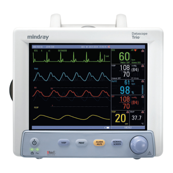
The Trio is a vital signs monitor intended for intra-hospital use on human patients. It is adaptable for use with adult and pediatric patients. The Trio is a three (3) to four (4) trace monitor. The unit has many features and functions, yet is easy to use through an integrated ™... - Page 17 General Product Description Key Features The Trio offers several new features that enhance the capabilities of the monitor. The main improvements of this release are as follows: • Support for the full line of adult and pediatric NIBP Cuffs, see Section 5.
-
Page 18: Front Panel
FIGURE 1-1 Front View of Monitor 1. Alarm Light Illuminates when an alarm is triggered. 2. Display 8.4” color TFT LCD (800 x 600 resolution). 3. Front Panel Keypad ™ Navigator Knob and dedicated quick-action keys. Trio™ Operating Instructions 0070-10-0666-01 1 - 3... - Page 19 The front panel keypad is used to access many main functions quickly and easily (see FIGURE 1-2). FIGURE 1-2 Keypad POWER Press this key to power the Trio ON or OFF. NOTE: The power supply and battery charger are active any time AC...
- Page 20 Text Edit Box. • If the menu target is a Spin Edit Box, it will display as white text on a black background. Rotate and press the knob as necessary to make a selection. Trio™ Operating Instructions 0070-10-0666-01 1 - 5...
-
Page 21: Display
Display The Trio display provides menus, waveforms, parameter information, patient information, and messages. The Trio includes various features that enable the user to customize the display. Additionally, the user default feature enables the user to save the customized settings. The display is divided into the following areas (see FIGURE 1-3): 1. - Page 22 Keypad) to exit all menus and return to the normal screen. If the user does not perform any screen operation for 30 seconds, the menu will be removed automatically and the screen will return to the normal display mode. Trend displays do not time out. Trio™ Operating Instructions 0070-10-0666-01 1 - 7 To Purchase, Visit Avobus.com...
- Page 23 • Pulse Rate (PR) (Unit: bpm) • SpO (Unit: %) • Pulse Amplitude Indicator D. IBP • Systolic, Diastolic, Mean (Units: mmHg or kPa) RESP • Respiration Rate (Units: rpm) TEMP • Temperature (Units: °C or °F) 1 - 8 0070-10-0666-01 Trio™ Operating Instructions...
- Page 24 • The MENU icon is used to access the SYSTEM MENU. It is a rectangular icon positioned below the parameter tiles and is the same width as that area. Trio™ Operating Instructions 0070-10-0666-01 1 - 9...
-
Page 25: Left Side Panel
A green LED that indicates that the recorder is receiving power 4. Battery compartment The housing for the optional, user-replaceable, rechargeable battery (sealed lead acid or Lithium Ion) 1 - 10 0070-10-0666-01 Trio™ Operating Instructions To Purchase, Visit Avobus.com or call 1-800-674-3655... -
Page 26: Right Side Panel
A standard 1/4” phone jack is used to mate with the YSI series 400 temperature probe. 5. NIBP Quick-Connect Rectus* Pneumatic Fitting This pneumatic fitting is used to attach the NIBP hose to the unit. Quick Connect Pneumatic Fittings available from Rectus-TEMA Corporation. Trio™ Operating Instructions 0070-10-0666-01 1 - 11... -
Page 27: Rear Panel
The analog signal output connector may be used with a oscillometer, pen recorder or other external devices (see section 4). The connector is a BNC jack. NOTE: After connecting any external device to the Analog Output, verify that leakage currents do not exceed accepted limits. 1 - 12 0070-10-0666-01 Trio™ Operating Instructions... - Page 28 3. Serial Port (SP1) or VGA Output (RD1) Trio monitors bearing a model number of 0998-00-0600-4XXXX are equipped with a 9-position D-shell serial port connector. Trio monitors bearing a model number of 0998-00- 0600-0XXXX or 0998-00-0600-2XXXX are equipped with a 15-position D-Shell VGA output connector.
- Page 29 Rear Panel General Product Description This page intentionally left blank. 1 - 14 0070-10-0666-01 Trio™ Operating Instructions...
-
Page 30: Getting Started
Operations Getting Started The Trio features default factory settings that enable monitoring to begin without setting waveforms, parameters, alarms, or functions. Each of these settings can be changed based on specific patient or departmental needs. Certain operating characteristics (e.g. NIBP start pressure) are based on the selected patient size. -
Page 31: Setting The Clock (Date And Time)
(from the menu or the Front Panel Keypad) to exit the menu and return to the normal screen. Menus The Trio menu system is accessed using the Navigator™ Knob. The flexibility of the menu system enables the configuration of various features including the monitored parameters, waveform sweep speed, audio volume, and parameter colors. -
Page 32: System Menu
SYSTEM MENU (FIGURE 2-1) is displayed. From the SYSTEM MENU, select a submenu. FIGURE 2-1 System Menu 2.3.1 Patient Setup Select PATIENT SETUP from the SYSTEM MENU. The PATIENT SETUP menu (FIGURE 2- 2) is displayed. FIGURE 2-2 Patient Setup Menu Trio™ Operating Instructions 0070-10-0666-01 2 - 3... - Page 33 Select NO to continue monitoring the current patient, maintain the stored record of the current patient and exit the menu. NOTE: Selecting YES will delete all information related to the currently monitored patient. FIGURE 2-3 Confirmation Dialog Box 2 - 4 0070-10-0666-01 Trio™ Operating Instructions...
-
Page 34: List Trend
Refer to "Trends" on page 2-76 for details on List Trend functions. 2.3.3 Graphic Trend To access the GRAPHIC TREND menu/display, select GRAPHIC TREND from the SYSTEM MENU. Refer to "Trends" on page 2-76 for details on Graphic Trend functions. Trio™ Operating Instructions 0070-10-0666-01 2 - 5 To Purchase, Visit Avobus.com... -
Page 35: Mark Event
Marked Events will not be saved if the menu times out. 2.3.5 Monitor Setup 1. Select MONITOR SETUP from the SYSTEM MENU. The MONITOR SETUP menu, containing various submenus (FIGURE 2-5), is displayed. FIGURE 2-5 Monitor Setup Menu 2 - 6 0070-10-0666-01 Trio™ Operating Instructions... - Page 36 SETUP menu and return to the previous menu. Select NORMAL SCREEN (from the menu or the Front Panel Keypad) to exit the menu and return to the normal screen. FIGURE 2-6 Time Setup Menu Trio™ Operating Instructions 0070-10-0666-01 2 - 7...
- Page 37 Two (2) waveforms can not be set to the same parameter. Attempting to set a duplicate parameter will cause the previous selection to default to the next available parameter waveform. 2 - 8 0070-10-0666-01 Trio™ Operating Instructions To Purchase, Visit Avobus.com or call 1-800-674-3655...
- Page 38 The recorder is optional. Select PREVIOUS MENU to return to the previous menu. Select NORMAL SCREEN (from the menu or the Front Panel Keypad) to exit the menu and return to the normal screen. Trio™ Operating Instructions 0070-10-0666-01 2 - 9...
- Page 39 Front Panel Keypad) to exit the menu and return to the normal screen. NOTE: If the optional IBP is not installed, it will not be displayed in the MODULE SETUP menu. 2 - 10 0070-10-0666-01 Trio™ Operating Instructions...
- Page 40 • MODE 1 – provides an enhanced view angle and a less smooth wave. This mode should be used when the Trio is being viewed from an angle. In most instances, this mode will provide optimal viewing of waveform data. (MODE 1 is the factory default setting.) •...
- Page 41 Factory Default Settings.) 2. Select PREVIOUS MENU to return to the previous menu. Select NORMAL SCREEN (from the menu or the Front Panel Keypad) to exit the menu and return to the normal screen. 2 - 12 0070-10-0666-01 Trio™ Operating Instructions...
-
Page 42: Maintenance
Select NO to cancel the task. FIGURE 2-13 Confirmation Dialog Box 2.3.6 Maintenance Refer to the Trio Service Manual (Part Number 0070-00-0627-03) for details on maintenance functions. 2.3.7 Normal Screen Select NORMAL SCREEN to exit the SYSTEM MENU and return to the normal screen. -
Page 43: Parameter Menus
With the Trio, ECG can be obtained by using either a 3 Lead or 5 Lead ECG cable in conjunction with a lead set and skin electrodes. For best performance and safety, inspect the ECG cables and electrodes daily. - Page 44 Electrode patches are disposable and should be applied only once. Try to avoid reusing the exact same electrode site during reapplication. If an electrode becomes wet with fluid, change the electrode patch. Trio™ Operating Instructions 0070-10-0666-01 2 - 15...
- Page 45 • Place the LL (red) electrode on the • Place the F (green) electrode on the patient’s lower left abdomen within the patient’s lower left abdomen within the rib cage frame. rib cage frame. 2 - 16 0070-10-0666-01 Trio™ Operating Instructions...
- Page 46 • Place the C (white) electrode in one of the V-lead positions (V1 – V6) depicted the C-lead (C1 – C6) positions depicted in the following section. in the following section. Trio™ Operating Instructions 0070-10-0666-01 2 - 17 To Purchase, Visit Avobus.com...
- Page 47 • V6 - Place the electrode at the fifth • C6 - Place the electrode at the fifth intercostal space on the mid-axillary line intercostal space on the mid-axillary line 2 - 18 0070-10-0666-01 Trio™ Operating Instructions...
- Page 48 Select ECG Lead II on the monitor. Lead II is the direct electrical line between the RA the direct electrical line between the R (red) (white) electrode and the LL (red) electrode. electrode and the F (green) electrode. Trio™ Operating Instructions 0070-10-0666-01 2 - 19...
- Page 49 Lead II is the direct electrical line between the L (red) electrode and the F (green) the RA (white) electrode and the LL (red) electrode. electrode. 2 - 20 0070-10-0666-01 Trio™ Operating Instructions To Purchase, Visit Avobus.com or call 1-800-674-3655...
- Page 50 Since a TENS unit transmits electrical impulses, avoid placing ECG electrode patches near the TENS electrodes. ECG electrode patches may need to be repositioned and the ECG lead viewed may need to be adjusted until the optimum ECG tracing is obtained. Trio™ Operating Instructions 0070-10-0666-01 2 - 21...
- Page 51 ESIS cable. Respiration from ECG is not available if the ESIS cable is used. • Plug the patient cable firmly into the ECG connector on the Trio. An ECG waveform will begin to display in the ECG waveform tile and the heart rate will be displayed in the ECG parameter tile to the right (see FIGURE 2-26).
- Page 52 MONITOR mode should be used for typical monitoring conditions. Its frequency range of 0.50 Hz to 40 Hz filters out most low frequency noise that can be generated by patient motion, muscle artifact, etc. Trio™ Operating Instructions 0070-10-0666-01 2 - 23 To Purchase, Visit Avobus.com...
- Page 53 To access the ECG SETUP menu, select ECG from the ECG parameter tile using the Navigator™ Knob. Once in the ECG SETUP menu, use the Navigator Knob to adjust settings. To close the menu, select NORMAL SCREEN (from the menu or the Front Panel Keypad). 2 - 24 0070-10-0666-01 Trio™ Operating Instructions...
- Page 54 (pulse rate) is displayed in the ECG and SpO2 parameter tiles. This label and its associated numeric value are displayed in the same color as the SpO numeric value. The audible tone sounds at the peak of each pulse wave. Trio™ Operating Instructions 0070-10-0666-01 2 - 25...
- Page 55 Beep volume is the volume of the audible tone for the Heart Rate. The selections are OFF, LOW, MED and HIGH. RESTORE Allows the user to restore the ECG user default configuration. DEFAULTS FIGURE 2-28 Confirmation Dialog Box 2 - 26 0070-10-0666-01 Trio™ Operating Instructions To Purchase, Visit Avobus.com or call 1-800-674-3655...
- Page 56 Ensure proper connection. (cable to secured monitor, cable to lead, lead to electrode). Electrodes dry or loose Repeat skin preparation and apply fresh, moist electrodes. Cable or leadwires damaged Check with a continuity tester. Trio™ Operating Instructions 0070-10-0666-01 2 - 27...
- Page 57 Check with a continuity tester. Base Line Wander Patient moving excessively. Secure lead wires and cable to patient. Patient respiration variance. Reposition electrodes Electrodes dry or loose Repeat skin preparation and apply fresh, moist electrodes. 2 - 28 0070-10-0666-01 Trio™ Operating Instructions...
-
Page 58: Respiration Monitoring
2.4.2 Respiration Monitoring The Trio utilizes thoracic impedance to measure respiration. This is accomplished by passing a small electrical signal across the RA and LL (R and F) ECG limb leads. This signal changes as the patient's chest wall rises and falls during the breath cycle. The change of impedance between the two (2) electrodes, (due to the thoracic movement), produces a respiratory waveform on the screen. - Page 59 Physiological alarms occur when the patient’s respiration rate is equal to or exceeds set alarm limits. Technical alarms are any Respiratory- related alarms, which are not physiological, such as functional failures. 2 - 30 0070-10-0666-01 Trio™ Operating Instructions...
- Page 60 Respiration detection No Respiration rate Cable not connected Check cable displayed ESIS cable in use Use non-ESIS cable only for respiration detection Cardiovascular Artifact Detected Check patient, notify physician Change Respiration scale Adjust leads Trio™ Operating Instructions 0070-10-0666-01 2 - 31...
-
Page 61: Spo Monitoring
SpO parameter tile (FIGURE 2-31) along with the Pulse Rate and the Pulse Amplitude Indicator. The indicator provides a graphic depiction of the relative pulse volume. When the Trio is equipped with Nellcor® OxiMax® SpO , the SpO parameter tile displays a SatSeconds™... - Page 62 2 - 3 hours; more frequent examinations may be required for different patients. Change the sensor site if signs of circulatory compromise occur. Trio™ Operating Instructions 0070-10-0666-01 2 - 33...
- Page 63 To prevent damage, do not soak or immerse the sensor in any liquid solution. Do not attempt to sterilize. CAUTION: Excessive ambient light may cause inaccurate measurements. In such cases, cover the sensor site with opaque material. 2 - 34 0070-10-0666-01 Trio™ Operating Instructions...
- Page 64 (if SpO is selected in the TRACE SETUP menu). NOTE: To disconnect the cable from the Trio, squeeze the tabs on the sides of the connector and then pull it straight out. CAUTION: Prolonged and continuous monitoring may increase the risk of skin erosion and pressure necrosis at the site of the sensor.
- Page 65 Allows the user to set the lower limit of the Pulse Rate alarm. (See “Masimo SET SpO2 Alarm Limits” on page 2-38.) SWEEP Adjusts the speed of the SpO waveform on the display. The selections are 12.5 and 25.0 mm/sec. 2 - 36 0070-10-0666-01 Trio™ Operating Instructions...
- Page 66 “SpO2 Sensor OFF” condition occurs. If OFF is selected, then the audio beep alarm will not sound when an “SpO2 Sensor OFF” condition occurs. RESTORE Allows the user to restore the SpO user default configuration. DEFAULTS FIGURE 2-33 Confirmation Dialog Box Trio™ Operating Instructions 0070-10-0666-01 2 - 37...
- Page 67 Customer Support. : Board Fault Masimo SET board failed to Notify hospital technician or Customer operate properly Support : Sensor Fault Defective Sensor Replace sensor 2 - 38 0070-10-0666-01 Trio™ Operating Instructions To Purchase, Visit Avobus.com or call 1-800-674-3655...
- Page 68 SpO parameter tile (if SpO is selected in the TRACE SETUP menu). NOTE: To disconnect the cable from the Trio, squeeze the tabs on the sides of the connector and then pull it straight out. Trio™ Operating Instructions 0070-10-0666-01...
- Page 69 Allows the user to set the upper limit of the SpO alarm. (See “Nellcor SpO2 Alarm Limits” on page 2-42.) SPO2 ALM LO Allows the user to set the lower limit of the SpO alarm. (See “Nellcor SpO2 Alarm Limits” on page 2-42.) 2 - 40 0070-10-0666-01 Trio™ Operating Instructions...
- Page 70 SatSeconds limit has not been reached. RESTORE Allows the user to restore the SpO user default configuration. DEFAULTS FIGURE 2-35 Confirmation Dialog Box Trio™ Operating Instructions 0070-10-0666-01 2 - 41 To Purchase, Visit Avobus.com or call...
- Page 71 SpO2 module failure or Notify hospital technician or Customer communication error. Support SPO2 ALM LMT ERR Functional failure. Notify hospital technician or Customer Support PR ALM LMT ERR Functional failure. Notify hospital technician or Customer Support 2 - 42 0070-10-0666-01 Trio™ Operating Instructions...
- Page 72 Operations Parameter Menus MESSAGE REASON ACTION SPO2 EXCEED SpO2 value exceeds the Check patient, notify physician measurement range. PR EXCEED PR value exceeds the Check patient, notify physician measurement range. Trio™ Operating Instructions 0070-10-0666-01 2 - 43...
-
Page 73: Nibp Monitoring
INTERVAL. Each mode will display the Systolic (SYS), Diastolic (DIA) and Mean Arterial Pressure (MAP) values in the NIBP tile. MANUAL MODE Each time a measurement is desired, press the NIBP key on the Trio keypad to initiate a measurement. Press the NIBP key a second time to stop a measurement already in progress. - Page 74 After the first successful measurement, the subsequent inflation pressure for the same patient will be 50 ±10 mmHg above the previous systolic pressure measurement. Upon power ON of the Trio, the NIBP unit of measure defaults to the most recent setting made in the NIBP SETUP menu.
- Page 75 NIBP parameter tile as “CUFF:XXX”. If a measurement cannot be obtained, the Trio automatically reinflates the cuff to 30 – 60 mmHg higher than the initial inflation pressure, but will not exceed the maximum cuff pressure listed in the “NIBP Sub-System Functional Requirements”, section 6.2.6.5.
- Page 76 Please start Displayed after selecting an INTERVAL in the NIBP SETUP Measurement over Displayed after an NIBP measurement has been manually stopped by pressing the NIBP key during the measurement. Trio™ Operating Instructions 0070-10-0666-01 2 - 47 To Purchase, Visit Avobus.com...
- Page 77 Allows the user to set the upper limit of the Systolic NIBP alarm. (See “NIBP Alarm Limits” on page 2-50.) SYS ALM LO Allows the user to set the lower limit of the Systolic NIBP alarm. (See “NIBP Alarm Limits” on page 2-50.) 2 - 48 0070-10-0666-01 Trio™ Operating Instructions...
- Page 78 When the time-out interval has been exceeded, the NIBP measurement is replaced by dashes. RESTORE Allows the user to restore the NIBP user default configuration. DEFAULTS FIGURE 2-39 Confirmation Dialog Box Trio™ Operating Instructions 0070-10-0666-01 2 - 49...
- Page 79 This may result in high pressure readings. Over-wrapping a slender arm may also give erroneous pressure readings due to excessive force exerted on the arm. 2 - 50 0070-10-0666-01 Trio™ Operating Instructions To Purchase, Visit Avobus.com or call 1-800-674-3655...
- Page 80 5. Gently place the cuff on the patient. If the cuff is too snug, it won't work properly. On infants, the cuff should easily move over the limb. Trio™ Operating Instructions 0070-10-0666-01 2 - 51...
- Page 81 Check patient, notify physician Blood pressure is out of range Check patient, verify BP with manual method, notify physician Incorrect cuff size / brand Measure patient’s limb, verify cuff size. Use only approved accessories. 2 - 52 0070-10-0666-01 Trio™ Operating Instructions...
-
Page 82: Temperature Monitoring
Parameter Menus 2.4.5 Temperature Monitoring The temperature (TEMP) measurement function of the Trio is designed to take continuous temperature readings from the YSI 400 series probes. One (1) temperature channel is standard on the Trio. 1. If using a disposable temperature probe: Connect the preferred disposable temperature probe into the reusable temperature cable. - Page 83 Physiological alarms occur when the patient’s temperature values are equal to or exceed set alarm limits. Technical alarms are any temperature-related alarms, which are not physiological, such as functional failures. 2 - 54 0070-10-0666-01 Trio™ Operating Instructions...
- Page 84 Poor contact from probes to body Check the body surface contact at not working the probe tip Reposition or apply thermoconductive gel Temperature not Cable not plugged in Check cable and probe displayed Trio™ Operating Instructions 0070-10-0666-01 2 - 55...
-
Page 85: Ibp Monitoring (Optional)
Pressure transducers are protected against the effects of defibrillation and electrocautery. NOTE: Please refer to the local hospital policy for requirements for routine zeroing and calibration of invasive pressure lines. 2 - 56 0070-10-0666-01 Trio™ Operating Instructions To Purchase, Visit Avobus.com or call 1-800-674-3655... - Page 86 • A successful message will be displayed in the IBP ZERO menu when the invasive line has been zeroed successfully • A failure message will be displayed if the transducer fails to zero Trio™ Operating Instructions 0070-10-0666-01 2 - 57...
- Page 87 Navigator™ Knob. Once in the IBP SELECT menu, use the Navigator Knob to open the IBP SETUP menu. To close the menu, select NORMAL SCREEN (from the menu or the Front Panel Keypad). 2 - 58 0070-10-0666-01 Trio™ Operating Instructions...
- Page 88 Adjusts the speed of the IBP waveform on the display. The selections are 12.5 and 25.0 mm/sec. UNITS Allows the user to select the units of measurement for IBP. The selections are mmHg or kPa. Trio™ Operating Instructions 0070-10-0666-01 2 - 59 To Purchase, Visit Avobus.com...
- Page 89 HI and LO set limits of the scale. FIGURE 2-45 IBP Scale Adjust Menu RESTORE Allows the user to restore the IBP user default configuration. DEFAULTS FIGURE 2-46 Confirmation Dialog Box 2 - 60 0070-10-0666-01 Trio™ Operating Instructions...
- Page 90 Physiological alarms occur when the patient’s pressure values are equal to or exceed set alarm limits. Technical alarms are any IBP-related alarms, which are not physiological, such as functional failures. Trio™ Operating Instructions 0070-10-0666-01 2 - 61...
- Page 91 Check and zero the transducer Abnormally high or Transducer too HIGH or too LOW in Check patient, adjust transducer, low readings relation to patient's heart re-zero 2 - 62 0070-10-0666-01 Trio™ Operating Instructions To Purchase, Visit Avobus.com or call 1-800-674-3655...
-
Page 92: Alarms
Priority 1, 2 or 3. When the Trio is turned ON, an audible tone and the alarm light will indicate that the audio and visual alarm functions of the monitor are working properly. If the tone is not heard and/ or the alarm light does not flash when the unit is turned ON, contact the hospital biomedical technician or a Customer Service representative. -
Page 93: Alarm Priorities
SETUP. The selected ALARM SETUP menu will determine the other available menu selections. NOTE: For more information on parameter alarms and instructions for setting these alarms, refer to the parameter-specific section of this Operator's Manual. 2 - 64 0070-10-0666-01 Trio™ Operating Instructions... - Page 94 Example: Elapsed time = 2min, New ALM MUTE TIME = 10min, Alarm Mute continues to be active for 8 minutes and then deactivates. Trio™ Operating Instructions 0070-10-0666-01 2 - 65 To Purchase, Visit Avobus.com...
- Page 95 Allows the user to set the upper limit of the HR alarm. (See “Heart Rate Alarm Limits” on page 2-27.) HR ALM LO Allows the user to set the lower limit of the HR alarm. (See “Heart Rate Alarm Limits” on page 2-27.) 2 - 66 0070-10-0666-01 Trio™ Operating Instructions...
- Page 96 ALM SEL Choose SPO2 ALARM SETUP. (Alarm Selection) ALM PRIORITY Allows the user to select the priority of the alarm. Choices are 1, 2 and 3. Priority 1 alarms are considered the most serious. Trio™ Operating Instructions 0070-10-0666-01 2 - 67...
- Page 97 As a safety precaution, if three (3) SPO2 alarm violations occur within 60 seconds, a priority 2 alarm will trigger even if the SatSeconds limit has not been reached. 2 - 68 0070-10-0666-01 Trio™ Operating Instructions To Purchase, Visit Avobus.com or call 1-800-674-3655...
- Page 98 Allows the user to set the lower limit of the Systolic NIBP alarm. (See “NIBP Alarm Limits” on page 2-50.) MEAN ALM HI Allows the user to set the upper limit of the Mean NIBP alarm. (See “NIBP Alarm Limits” on page 2-50.) Trio™ Operating Instructions 0070-10-0666-01 2 - 69...
- Page 99 Allows the user to set the upper limit of the Diastolic NIBP alarm. (See “NIBP Alarm Limits” on page 2-50.) DIA ALM LO Allows the user to set the lower limit of the Diastolic NIBP alarm. (See “NIBP Alarm Limits” on page 2-50.) 2 - 70 0070-10-0666-01 Trio™ Operating Instructions...
- Page 100 (See “IBP Alarm Limits” on page 2-61.) MEAN ALM HI Allows the user to set the upper limit of the Mean IBP alarm. (See “IBP Alarm Limits” on page 2-61.) Trio™ Operating Instructions 0070-10-0666-01 2 - 71 To Purchase, Visit Avobus.com...
- Page 101 Allows the user to set the upper limit of the Diastolic IBP alarm. (See “IBP Alarm Limits” on page 2-61.) DIA ALM LO Allows the user to set the lower limit of the Diastolic IBP alarm. (See “IBP Alarm Limits” on page 2-61.) 2 - 72 0070-10-0666-01 Trio™ Operating Instructions...
- Page 102 Allows the user to set the upper limit of the RESP alarm. (See “Respiration Rate Alarm Limits” on page 2-30.) ALM LO Allows the user to set the lower limit of the RESP alarm. (See “Respiration Rate Alarm Limits” on page 2-30.) Trio™ Operating Instructions 0070-10-0666-01 2 - 73...
- Page 103 “Temperature Alarm Limits” on page 2-54.) TEMP ALM LO Allows the user to set the lower limit of the TEMP alarm. (See “Temperature Alarm Limits” on page 2-54.) 2 - 74 0070-10-0666-01 Trio™ Operating Instructions To Purchase, Visit Avobus.com or call 1-800-674-3655...
-
Page 104: Alarm Troubleshooting
The cell battery has low capacity, the cell Check the battery, replace if battery is not installed or the connection necessary. If the failure still is loose exists, notify hospital technician or Customer Support Trio™ Operating Instructions 0070-10-0666-01 2 - 75... -
Page 105: Trends
* indicates mean value. NOTE: When the monitor is powered OFF, graphic trend data is maintained for 2 hours. If the monitor remains OFF for more than 2 hours, the graphic trend data is deleted. 2 - 76 0070-10-0666-01 Trio™ Operating Instructions... - Page 106 • To print the graphic trend data for the currently selected parameter, select PRINT from the GRAPHIC TREND menu. • To stop the print job currently in progress, select PRINT on the front panel keypad. Trio™ Operating Instructions 0070-10-0666-01 2 - 77 To Purchase, Visit Avobus.com...
- Page 107 TREND menu. 9. Select PREVIOUS MENU to return to the SYSTEM MENU. Select NORMAL SCREEN (from the menu or the Front Panel Keypad) to exit the menu and return to the normal screen. 2 - 78 0070-10-0666-01 Trio™ Operating Instructions...
-
Page 108: List Trend
IBP, RESP and TEMP. Use the SCROLL key to view additional parameter data. NOTE: When the monitor is powered OFF, list trend data is maintained for 2 hours. If the monitor remains OFF for more than 2 hours, the list trend data is deleted. Trio™ Operating Instructions 0070-10-0666-01 2 - 79... - Page 109 To exit the LIST TREND menu/display and return to the SYSTEM MENU, select PREVIOUS MENU. To exit the LIST TREND menu/display and return to the normal screen, select NORMAL SCREEN (from the menu or the Front Panel Keypad). 2 - 80 0070-10-0666-01 Trio™ Operating Instructions To Purchase, Visit Avobus.com or call 1-800-674-3655...
- Page 110 6. Select PRINT to initiate a printout of all trend data of this time segment, including NIBP. 7. Select PREVIOUS MENU to return to the SYSTEM menu. Select NORMAL SCREEN (from the menu or the Front Panel Keypad) to exit the menu and return to normal screen. Trio™ Operating Instructions 0070-10-0666-01 2 - 81...
-
Page 111: Recorder (Optional)
The optional Trio Recorder provides a printed record of all patient monitored parameters, including numeric and waveform data. It is a two-trace thermal strip chart recorder. The Trio recorder uses plain white thermal paper, 50mm wide (part number 0683-00-0505-02.) See section 4.7 for Paper Replacement Instructions. - Page 112 5. Press the PRINT key again to stop a printout that is already in progress. NOTE: If a printout has started, and a parameter alarm prompts an additional printout, the alarm printout will not begin until the current printout is complete. Trio™ Operating Instructions 0070-10-0666-01 2 - 83 To Purchase, Visit Avobus.com...
- Page 113 Recorder (Optional) Operations Interval Real-Time Printout The Trio can be set to print automatically at regular intervals, as designated by the user. To activate the interval print feature: 1. Select INTERVAL from the PRINTER SETUP menu. 2. Use the Navigator™ Knob to choose the interval at which an automatic printout will occur.
- Page 114 SYSTEM MENU. From the MAINTENANCE menu, select ERROR LOG. Select PRINT from the ERROR LOG menu. To stop the print job currently in progress, select the PRINT key on the front panel keypad. FIGURE 2-62 Example, Error Log Printout Trio™ Operating Instructions 0070-10-0666-01 2 - 85...
-
Page 115: Recorder Troubleshooting
SELFTEST ERR notify hospital technician or call Customer Support. PRINTER INIT Functional failure Power cycle unit. If message reappears, ERR1 contact hospital technician or Customer Support. 2 - 86 0070-10-0666-01 Trio™ Operating Instructions To Purchase, Visit Avobus.com or call 1-800-674-3655... -
Page 116: Defaults
Defaults Default Configurations Trio has four default configurations. • Factory Default Configuration • User Default Configuration • Current Configuration • Non-Volatile Configuration 3.1.1 Factory Default Configuration The Factory Default Configuration is initially set by the manufacturer. These settings cannot be changed by the user. If the user changes settings to be different from the Factory Default settings, the Factory Default Configuration can be restored as follows: 1. - Page 117 PRINTER SETUP Print Waveform 1 Print Waveform 2 IBP (if the IBP module is installed) SpO2 (if no IBP module is installed) Print Time (waveform length) 8 Seconds Print Interval Print Speed 25 mm/s 3 - 2 0070-10-0666-01 Trio™ Operating Instructions...
- Page 118 Resp Sweep Speed 12.5 mm/s Resp Wave Scale Resp Rate Alarm Limit Hi Resp Rate Alarm Limit Lo SPO2 SETUP SpO2 Alarm Print SpO2 Alarm Priority Trio™ Operating Instructions 0070-10-0666-01 3 - 3 To Purchase, Visit Avobus.com or call 1-800-674-3655...
- Page 119 IBP Alarm IBP Alarm Print IBP Alarm Priority IBP Units mmHg (for all languages) IBP Sweep Speed 25 mm/s IBP SCALE ADJUST IBP Scale ART High IBP Scale PA High IBP Scale CVP High 3 - 4 0070-10-0666-01 Trio™ Operating Instructions...
- Page 120 IBP CVP_Mean Alarm Limit Lo IBP RAP_Mean Alarm Limit Hi IBP RAP_Mean Alarm Limit Lo IBP LAP_Mean Alarm Limit Hi IBP LAP_Mean Alarm Limit Lo IBP ICP_Mean Alarm Limit Hi IBP ICP_Mean Alarm Limit Lo Trio™ Operating Instructions 0070-10-0666-01 3 - 5...
-
Page 121: Current Configuration
Select NO to cancel the task. FIGURE 3-3 Confirmation Dialog Box NOTE: At initial startup of the Trio, the User Default Configuration is identical to the Factory Default Configuration. NOTE: Selecting a new patient size automatically activates the User Default Configuration for that patient size. -
Page 122: Non-Volatile Configuration
* GENDER blank/empty field SIZE Adult * HT. (Height) blank/empty field * WT. (Weight) blank/empty field * BIRTH (day, month, year) blank/empty field MODULE SETUP submenu in ECG/RESP/TEMP/SpO2/IBP/NIBP FACTORY menu System Time 2001-12-31 23:59:59 Trio™ Operating Instructions 0070-10-0666-01 3 - 7... - Page 123 Default Configurations Defaults This page intentionally left blank. 3 - 8 0070-10-0666-01 Trio™ Operating Instructions...
-
Page 124: User Maintenance
This section of the manual outlines routine maintenance to be performed by the user and/or biomedical technician. The Trio Monitor is designed for stable operation over long periods of time and under normal circumstances should not require technical maintenance beyond circumstances described in this section. -
Page 125: Decontamination Of The Monitor
Fingerprints and stains may be removed by using a liquid lens cleaner and a soft cloth. DO NOT wipe a dry screen or use alcohol or a solvent containing chlorinated hydrocarbon. 4 - 2 0070-10-0666-01 Trio™ Operating Instructions... -
Page 126: Care And Cleaning Of Accessories
To prevent damage, do not soak or immerse the sensor in any liquid solution. Do not attempt to sterilize. CAUTION: Do not use sensors or cables that are damaged or have deteriorated. Trio™ Operating Instructions 0070-10-0666-01 4 - 3... -
Page 127: Blood Pressure Cuffs
Clean and disinfect the cuff according to the instructions. 4.4.2.2 Reusable Bladderless Cuffs Clean cuffs with warm water and a mild detergent. Do not use a detergent containing hard conditioners, softeners, or fragrances. 4 - 4 0070-10-0666-01 Trio™ Operating Instructions To Purchase, Visit Avobus.com or call 1-800-674-3655... - Page 128 Do not use the same cuff on any other patient. Do not sterilize or use an autoclave on disposable cuffs. NOTE: Disposable cuffs can be cleaned using a mild soap solution and dried with a clean cloth. For cuffs with bladders, remove bladder before cleaning. Trio™ Operating Instructions 0070-10-0666-01 4 - 5...
-
Page 129: Temperature Sensor Cleaning And Disinfection (Reusable)
0069 (for a Lithium Ion battery). Battery Maintenance The batteries used in the Trio monitor are of sealed lead acid construction and Lithium Ion construction. These types of batteries may be subject to local regulations regarding disposal. At the end of battery life, dispose of the batteries in accordance with any local regulations. -
Page 130: Recorder Maintenance
FIGURE 4-2 Two-trace, integral recorder 1. Recorder door Open this door to access the recorder. 2. Recorder door latch Gently pull down on this latch to open the recorder door. Trio™ Operating Instructions 0070-10-0666-01 4 - 7 To Purchase, Visit Avobus.com... -
Page 131: Recorder Paper Replacement
7. Pull the paper out approximately four (4) inches. 8. Roller lever must be returned to the down position before closing the recorder door. Holding the paper, close the recorder door. 4 - 8 0070-10-0666-01 Trio™ Operating Instructions... -
Page 132: Care And Storage Of Thermal Paper
NOTE: Do not autoclave, radiation or steam sterilize ECG cables or leadwires. NOTE: Extended exposure to Ethylene Oxide gas may shorten life of the ECG cables and leadwires, leading to poor signal quality. Trio™ Operating Instructions 0070-10-0666-01 4 - 9... - Page 133 Care and Cleaning of ECG Cables and Leadwires User Maintenance This page intentionally left blank. 4 - 10 0070-10-0666-01 Trio™ Operating Instructions To Purchase, Visit Avobus.com or call 1-800-674-3655...
-
Page 134: Accessories
Adult Long, Navy Blue 0998-00-0003-57 (27.5 – 36.5 cm arm circumference), latex-free Child, Green 0998-00-0003-52 (13.8 – 21.5 cm arm circumference), latex-free Small Child, Orange 0998-00-0003-51 or (9 – 14.8 cm arm circumference), latex-free 0683-15-0001-01 Trio™ Operating Instructions 0070-10-0666-01 5 - 1... - Page 135 Adult, 25 – 35 cm (arm circumference), latex free, box of 10 0683-14-0003-01 Large Adult, 33 – 47 cm (arm circumference), latex free, 0683-14-0004-01 box of 10 Thigh, 46 – 66 cm (arm circumference), latex free, box of 5 0683-14-0005-01 5 - 2 0070-10-0666-01 Trio™ Operating Instructions...
-
Page 136: Oximetry Sensors And Accessories
® LNCS PDTX Pediatric single patient adhesive sensors (20/Box) 0600-00-0122 ® LNCS INF-L Infant single patient adhesive sensors (20/Box) 0600-00-0123 LNC-4 SpO2 Patient cable, 4' 0012-00-1652 Trio™ Operating Instructions 0070-10-0666-01 5 - 3 To Purchase, Visit Avobus.com or call 1-800-674-3655... -
Page 137: Reusable Temperature Probes
Esophageal/Rectal, 12 Fr, ER 400-12 0206-03-0212-02 Skin, SK 400 0206-03-0300-02 Instrument Cable, 400 Series 0012-00-0975 5.1.5 ECG Accessories 5.1.5.1 ECG Cables DESCRIPTION PART NUMBERS Straight, 10’ (3.1 m) 0012-00-1255-01 Straight, 20’ (6.1 m) 0012-00-1255-02 5 - 4 0070-10-0666-01 Trio™ Operating Instructions... -
Page 138: Ibp Accessories
P10EZ-1 Miniature (Reusable) 0682-00-0085 P23XL-1 Transducer (Reusable) 0682-00-0084 Cable, Interface, Transducer 0012-00-1245 5.1.7 Miscellaneous Accessories DESCRIPTIONS PART NUMBER DIAP Cable Assembly 10’ 0012-00-1275-01 Recorder Chart Paper (12 Rolls) 0683-00-0505-02 Battery, Sealed Lead Acid 0146-00-0043 Trio™ Operating Instructions 0070-10-0666-01 5 - 5... -
Page 139: Mounting Kits And Accessories
(includes Rolling Stand and Mounting Bracket) Trio Value Rolling Stand 0436-00-0224-01 Trio Value Rolling Stand Mounting Bracket 0406-00-0856-01 Trio Standard Wall Mount Kit 0040-00-0337-01 Trio VHM (Variable Height Mount) Wall Mount Kit 0040-00-0337-02 Trio Mounting Bracket Kit 0040-00-0338 5.1.9 Replacement Parts, Trio Rolling Stand DESCRIPTIONS... -
Page 140: Appendix
Automatic Cycling Indirect Blood Pressure Measuring Equipment IEC 60601-2-34:2000/ Particular Requirements for the Safety of EN 60601-2-34:2000 Direct Blood Pressure Monitoring Equipment IEC 60601-2-27:1994/ Particular Requirements for the Safety of EN 60601-2-27:1994 Electrocardiograph Monitoring Equipment Trio™ Operating Instructions 0070-10-0666-01 6 - 1... -
Page 141: Safety Designations
Protection Against Ingress of Liquid's Not protected (Ordinary) - IPX0 per IEC 529 Degree of electrical connection between Equipment designed for direct electrical and equipment and patient - non-electrical connection to the patient Degree of Mobility: Transportable 6 - 2 0070-10-0666-01 Trio™ Operating Instructions... -
Page 142: Performance / Accuracy
Graphical Symbols for Electrical Equipment in Medical Practice ISO 1000:1992 + A1:1998 SI units and recommendations for the use of their multiples and of certain other units Trio™ Operating Instructions 0070-10-0666-01 6 - 3 To Purchase, Visit Avobus.com or call... -
Page 143: Environmental / Emc
Reviewer Guidance for Pre-market Notification Submission, November 1993 - draft Guidance Non-Invasive Blood Pressure (NIBP) Monitor Guidance, March 10, 1997 Non-Invasive Pulse Oximeter General Guidance, draft, September 7, 1992 Cardiac Monitor Guidance (Including Cardiotachometer and Rate Alarm), November 5, 1998 6 - 4 0070-10-0666-01 Trio™ Operating Instructions... -
Page 144: Patient Parameter Specifications
MONITOR MODE EXTENDED MODE SURGICAL MODE 0.5 to 40 Hz 0.05 to 100 Hz 1 to 20 Hz Common Mode Rejection: MONITOR MODE EXTENDED MODE SURGICAL MODE >105 dB >90 dB >105 dB Trio™ Operating Instructions 0070-10-0666-01 6 - 5... - Page 145 100 μs and with duration in the 0.1 ms to 2.0 ms range are enhanced on the display when the Pacer Enhancement Mode is turned ON. 6 - 6 0070-10-0666-01 Trio™ Operating Instructions To Purchase, Visit Avobus.com or call 1-800-674-3655...
-
Page 146: Ansi/Aami Ec13-2002 Compliance
Figure 3a (Ventricular Bigeminy) - 80 bpm Figure 3b (Slow Alternating Ventricular Bigeminy) - 60 bpm Figure 3c (Rapid Alternating Ventricular Bigeminy) - 120 bpm Figure 3d (Bi-directional Systoles) - 90 bpm Trio™ Operating Instructions 0070-10-0666-01 6 - 7... -
Page 147: Ecg Systole Detector And Heart Rate Meter
When tested in accordance with ANSI/ AAMI EC13-2002 section 4.1.4.3, the minimum input slew rate that will cause approximately 50% of Figure 5d's pulses to trigger the Trio's pacer pulse detector is 10 V/s RTI. 6.2.4 ECG Systole Detector and Heart Rate Meter The ECG heart rate meter function is derived from the ECG waveform. -
Page 148: Ecg Respiration Performance Requirements
40 to 240 bpm. The NIBP function is in accordance with the requirements of EN 60601-2-30, EN 1060-1, EN 1060-3 and ANSI/AAMI SP-10:1992. Trio™ Operating Instructions 0070-10-0666-01 6 - 9 To Purchase, Visit Avobus.com... - Page 149 ±3 mmHg over the entire range. 6.2.6.4 Heart Rate from NIBP Accuracy: ± 2 bpm or 2%, whichever is greater Resolution: 1 bpm Range: ADULT MODE PEDIATRIC MODE 40 to 240 bpm 40 to 240 bpm 6 - 10 0070-10-0666-01 Trio™ Operating Instructions...
- Page 150 The Start Pressure is automatically adjusted based on the selected patient size and is set to the following defaults: PRESSURE INCREMENT PATIENT SIZE (DEPENDING ON ALGORITHM) DEFAULT START PRESSURE Adult Mode 30 – 60 mmHg 178 ±5 mmHg Pediatric Mode 30 – 60 mmHg 133 ±5 mmHg Trio™ Operating Instructions 0070-10-0666-01 6 - 11...
-
Page 151: Ibp Parameter Sub-System Performance Characteristics
6.2.7 IBP Parameter Sub-System Performance Characteristics The Trio monitor is capable of providing invasive blood pressure (IBP) measurements from a maximum of 1 IBP channel. The IBP channel will provide three pressure readings: systolic, diastolic, and mean pressures. 6.2.8 IBP Safety Requirements The IBP function meets the safety requirements of EN 60601-2-34. -
Page 152: Temperature Parameter Performance Characteristics
Appendix Patient Parameter Specifications 6.2.9 Temperature Parameter Performance Characteristics The Trio monitor is capable of providing temperature measurements from a single temperature channel as measured from a YSI 400 probe and meets the requirements of EN12470-4:2000. 6.2.9.1 Temperature Performance Requirements... - Page 153 Pulse Rate Range and Accuracy PATIENT SIZE PULSE RATE RANGE ACCURACY DURING MOTION NO MOTION CONDITIONS CONDITIONS Adult/Pediatric 25 to 240 bpm ± 3 digits ± 5 digits Update Rate Update rate is 1 Hz. 6 - 14 0070-10-0666-01 Trio™ Operating Instructions...
- Page 154 NOTE: The sensor measurement wavelengths are nominally 660 nm for the red LED and 940 nm for the infrared LED. Maximum optical power output for LED is 4 mW. Trio™ Operating Instructions 0070-10-0666-01 6 - 15 To Purchase, Visit Avobus.com...
- Page 155 Update rate is 1 Hz. NOTE: The sensor measurement wavelengths are nominally 660 nm for the red LED and 890 nm for the infrared LED. Maximum optical power output for LED is 4 mW. 6 - 16 0070-10-0666-01 Trio™ Operating Instructions...
-
Page 156: Physical Specifications
ON/standby key, NIBP start/stop key, PRINT start/stop key, ALARM MUTE key and NORMAL SCREEN key. 6.3.2.3 Audio Indicators An audio speaker is provided to annunciate alarms, message tones and systole beep tones. Audio alarms are in accordance with EN475: 1995 Trio™ Operating Instructions 0070-10-0666-01 6 - 17... -
Page 157: Real Time Clock
DIAP Communication Protocol (model number 0998-00-0600-4XXXX) Trio Monitors bearing a model number of 0998-00-0600-4XXXX support the proprietary communication protocol DIAP (0070-00-0307) with the following exceptions: 1. The NIBP elapsed time is set to “---” when the elapsed time is greater than 999 minutes. -
Page 158: Power Supply
6.3.5 Power Supply 6.3.5.1 Power Source The Trio monitor will auto-select its power source from those available. The monitor uses the following priority in choosing the power source: 1. AC Mains Power 2. Internal battery power The monitor will operate from AC Mains power with or without the internal battery installed. -
Page 159: Data Storage
1 second. When the monitor is powered OFF, the list and graphic trend data is maintained for 2 hours. If the monitor remains OFF for more than 2 hours, the list and graphic trend data is deleted. 6 - 20 0070-10-0666-01 Trio™ Operating Instructions... -
Page 160: Printers
The SPL produced by the unit during normal operating conditions is less than 60 dBA maximum at 1 meter when measured in accordance with ISO 3744. Maximum SPL is measured with no alarms sounding, but all internal mechanical devices (i.e. pumps, fans) running. Trio™ Operating Instructions 0070-10-0666-01 6 - 21 To Purchase, Visit Avobus.com... -
Page 161: Environmental And Safety Characteristics
1 g or 0.07 mm, 57 – 62 Hz crossover frequency 10 to 500 Hz, 10 sweep cycles in each axis Random Vibration Per IEC 68-2-34 0.02 g2/Hz 20 – 500 Hz Low degree of reproducibility 9 minutes per axis 6 - 22 0070-10-0666-01 Trio™ Operating Instructions... - Page 162 Trio. See tables 6-1 through 6-4 that follow. TABLE 6-1 GUIDANCE AND DECLARATION - ELECTROMAGNETIC EMISSIONS The Trio is intended for use in the electromagnetic environment specified below. The customer or the user of the Trio should assure that it is used in such an environment. EMISSIONS...
- Page 163 Appendix TABLE 6-2 GUIDANCE AND DECLARATION - ELECTROMAGNETIC IMMUNITY The Trio is intended for use in the electromagnetic environment specified below. The customer or the user of the Trio should assure that it is used in such an environment. IMMUNITY...
- Page 164 To assess the electromagnetic environment due to fixed RF transmitters, an electro- magnetic site survey should be considered. If the measured field strength in the location in which the Trio is used exceeds the applicable RF compliance level above, the Trio should be observed to verify normal opera- tion.
- Page 165 RECOMMENDED SEPARATION DISTANCES BETWEEN PORTABLE AND MOBILE RF COMMUNICATIONS EQUIPMENT AND THE TRIO The Trio is intended for use in an electromagnetic environment in which radiated RF disturbances are controlled. The customer or the user of the Trio can help prevent electromagnetic interference by...
- Page 166 <= 50 μA Single fault condition Patient Sink Current: Normal operating conditions not applicable <= 50 μA Single fault condition Dielectric Withstand Per IEC 60601-1/EN 60601-1 Trio™ Operating Instructions 0070-10-0666-01 6 - 27 To Purchase, Visit Avobus.com or call 1-800-674-3655...
-
Page 167: Warranty Statements
Mindray DS USA, Inc.’s option at the factory or at an authorized Distributor, any product which will under normal use and service appear to the Company to have been defective in material or workmanship. -
Page 168: Phone Numbers And How To Get Assistance
Mindray DS USA, Inc., freight prepaid to Mindray DS USA, Inc., Mahwah, New Jersey 07430. Mindray DS USA, Inc. will not have any responsibility in the event of loss or damage in transit. - Page 169 0070-10-0666-01 Revision E June 12, 2010 To Purchase, Visit Avobus.com or call 1-800-674-3655...
- Page 170 Tel: +31 33 25 44 911 • Fax: +31 33 25 37 621 Mindray (UK) Limited • 3 Percy Road • St. John’s Park • Huntingdon • Cambridgeshire PE29 6SZ • United Kingdom • Tel: 01480 416840 • Fax: 01480 436588 Mindray Medical France SARL •...
Need help?
Do you have a question about the Trio and is the answer not in the manual?
Questions and answers