Mindray BeneView T1 Operator's Manual
Patient monitor
Hide thumbs
Also See for BeneView T1:
- Service manual (104 pages) ,
- Quick reference manual (28 pages) ,
- Operator's manual (278 pages)
Table of Contents
Advertisement
Quick Links
Advertisement
Table of Contents
Troubleshooting

Related Manuals for Mindray BeneView T1


Summary of Contents for Mindray BeneView T1
- Page 1 BeneView T1 Patient Monitor Operator’s Manual...
- Page 3 © Copyright 2013-2019 Shenzhen Mindray Bio-Medical Electronics Co., Ltd. All rights reserved. Release time: March 2019 Revision: 15.0...
- Page 4 Mindray in China and other countries. All other trademarks that appear in this manual are used only for editorial purposes without the intention of improperly using them. They are the property of their respective owners.
- Page 5 Mindray's obligation or liability under this warranty does not include any transportation or other charges or liability for direct, indirect or consequential damages or delay resulting from the improper use or application of the product or the use of parts or accessories not approved by Mindray or repairs by people other than Mindray authorized personnel.
- Page 6 Company Contact Manufacturer: Shenzhen Mindray Bio-Medical Electronics Co., Ltd. Mindray Building, Keji 12th Road South,High-tech Industrial Address Park, Nanshan, Shenzhen 518057, P.R.China Website www.mindray.com E-mail Address: service@mindray.com.cn Tel: +86 755 81888998 Fax: +86 755 26582680 EC-Representative: Shanghai International Holding Corp. GmbH (Europe) Address: Eiffestraβe 80, 20537 Hamburg, Germany...
- Page 7 Preface Manual Purpose This manual contains the instructions necessary to operate the product safely and in accordance with its function and intended use. Observance of this manual is a prerequisite for proper product performance and correct operation and ensures patient and operator safety. This manual is based on the maximum configuration and therefore some contents may not apply to your product.
- Page 8 FOR YOUR NOTES...
-
Page 9: Table Of Contents
Contents 1 Safety .................................... 1-1 1.1 Safety Information ......................................1-1 1.1.1 Warnings ......................................... 1-1 1.1.2 Cautions ........................................1-3 1.1.3 Notes ........................................1-3 1.2 Equipment Symbols ......................................1-4 2 The Basics ..................................2-1 2.1 Monitor Description ......................................2-1 2.1.1 Intended Use ......................................2-1 2.1.2 Applied Parts ...................................... - Page 10 3.9.3 Setting the Date and Time ................................3-6 3.10 Setting Parameters ......................................3-6 3.10.1 Switching the Parameters On/Off ............................... 3-6 3.10.2 Accessing the Parameters Menu ..............................3-7 3.11 Operating Mode ......................................3-7 3.11.1 Monitoring Mode ....................................3-7 3.11.2 Privacy Mode....................................... 3-7 3.11.3 Night Mode ......................................
- Page 11 6.3 Changing Department .................................... 6-2 6.4 Setting Default Configuration ................................6-3 6.5 Saving Current Settings ..................................6-3 6.6 Editing Configuration ....................................6-4 6.7 Deleting a Configuration ..................................6-4 6.8 Transferring a Configuration .................................. 6-5 6.9 Loading a Configuration ..................................6-5 6.10 Restoring the Latest Configuration Automatically ........................
- Page 12 8.5.7 Setting the Notch Filter ................................8-7 8.5.8 Changing the Pacer Reject Settings ............................8-7 8.5.9 Adjusting the Minimum QRS Detection Threshold (For Mindray ECG Algorithm) ..........8-8 8.5.10 Enabling Smart Lead Off................................. 8-8 8.5.11 Setting the Alarm Level for ECG Lead Off Alarms ......................8-8 8.5.12 Adjusting QRS Volume ................................
- Page 13 8.9.1 Initiating an ECG Relearning Manually ..........................8-21 8.9.2 Automatic ECG Relearning ..............................8-21 8.10 12-Lead ECG Monitoring ................................... 8-22 8.10.1 Entering the 12-lead ECG Monitoring Screen ....................... 8-22 8.10.2 Setting ECG Waveform Sequence ............................. 8-22 8.10.3 Extending the rhythm lead waveform area ........................8-22 8.11 Resting 12-lead ECG Analysis ................................
- Page 14 11.5.5 Sat-Seconds Alarm Management ............................11-3 11.5.6 Changing the Speed of the Pleth Wave ........................... 11-5 11.5.7 Setting the Alarm Level for SpO Sensor Off Alarm ..................... 11-5 11.5.8 Setting the SpO Tone Mode ............................... 11-5 11.5.9 Adjusting the Desat Alarm ..............................11-5 11.6 Measurement Limitations ..................................
- Page 15 14.4.1 Zeroing the Codman ICP transducer ..........................14-4 14.4.2 Measuring ICP ..................................14-4 14.5 Understanding the IBP Display ................................ 14-5 14.6 Changing IBP Settings ..................................14-5 14.6.1 Changing a Pressure for Monitoring ..........................14-5 14.6.2 Setting the Pressure Label Order............................14-6 14.6.3 Setting Alarm Properties ..............................
- Page 16 15.11 Oridion Information ..................................15-10 16 Monitoring CCO ................................ 16-1 16.1 Introduction ......................................16-1 16.2 Safety Information ....................................16-1 16.3 Zeroing the Transducer ..................................16-2 16.4 Preparation for CCO Monitoring ..............................16-3 16.5 Performing CCO Monitoring and CCO Calibration........................16-5 16.6 Understanding the Displayed CCO Parameters ..........................
- Page 17 18.5.1 Performing Calculations............................... 18-6 18.5.2 Entered Parameters ................................18-7 18.5.3 Calculated Parameters and Formulas ..........................18-7 18.6 Renal Calculations ....................................18-8 18.6.1 Performing Calculations............................... 18-8 18.6.2 Entered Parameters ................................18-8 18.6.3 Calculated Parameters and Formulas ..........................18-9 18.7 Understanding the Review Window .............................. 18-9 19 Printing ..................................19-1 19.1 Printer ........................................
- Page 18 21.6 Checking Battery Performance ................................ 21-3 21.7 Storing the Battery ....................................21-4 21.8 Recycling the Batteries ..................................21-5 22 Care and Cleaning ..............................22-1 22.1 General Points ....................................... 22-1 22.2 Cleaning ........................................22-2 22.3 Disinfecting ......................................22-2 22.4 Sterilization ......................................22-2 23 Maintenance ................................
- Page 19 B.3 Radiofrequency Radiation Exposure Information........................... B-5 B.3 Radiofrequency Radiation Exposure Information........................... B-5 C Default Configurations ..............................C-1 C Default Configurations ..............................C-1 C.1 Parameters Configuration ..................................C-1 C.1 Parameters Configuration ..................................C-1 C.2 Routine Configuration ..................................C-10 C.2 Routine Configuration ..................................C-10 C.3 User Maintenance Items ..................................
- Page 20 FOR YOUR NOTES...
-
Page 21: Safety
Safety 1.1 Safety Information WARNING Indicates a potential hazard or unsafe practice that, if not avoided, could result in death or serious injury. CAUTION Indicates a potential hazard or unsafe practice that, if not avoided, could result in minor personal injury or product/property damage. - Page 22 WARNINGS Do not open the equipment housings. All servicing and future upgrades must be carried out by the personnel trained and authorized by our company only. Do not come into contact with patients during defibrillation. Otherwise serious injury or death could result. ...
-
Page 23: Cautions
1.1.2 Cautions CAUTIONS Use only parts and accessories specified in this manual. At the end of its service life, the equipment, as well as its accessories, must be disposed of in compliance with the guidelines regulating the disposal of such products. If you have any questions concerning disposal of the equipment, please contact us. -
Page 24: Equipment Symbols
1.2 Equi pment Sy ymbols ON/OFF for a part of equipm ment Direct cu urrent Battery indica ator Network k connector Multifunction nal connector Serial nu umber Unlocking Equipote entiality VGA connecto Directio n and angle of f rotation Lock; tighten Alternat ting current DATE OF MAN... -
Page 25: The Basics
“the host monitor”. In this manual, the BeneView T1 is generally referred to as “the patient monitor” except in the situation describing its use with a host monitor, where it is referred to as “the T1” to distinguish it from the host monitor. -
Page 26: Main Unit
2.2 Main Unit 2.2.1 Front View Alarm lamp The Alarm lamp flashes in different color and frequency to match the alarm level2 Display Screen Ambient light sensor When [Brightness] is set to [Auto], the system automatically adjusts screen brightens according to the strength of ambient light. -
Page 27: Left View
2.2.2 Left View External DC power supply connector Main unit multi-pin connector: connects T1 to the T1 handle or T1 docking station. Infrared filter: used for communication between the T1 and host monitor. Contact NOTE To ensure a good contact, clean the contacts regularly, as dust and dirt may collect on them. When cleaning the contacts, wipe them with cotton, dampened with alcohol. -
Page 28: Right View
2.2.3 Right View Connector for Temp probe 1 Connector for Temp probe 2 Connector for IBP cable Connector for NIBP cuff Connector for ECG cable Connector for SpO cable Multifunctional connector: outputting analog and defib synchronization signal. Speaker... -
Page 29: Bottom View
2.2.4 B ottom View Latch: locks T1 when T1 is in u use with the ho ost monitor, T1 docking statio on or T1 handle e. Pressing here e releases T1 so that you can n remove T1 fro om the host mo onitor, T1 dock king station, or T1 handle. -
Page 30: Right View
2.3.2 Right View T1 handle multi-pin connector 2: connects the T1 handle and T1. Pogo pins: used for communication between the T1 handle and external parameter module. Infrared filter: used for communication between the T1 handle and external parameter module. Contact: power input connector of the external parameter module. -
Page 31: Left View
2.4.1 Left View Symbol: indicates the direction and angle that T1 docking station can rotate when T1 docking station is fixed onto a transverse or a vertical rod. USB connector: connects USB devices, including the USB drive, mouse and keyboard. Network connector: a standard RJ45 connector that connects the patient monitor to the CMS or CIS. -
Page 32: Rear View
2.4.3 Rear View AC power input Equipotential grounding terminal When using the monitor together with other devices, connect their equipotential grounding terminals together to eliminating the potential difference between them. VGA connector: connects the external display 4. External device connector: connects T1 to the host monitor through a cable. USB connector: connects USB devices, including the USB drive, mouse and keyboard. -
Page 33: Installation
2.6 Installation T1 in Use with the T1 Handle You can install the T1 and an external parameter module, if needed, to the T1 handle as indicated below: Firmly push T1 or the external module until you hear that the clip (refer to 2.2.4 Bottom View) engages the T1 handle. To ensure that T1 or the external module is properly connected, try to pull T1 or the external module outward. - Page 34 T1 Handle in Use with the T1 Docking Station The T1 handle can be installed to the T1 docking station as indicated below: You hear a click when the T1 handle is pushed into place. To remove the T1 handle: Press and hold down the release button at the top of the T1 handle.
- Page 35 T1 in Use e with the T1 D Docking Stati You c can also install T T1 directly to th he T1 docking station as show wn below: Firml y push T1 until l you hear that the clip (refer t to 2.2.4 Bottom m View) engage es the T1 docki...
-
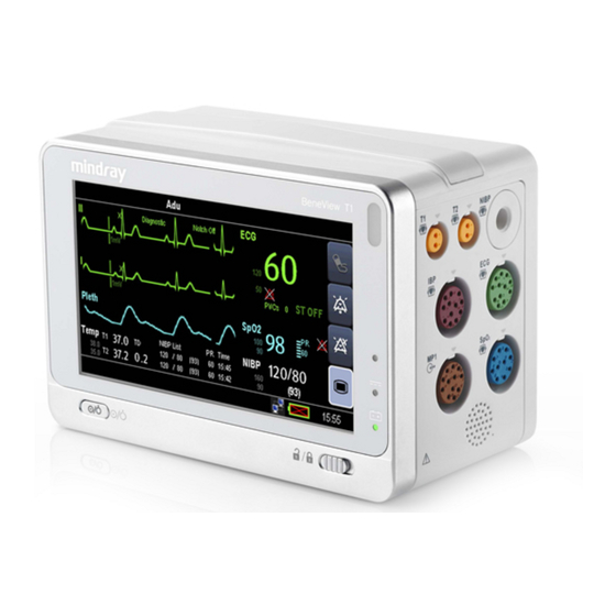
Page 36: Display Screen
2.7 Disp lay Scree This patie ent monitor ad dopts a high-res solution TFT LC CD to display pa atient paramet ters and wavefo orms. A typical display screen is shown below. Alar m Symbols Patie ent Information n/Technical Ala arm Area ... - Page 37 QuickKeys Area This area conta ains QuickKeys that give you f fast access to fu unctions. art or stop NIBP P measurement set the alarm s ystem ter alarm pause ed status ter the main m menu Prompt Messag ge Area This area show ws the current c onfiguration n...
- Page 38 FOR YOUR NOTES 2-14...
-
Page 39: Basic Operations
Basic Operations 3.1 Installation WARNING The equipment shall be installed by personnel authorized by us. The software copyright of the equipment is solely owned by us. No organization or individual shall resort to juggling, copying, or exchanging it or to any other infringement on it in any form or by any means without due permission. -
Page 40: Environmental Requirements
3.1.2 Environmental Requirements The operating environment of the equipment must meet the requirements specified in this manual. The environment where the equipment is used shall be reasonably free from noises, vibration, dust, corrosive, flammable and explosive substances. If the equipment is installed in a cabinet, sufficient space in front and behind shall be left for convenient operation, maintenance and repair. -
Page 41: Starting Monitoring
3.2.2 Starting Monitoring Decide which measurements you want to make. Check that the patient cables and sensors are correctly connected. Check that the patient settings such as [Patient Cat.], [Paced], etc, are appropriate for your patient. Refer to the appropriate measurement section for details of how to perform the measurements you require. 3.3 Turning off the Monitor Before turning off the monitor, Confirm that the patient monitoring is finished. -
Page 42: Using The External Display
Select the key to confirm what you have entered and close the onscreen keyboard. Select the to access the symbol keyboard. Select the to exit the symbol keyboard. 3.6 Using the External Display T1 can be connected to an external display through the VGA connector of the T1 docking station. When the external display is connected, you can monitor a patient either through the T1 or through the external display. -
Page 43: Using The Mouse And Keyboard
CAUTION Use only display we specify. Using unspecified display may result in unknown problem. 3.7 Using the Mouse and Keyboard When connected to the external display, T1 can connect a mouse and a keyboard through the USB connector of the T1 docking station. -
Page 44: Changing Language
You can set [Changing Bed No.] to [Unprotected]: enables you to change Bed No. in the [Patient Demographics] menu. [Protected]: disables you to change Bed No. in the [Patient Demographics] menu. 3.9.2 Changing Language Select [Main Menu]→[Maintenance >>]→[User Maintenance >>]→enter the required password. In the [User Maintenance] menu, select [Language] and then select the desired language. -
Page 45: Accessing The Parameters Menu
3.10.2 Accessing the Parameters Menu Select [Parameters >>] from the main menu or select corresponding parameter area or waveform area to access a parameter setup menu. 3.11 Operating Mode Your monitor has different operating modes. Some are password protected. This section lists the major operating modes. -
Page 46: Night Mode
3.11.3 Night Mode To avoid disturbing the patient, night mode may be used. To activate the night mode: Select [Main Menu]→[Screen Setup >>]→[Night Mode >>]. In the pop-up menu, set the desired brightness, alarm volume, QRS volume, key volume, NIBP end tone, or whether to stop NIBP measurement or not. -
Page 47: Module Mode
3.11.6 Module Mo When n T1 is connect ed to a host m onitor, it works s as the host m onitor’s param eter module. T T1 can be conne ected to the host monitor either r through the m module rack of t the host monit tor or through t... -
Page 48: Demo Mode
WARNING Do not hot plug T1 dock data cable. Hot plug may result in unknown problems. Make sure that the T1 dock data cable is disconnected from the host monitor when T1 docking station is not in use with the host monitor. 3.11.7 Demo Mode In Demo mode, the monitor can demonstrate its major functions when patient or patient simulator is not connected. -
Page 49: User Screens
User Screens 4.1 Adjusting the Screen Brightness Select the [Main Menu]→[Screen Setup >>]→[Brightness]. Select the appropriate setting for the screen brightness. 1 to 10. 10 is the brightest, and 1 is the least bright. Auto: Screen brightness will be adjusted automatically. If the patient monitor operates on battery power, you can set a less bright screen to prolong the operating time of the battery. -
Page 50: Tailoring Your Screens
4.3 Tailoring Your Screens You can tailor your patient monitor’s screens by setting: Waveform sweep mode Wave line size The color in which each measurement’s numerics and waveform are displayed The parameter to be monitored. Changing some settings may be hazardous. Therefore, those setting are password-protected and can be modified by authorized personnel only. -
Page 51: Changing Screen Layout
4.3.4 Changing Screen Layout Select [Main Menu]→[Screen Setup >>]→[Screen Layout >>] to enter the [Screens] menu. You can choose the desired screen type in the [Choose Screen] window. You can select the parameters and waveforms you want to view in the [Screen Setup] window. For details, please refer to the section Setting the Screen. -
Page 52: Understanding The Big Numerics Screen
4.4 Understanding the Big Numerics Screen To enter the big numerics screen: Select [Main Menu]→[Screen Setup >>]→[Screen Layout >>]. In the [Choose Screen] tab, select [Big Numerics]. You can select your desired parameters to display in this screen: in the [Screens] menu select [Big Numerics Screen Setup] and then select the parameters you want. -
Page 53: Viewing Oxycrg (Only Available For The External Display)
4.6 Viewing OxyCRG (only available for the external display) To have a split screen view of OxyCRG, you can select [Main Menu]→[Screen Setup >>]→[Screen Layout >>]→ [Choose Screen]→[OxyCRG Screen]→ The split-screen view covers the lower part of the waveform area and shows HR trend, SpO trend, SpO b trend, RR trend and a compressed wave (CO... -
Page 54: Viewing Other Patients (Only Available For The External Display)
4.7 Viewing Other Patients (only available for the external display) 4.7.1 Care Group You can select other patient monitors (including telemetry) connected to the same LAN into a Care Group. This lets you: View information on the monitor screen from another bed in the same Care Group. ... - Page 55 4.7.3 U Understand ding the Vi ew Other P Patient Win ndow When n you first open n the [View Oth her Patient] w window, the pat tient monitor a utomatically se elects a monito or from the netw work to display i in the [View Ot ther Patient] w window.
- Page 56 FOR YOUR NOTES...
-
Page 57: Admitting A Patient
Managin ng Patien 5.1 Ad dmitting a a Patient The p patient monito r displays phys iological data a and stores them m in the trends s as soon as a p patient is conne ected. This allow ws you to monit tor a patient th at is not admit tted yet. -
Page 58: Quick Admitting A Patient
5.2 Quick Admitting a Patient Use [Quick Admit] only if you do not have the time or information to fully admit a patient. Complete the rest of the patient demographic details later. Select [Main Menu]→[Patient Setup >>]. Select [Quick Admit]. If a patient has been admitted at present, select [OK] to discharge the current patient. If .no patient is admitted, you can choose either: ... -
Page 59: Querying From Local Facility
5.5 Querying from Local Facility You can query the patient information from either the local facility or all networked facilities. To set where to query, follow this procedure: Select [Main Menu]→[Maintenance >>]→[User Maintenance >>]→enter the required password→[Network Setup >>]→[Gateway Comm Setup >>]. Set [Query From Local Facility]. -
Page 60: Discharging A Patient
5.8 Discharging a Patient To discharge a patient: Select [Main Menu]→[Patient Setup >>]. Select [Discharge Patient]. In the popup menu, you can either: Directly select [Ok] to discharge the current patient, or Select [Standby] then [Ok]. The patient monitor enters the standby mode after discharging the current patient, or ... - Page 61 5.9.1.1 Transferring Data from the Monitor to a USB Drive Connect the T1 to the T1 docking station. Connect a USB Drive to the T1 docking station’s USB connector. Select [Main Menu] →[Patient Setup >>]. Select [Transfer to Storage Medium]. In the popup menu, select [Ok]. Wait until the following message appears: [Transfer to storage medium successful.
-
Page 62: Transferring Patient Via T1
5.9.2 Transferring Patient via T1 T1 can be used with a host monitor or the docking station to implement patient transfer. For patient transfer via the host monitor, refer to the host monitor’s operating manual for detail. NOTE Only host monitors with a system software version 05.00.00 or greater support patient transfer via T1. In the situation that T1 is in use with the docking station for patient transfer, you need to configure the docking station on T1. -
Page 63: Connecting To A Central Monitoring System
NIBP measurements, etc., bi-directional control can be achieved between your patient monitor and the CMS. NOTE Only Mindray CMS with a system software version 06.03.00 or greater supports T1. For details, refer to the CMS’s instructions for use. - Page 64 FOR YOUR NOTES 5 -8...
-
Page 65: Managing Configuration
Managing Configuration 6.1 Introduction When performing continuous monitoring on a patient, the clinical professional often needs to adjust the monitor’s settings according to the patient’s condition. The collection of all these settings is called a configuration. Allowing you to configure the monitor more efficiently, the monitor offers different sets of configuration to suit different patient categories and departments. -
Page 66: Entering The Manage Configuration Menu
6.2 Entering the Manage Configuration Menu To access configuration management, select [Main Menu]→[Maintenance >>]→[Manage Configuration >>]. Enter the required password and then select [Ok]. 6.3 Changing Department If the current department configuration is not the one you want to view, you can select [Change Department >>] in the [Manage Configuration] menu and then choose the one you want for viewing as shown below. -
Page 67: Setting Default Configuration
6.4 Setting Default Configuration The monitor will load the pre-set default configuration in the following cases. The patient monitor restarts after quitting over 120 seconds. A patient is admitted. A patient is discharged. Patient data is cleared. ... -
Page 68: Editing Configuration
6.6 Editing Configuration Select [Edit Config. >>] in the [Manage Configuration] menu. The popup menu shows the existing configurations on the monitor. Selecting [Config. on USB drive >>] will show the existing configurations on the USB drive. Select the desired configuration and then select the [Edit] button. Select [Alarm Setup >>], [Screen Setup >>] or [Parameter >>] to enter the corresponding menu in which settings can be changed. -
Page 69: Transferring A Configuration
6.8 Transferring a Configuration When installing several monitors with identical user configuration it is not necessary to set each unit separately. An USB drive may be used to transfer the configuration from monitor to monitor. To export the current monitor’s configuration: Connect a USB Drive to the T1 dock station’s USB connector. -
Page 70: Restoring The Latest Configuration Automatically
6.10 Restoring the Latest Configuration Automatically During operation, you may make changes to some settings. However, these changes may not be saved as user configuration. To prevent the changes from losing in case of a sudden power failure, the patient monitor stores the configuration in real time. -
Page 71: Alarms
Alarms Alarms, triggered by a vital sign that appears abnormal or by technical problems of the patient monitor, are indicated to the user by visual and audible alarm indications. WARNING A potential hazard can exist if different alarm presets are used for the same or similar equipment in any single area, e.g. -
Page 72: Alarm Levels
7.2 Alarm Levels By severity, the patient monitor’s alarms can be classified into three categories: high level, medium level and low level.. Physiological alarms Technical alarms High level Indicate that your patient is in a life Indicate a severe device malfunction or an improper operation, threatening situation, such as Asystole, which could make it possible that the monitor cannot detect Vfib/Vtac and so forth, and an... -
Page 73: Audible Alarm Tones
7.3.2 Audible Alarm Tones The alarm tone is distinct from heart beat tone, keystroke tone and pulse tone in frequency. This monitor has three choices of alarm tones and patterns: ISO, Mode 1 and Mode 2. For each pattern, the alarm tones identify the alarm levels as follows: ... -
Page 74: Alarm Tone Configuration
7.3.4 Flas hing Nume eric If an alarm m triggered by y an alarm limit violation occu urs, the numeric c of the measu rement in alarm m will flash eve ery second, and the c corresponding alarm limit wil l also flash at th he same freque ency indicating... -
Page 75: Changing The Alarm Tone Pattern
7.4.3 Changing the Alarm Tone Pattern To change the alarm tone pattern: Select [Main Menu] →[Maintenance >>]→[User Maintenance >>]→enter the required password. Select [Alarm Setup >>] to enter the [Alarm Setup] menu. Select [Alarm Sound] and toggle between [ISO], [Mode 1]and [Mode 2]. User or factory default configurations exert no impact on the setup of alarm tone pattern. -
Page 76: Setting The Reminder Tones
7.4.5 Setting the Reminder Tones When the alarm volume is set to zero, or the alarm is reset or switched off, the patient monitor issues a periodical reminder tone. Select [Main Menu] →[Maintenance >>]→[User Maintenance >>]→enter the required password. Select [Alarm Setup >>] to enter the [Alarm Setup] menu. Set the [Reminder Tones] to [On], [Off] or [Re-alarm]. -
Page 77: Setting Alarm Properties For All Parameters
7.5.1 Setting Alarm Properties for All Parameters In the main menu, select [Alarm Setup >>]→[Parameters]. You can review and set alarm limits, alarm switches, and alarm level for all parameters. WARNING Make sure that the alarm limits settings are appropriate for your patient before monitoring. ... - Page 78 Low alarm limit High alarm limit Module Parameter Auto alarm limits range Adult/ Adult/ Neonate Neonate pediatric pediatric (SYS – 15) or (SYS + 15) or Adult: 45 to 270 105mmHg (SYS × 0.68 + 45mmHg (SYS × 0.86 + NIBP-S Pediatric: 45 to 185 10) mmHg...
- Page 79 Low alarm limit High alarm limit Module Parameter Auto alarm limits range Adult/ Adult/ Neonate Neonate pediatric pediatric IBP: CVP/ ICP/ LAP/ RAP/ IBP-M Mean × 0.75 Mean × 0.75 Mean × 1.25 Mean × 1.25 3 to 40mmHg UVP/ P1-P4 (Venous pressure)
-
Page 80: Setting Alarm Delay Time
7.5.3 Setting Alarm Delay Time You can set the alarm delay time for over-limit alarms of continuously measured parameters. If the alarm-triggered condition disappears within the delay time, the patient monitor will not give the alarm. To set the alarm delay time, Select [Main Menu]→[Maintenance >>]→[User Maintenance >>]. -
Page 81: Entering Cpb Mode
7.5.6 Entering CPB Mode When performing Cardiopulmonary bypass (CPB), you can set the patient monitor to enter CPB mode in order to reduce unnecessary alarms. The CPB mode is activated only if you select [OR]. To select [OR], Select [Main Menu]→[Maintenance >>]→[Manage Configuration >>]. Enter the required password and then select [OK]. - Page 82 u] →[Mainten Sele ect [Main Menu nance >>]→[Us ser Maintenan nce >>]→enter r the required p password. Sele ect [Alarm Setu up >>]→[Alarm m Pause Time] ] and then sele ct the appropr iate setting fro om the popup l ist.
-
Page 83: Latching Alarms
The in ndication of ala arm lamp for th he physiologica al alarm depen nds on the alarm m light setting. When [Alarm L Light on Alarm m Reset] is set t to [On], the ala arm lamp remai ins flashing. -
Page 84: Using Care Group Alarms (Only Available For The External Display)
You can separately select [Latching Visual Signal]. Selecting [Latching Audible Signal] simultaneously latches the visual signal. Selecting alarms of lower priority simultaneously latches the alarms of higher priority. NOTE Changing of alarm priority may affect the latching status of corresponding alarm. Please determine if you need to reset the latching status for the specific alarm when you have changed its alarm priority. -
Page 85: Switching Off The Remote Device Disconnection Alarm
WARNING Resetting care group alarms may cause a potential hazard. Please act with caution. 7.10.3 Switching Off the Remote Device Disconnection Alarm The monitor can provide an alarm if a viewed bed device is disconnected. By default, the function is enabled. To disable the alarm, follow this procedure: In the current monitor, select [Main Menu]→[Maintenance>>]→[User Maintenance>>]→enter the required password→[Alarm Setup>>]→[Other Bed Alarm Setup>>]. -
Page 86: When An Alarm Occurs
7.11 T Testing Al larms The m monitor perform ms self test dur ring startup. Th he system gives s a beep, and th he alarm lamp simultaneously y turns yellow, and t then red, and fi nally off. This in ndicates that th he alarm system m functions co... -
Page 87: Monitoring Ecg
The electrocardiogram (ECG) measures the electrical activity of the heart and displays it on the patient monitor as a waveform and a numeric. ECG monitoring provides the following algorithms: Mindray algorithm: provides 3-, 5-, and 12-lead ECG monitoring, ST-segment analysis, arrhythmia analysis. Mortara algorithm: provides 3-, 5-, and 12-lead ECG monitoring, ST-segment analysis, arrhythmia analysis. -
Page 88: Preparing To Monitor Ecg
NOTE After defibrillation, the screen display recovers within 10 seconds if the correct electrodes are used and applied in accordance with the manufacturer’s instructions for use. 8.3 Preparing to Monitor ECG 8.3.1 Preparing the Patient and Placing the Electrodes Prepare the patient’s skin. - Page 89 5-Leadwire Electrode Placement Following is an electrode configuration when using 5 leadwires: RA placement: directly below the clavicle and near the right shoulder. LA placement: directly below the clavicle and near the left shoulder. RL placement: on the right lower abdomen. ...
-
Page 90: Checking Paced Status
WARNING When using an electrosurgery unit (ESU), ensure proper contact of the ESU's return electrode to the patient to avoid burns at the monitor measurement site. Never entangle the ESU cable and the ECG cable together. The neutral electrode of the electrosurgical unit shall properly contact the patient. Otherwise, burns may result. -
Page 91: Understanding The Ecg Display
8.4 Understanding the ECG Display Your display may be configured to look slightly different. Lead label of the displayed wave ECG gain ECG filter label Notch filter status Besides, when a paced signal has been detected, the pace pulse marks “|” are shown on the ECG wave if the [Paced] has been set to [Yes]. -
Page 92: Choosing The Alarm Source
8.5.2 Choosing the Alarm Source In most cases the HR and PR numerics are identical. In order to avoid simultaneous alarms on HR and PR, the monitor uses either HR or PR as its active alarm source. To change the alarm source, select [Alm Source] in the [ECG Setup] menu and then select either: ... -
Page 93: Setting Pacemaker Rate (For Mortara Only)
8.5.5 Setting Pacemaker Rate (For Mortara only) Some pacemaker pulses can be difficult to reject. When this happens, the pulses are counted as a QRS complex and could result in an incorrect HR and failure to detect some arrhythmias. You can set [Pacemaker Rate] to the pacemaker’s rate in the [ECG Setup] menu. -
Page 94: Adjusting The Minimum Qrs Detection Threshold (For Mindray Ecg Algorithm)
When [Paced] is set to [No], the pace markers are not shown on the ECG wave, and the options of [Pacer Reject] are inactivated. 8.5.9 Adjusting the Minimum QRS Detection Threshold (For Mindray ECG Algorithm) To avoid false asystole alarms when the R wave amplitude is low and missed asystole alarms during ventricular standstill (tall P waves, but no QRS), a means to manually adjust the minimum QRS detection threshold is provided. -
Page 95: About The Defibrillator Synchronization
8.5.13 About the Defibrillator Synchronization If a defibrillator is connected, a defibrillator synchronization pulse (100 ms, +5V) is outputted through the multifunctional Connector every time when the patient monitor detects an R-wave. WARNING Improper use of a defibrillator may cause injury to the patient. The user should determine whether to perform defibrillation or not according to the patient’s condition. -
Page 96: Changing St Filter Settings
8.6.2 Changing ST Filter Settings ST-segment analysis can be carried out only when the filter mode is set to [Diagnostic] or [ST]. When ST-segment analysis is switched on, [Filter] will automatically switch to [ST] if it is not [Diagnostic] or [ST]. When ST-segment analysis is switched off, the filter mode automatically switches to previous manual setting. -
Page 97: Saving The Current St Segment As Reference
8.6.4 Saving the Current ST Segment as Reference Select [Save Ref.] in the [ST Analysis] menu to save the current segment as reference. Up to 20 reference segment groups can be saved. NOTE If the memory is full and you do not delete a group before saving a new one, the oldest saved group is deleted automatically. -
Page 98: Adjusting St Measurement Points
8.6.9 Adjusting ST Measurement Points As shown in the figure below, the ST measured for each beat complex is the vertical difference between two measurement points with the R-wave peak as the baseline for the measurement. R-wave peak J point Difference=ST value ST measurement point Isoelectric point... -
Page 99: Qt/Qtc Interval Monitoring (For Mindray Ecg Algorithm)
8.7 QT/QTc Interval Monitoring (For Mindray ECG Algorithm) The QT interval is defined as the time between the beginning of the Q-wave and the end of the T-wave. It measures the total duration of the depolarization (QRS duration) and repolarization (ST-T) phases of the the ventricles. QT interval monitoring can assist in the detection of long QT syndrome. -
Page 100: Enabling Qt/Qtc Monitoring
8.7.2 Enabling QT/QTc Monitoring The QT monitoring function is disabled by default. Before you start QT monitoring, enable the QT function. To enable QT/QTc monitoring: In the [ECG Setup] menu, select [QT Analysis>>] to enter the [QT Analysis] menu. Set [QT Analysis] to [On]. 8.7.3 Displaying QT/QTc Parameters and Waveform To display QT/QTc parameters and waveform: Select [Main Menu] →[Screen Setup>>]→[Screen Layout>>], and then select [Screen Setup] to enter the... -
Page 101: Entering The Qt View
8.7.4 Entering the QT View QT View shows the current and reference QT parameter values and waveforms. To enter the QT View: Select the QT parameter area or waveform area to enter the [QT Analysis] menu. Select [QT View>>]. The following picture shows the QT view. ... -
Page 102: Changing Qt Settings
8.7.6 Changing QT Settings 8.7.6.1 Setting QT Alarm Properties To set QT alarm properties, Select [Alarm Setup>>] from the [QT Analysis] menu. Set QTc and ΔQTc alarm properties. 8.7.6.2 Selecting Leads for QT Calculation You can select one lead or all leads for QT calculation. To do so, select [Analysis Lead] from the [QT Analysis] menu. [All] is selected by default. -
Page 103: About Arrhythmia Monitoring
Atrial fibrillation (Afib) detection function is not intended for pediatric and neonatal patients. Mortara arrhythmia algorithm is not intended for neonatal patients. 8.8.1 Understanding the Arrhythmia Events Mindray algorithm Arrhythmia message Description Category No QRS detected within the set time threshold in absence of ventricular Asystole fibrillation or chaotic signal. - Page 104 Arrhythmia message Description Category Tachy The average heart rate is equal to or greater than the tachycardia limit. The consecutive PVCs ≥ the Vbrd PVCs limit, and the HR ≥ Vbrd Rate Vent. Rhythm limit but < the Vtac Rate limit. Multif.
-
Page 105: Changing Arrhythmia Alarm Settings
In case an arrhythmia violates its threshold, an alarm will be triggered. The asystole delay time relates to ECG relearning. When HR is less than 30 bpm, it is recommended to set the asystole delay time to 10 seconds. Mindray algorithm Arrh. event Range... -
Page 106: Setting The Extended Arrh. (For Mindray Algorithm Only)
Pediatric: 160 Brady Low Adult: 15 to 60 Adult: 60 Pediatric: 15 to 80 Pediatric: 80 8.8.4 Setting the Extended Arrh. (For Mindray Algorithm Only) The following arrhythmia events are defined as extended arrhythmia: Extreme Tachy Extreme Brady ... -
Page 107: Ecg Relearning
8.9 ECG Relearning 8.9.1 Initiating an ECG Relearning Manually During ECG monitoring, you may need to initiate an ECG relearning when the patient’s ECG template changes dramatically. A change in the ECG template could result in: incorrect arrhythmia alarms ... -
Page 108: 12-Lead Ecg Monitoring
8.10 12-Lead ECG Monitoring 8.10.1 Entering the 12-lead ECG Monitoring Screen Refer to the section 8.3.3 ECG Lead Placements to place the electrodes. In the [ECG Setup] menu, select [Others>>] to enter the [Others Setup Menu]. Set [Lead Set] to [12-Lead], set [ECG Display] to [12-Lead]. There are totally 12 ECG waves and 1 rhythm wave displayed on the screen. -
Page 109: Resting 12-Lead Ecg Analysis
8.11 Resting 12-lead ECG Analysis 8.11.1 Entering the 12-lead Screen In the [ECG Setup] menu, select [Others>>] to enter the [Other Setup Menu]. Set [Lead Set] to [12-Lead]. Set [ECG Display] to [12-Lead]. The functions of the keys at the bottom of the 12-lead screen are as follows: [Analyze]: starts resting 12-lead analysis. -
Page 110: 12-Lead Setup
8.11.3 12-Lead Setup In the 12-lead screen, select [Setup] to enter the [12-Lead Setup] menu to change the settings related to 12-lead ECG analysis. In the [12-Lead Setup] menu, you can also select [Report Setup>>] to set the format and contents of the ECG reports. - Page 111 HeartRate Fridericia: HeartRate Framingham: Waveform Layout Standard, Cabrera Standard Select ECG lead sequence for displaying and printing. [Standard]: the sequence is I, II, III, aVR, aVL, aVF, V1, V2, V3, V4, V5, V6.
-
Page 112: Resting 12-Lead Ecg Analysis
8.11.4 Resting 12-lead ECG Analysis The Glasgow algorithm provides an interpretation of the resting 12-lead ECG in all situations. Before 12-lead ECG interpretation, check that all electrodes are correctly connected to the lead wires and the ECG trunk cable is properly connected. Check that patient information is correct. To start analyzing, select the [Analyze] key. -
Page 113: 12-Lead Ecg Report
8.11.5 12-lead ECG Report The following is a sample of the12-lead ECG report with default configuration. Patient information Time of resting 12-lead ECG analysis Measurements Diagnosis statement Waveform amplitude Paper speed Frequency range System software version/algorithm version 8-27... -
Page 114: Troubleshooting
8.12 Troubleshooting This section lists the problems that might occur. If you encounter the problems when using the equipment or accessories, check the table below before requesting for services. If the problem persists, contact your service personnel. CAUTION Never try to disassemble the equipment or supplied accessories. There are no internal user-serviceable parts. - Page 115 Symptoms Possible Cause Correction Action Changing ECG Wave Settings. Lead wires and patient cable not fully Check that the leadwires and patient cables are or properly inserted properly connected. Cable or lead wires damaged Change cable and lead wires. Base Line Wander Patient moving excessively Secure leadwires and cable to patient.
- Page 116 FOR YOUR NOTES 8-30...
-
Page 117: Monitoring Respiration (Resp)
Monitoring Respiration (Resp) 9.1 Introduction Impedance respiration is measured across the thorax. When the patient is breathing or ventilated, the volume of air changes in the lungs, resulting in impedance changes between the electrodes. Respiration rate (RR) is calculated from these impedance changes, and a respiration waveform appears on the patient monitor screen. -
Page 118: Placing Resp Electrodes
9.4 Placing Resp Electrodes As the skin is a poor conductor of electricity, preparing the skin is necessary for a good Respiration signal. You can refer to the ECG section for how to prepare the skin. As the Respiration measurement adopts the standard ECG electrode placement, you can use different ECG cables (3-lead, 5-lead or 12-lead). -
Page 119: Lateral Chest Expansion
9.4.4 Lateral Chest Expansion In clinical applications, some patients (especially neonates) expand their chests laterally, causing a negative intrathoracic pressure. In these cases, it is better to place the two respiration electrodes in the right midaxillary and the left lateral chest areas at the patient’s maximum point of the breathing movement to optimise the respiratory waveform. -
Page 120: Setting Rr Source
9.8 Chan nging Res sp Wave S Settings ARNING en monitoring g in manual de etection mode e, make sure to o check the res spiration dete ection leve el after you ha ave increased o or decreased t the size of the e respiration w wave. -
Page 121: Monitoring Pr
Monitoring PR 10.1 Introduction The pulse numeric counts the arterial pulsations that result from the mechanical activity of the heart. You can display a pulse from any measured SpO or any arterial pressure (see 14 Monitoring IBP). The displayed pulse numeric is color-coded to match its source. -
Page 122: Selecting The Active Alarm Source
10.3 Selecting the Active Alarm Source In most cases the HR and pulse numerics are identical. In order to avoid simultaneous alarms on HR and Pulse, the monitor uses either HR or Pulse as its active alarm source. To change the alarm source, select [Alm Source] in the [ECG Setup] or [SpO2 Setup] menu and then select either: ... -
Page 123: Monitoring Spo
Above 1 is optimal, between 0.3 and 1 is acceptable. Below 0.3 indicates low perfusion; reposition the SpO2 sensor or find a better site. If low perfusion persists, choose another method to measure oxygen saturation if possible. PI is available for Mindray SpO module and Masimo SpO module. -
Page 124: Safety
11.3 Ide ntifying S dules The mon itor can be con nfigured with M Mindray SpO module, Masimo o SpO module e, or Nellcor SpO module. To identify which Sp module is in... -
Page 125: Changing Spo Settings
To set the averaging time: Sensitivity SpO2 Setup High For Mindray SpO module, select [ ] in the [ ] menu and then toggle between [ ] and [ ], which respectively correspond to 7 s, 9 s and 11 s. - Page 126 management. A Sat-Seconds limit is also set. The Sat-Seconds limit controls the amount of time that SpO saturation may be outside the set limits before an alarm sounds. The method of calculation is as follows: the number of percentage points that the SpO saturation falls outside the alarm limit is multiplied by the number of seconds that it remains outside the limit.
-
Page 127: Changing The Speed Of The Pleth Wave
11.5.6 Changing the Speed of the Pleth Wave SpO2 Setup Sweep In the [ ] menu, select [ ] and then select the appropriate setting. The faster the waveform sweeps, the wider the waveform is. 11.5.7 Setting the Alarm Level for SpO Sensor Off Alarm Alarm Setup >>... -
Page 128: Masimo Information
11.7 Masimo Information Masimo Patents This device is covered under one or more the following U.S.A. patents: 5,758,644, 6,011,986, 6,699,194, 7,215,986, 7,254,433, 7,530,955and other applicable patents listed at: www.masimo.com/patents.htm. No Implied License Possession or purchase of this device does not convey any express or implied license to use the device with unauthorized sensors or cables which would, alone, or in combination with this device, fall within the scope of one or more of the patents relating to this device. - Page 129 11.9 T Troublesh hooting This s section lists the e problems tha t might occur. If you encount ter the problem ms when using t the equipment t or acces ssories, check t he table below w before reques sting for service es.
- Page 130 FOR YOUR NOTES 11-8...
-
Page 131: Monitoring Nibp
Monitoring NIBP 12.1 Introduction The patient monitor uses the oscillometric method for measuring the non-invasive blood pressure (NIBP). This measurement can be used for adults, pediatrics and neonates. Automatic non-invasive blood pressure monitoring uses the oscillometric method of measurement. To understand how this method works, we’ll compare it to the auscultative method. -
Page 132: Safety
12.2 Safety WARNING Be sure to select the correct patient category setting for your patient before measurement. Do not apply the higher adult settings for pediatric or neonatal patients. Otherwise it may present a safety hazard. Do not measure NIBP on the limb where skin damage has occurred or is expected. ... -
Page 133: Setting Up The Nibp Measurement
12.5 Setting Up the NIBP Measurement 12.5.1 Preparing the Patient In normal use, perform NIBP measurement on a patient who is in the following position: Comfortably seated Legs uncrossed Feet flat on the floor Back and arm supported ... - Page 134 12.5.4 Cor rrecting the e Measurem ment if Lim mb is not at Heart Leve The cuff s should be appl lied to a limb a t the same leve el as the patien nt’s heart. If the limb is not at t the heart level, , to the displayed...
-
Page 135: Sequence Measurement
WARNING Continuous non-invasive blood pressure measurements may cause purpura, ischemia and neuropathy in the limb with the cuff. Inspect the application site regularly to ensure skin quality and inspect the extremity of the cuffed limb for normal color, warmth and sensitivity. If any abnormity occurs, move the cuff to another site or stop the blood pressure measurements immediately. -
Page 136: Understanding The Nibp Numerics
12.6 Understanding the NIBP Numerics The NIBP display shows numerics only as below. Your display may be configured to look slightly different. Systolic pressure Diastolic pressure Mean pressure obtained after the measurement and cuff pressure obtained during the measurement If the NIBP measurement exceeds the measurement range, “---” will be displayed. 12.7 Changing NIBP Settings By selecting the NIBP parameter window, you can enter the [NIBP Setup] menu. -
Page 137: Switching On Nibp End Tone
12.7.5 Switching On NIBP End Tone The monitor can issue a reminder tone at the completion of NIBP measurement. The NIBP End Tone is off by default. You can switch it on by accessing the [NIBP Setup] menu. 12.8 Assisting Venous Puncture You can use the NIBP cuff to cause sub-diastolic pressure to block the venous blood vessel and therefore help venous puncture. - Page 138 FOR YOUR NOTES 12-8...
-
Page 139: Monitoring Temp
Monitoring Temp 13.1 Making a Temp Measurement This monitor can simultaneously monitor two temperature sites. Verify that the probe detection program works correctly before monitoring. Plug out the temperature probe cable from the T1 or T2 connector, and the monitor can display the message [T1 Sensor Off] or [T2 Sensor Off] and give alarm tones correctly. - Page 140 FOR YOUR NOTES 13-2...
-
Page 141: Monitoring Ibp
Monitoring IBP 14.1 Introduction The monitor can monitor two invasive blood pressures and displays the systolic, diastolic and mean pressures and a waveform for each pressure. 14.2 Safety WARNING Use only pressure transducers specified in this manual. Never reuse disposable pressure transducers. ... -
Page 142: Measuring An Invasive Blood Pressure
14.3 Measuring an Invasive Blood Pressure 14.3.1 Setting Up the Pressure Measurement Plug the pressure cable into the IBP connector. Prepare the flush solution. Flush the system to exhaust all air from the tubing. Ensure that the transducer and stopcocks are free of air bubbles. WARNING ... -
Page 143: Zeroing The Transducer
14.3.2 Zeroing the Transducer To avoid inaccurate pressure readings, the monitor requires a valid zero. Zero the transducer in accordance with your hospital policy (at least once per day). Zero whenever: A new transducer or adapter cable is used. You reconnect the transducer cable to the monitor. The monitor restarts. -
Page 144: Measuring Icp Using The Codman Icp Transducer
14.4 Measuring ICP Using the Codman ICP Transducer 14.4.1 Zeroing the Codman ICP transducer You shall zero the Codman ICP transducer (PN: 040-002336-00) before use. To zero the ICP transducer, follow this procedure: Before unpacking the ICP transducer, check that the monitor supports the Codman ICP transducer. a. -
Page 145: Understanding The Ibp Display
Connect the ICP adapter cable, measurement module, and the target monitor, or insert the measurement module into the target monitor. Check that the zero reference value displayed on the monitor is consistent with that recorded on the ICP transducer. Consistent: select [Accept]. Inconsistent: input the zero reference value recorded on the ICP transducer, and select [Accept]. -
Page 146: Setting The Pressure Label Order
Note When two pressures are deteted having the same label, the patient monitor changes one pressure label to a currently unused one. 14.6.2 Setting the Pressure Label Order Select [IBP Label Order Setup >>] from the parameter setup menu to set the display order of the pressure labels. The default display order is: Art, pArt, CVP, pCVP, ICP, PA, Ao, UAP, FAP, BAP, LV, LAP, RAP, UVP, P1, P2, P3, P4. -
Page 147: Enabling Ppv Measurement And Setting Ppv Source
14.6.6 Enabling PPV Measurement and Setting PPV Source PPV indicates pulse pressure variation. To enable PPV measurement, set [PPV Measurement] to [On] You can select PPV source when PPV measurement is enabled. WARNING This monitor can calculate PPV from beat-to-beat values of any arterial pulsatile pressure. The circumstances under which the calculation of a PPV value is clinically meaningful, appropriate and reliable must be determined by a physician. -
Page 148: Overlapping Ibp Waveforms
14.7 Overlapping IBP Waveforms The IBP waveforms can be displayed together. To combine IBP waveforms, Select [Main Menu]→[Screen Setup>>]→[Screen Layout>>] to access the [screens] window. Select the [Screen Setup] tab. In Area A, select [IBP Overlap] from the drop-down list, and then select the IBP waves to be overlapped on the left side of the same line. -
Page 149: Measuring Pawp (Only Available For The External Display)
14.8 Measuring PAWP (only available for the external display) Pulmonary Artery Wedge Pressure (PAWP) values, used to assess cardiac function, are affected by fluid status, myocardial contractility, and valve and pulmonary circulation integrity. Obtain the measurement by introducing a balloon-tipped pulmonary artery flotation catheter into the pulmonary artery. When the catheter is in one of the smaller pulmonary arteries, the inflated balloon occludes the artery allowing the monitor to record changes in the intrathoracic pressures that occur throughout the respiration cycle. - Page 150 14.8.1 Pre eparing to Measure P PAWP onnect the cath heter and trans ducer as shown n below. Make sure that: The PA cath heter is in place e in the patient The IBP tran nsducer is prop perly connected d to the IBP co nnector on the...
-
Page 151: Setting Up The Pawp Measurement
14.8.2 Setting Up the PAWP Measurement Select [Start] in the PAWP measurement window. Wedge the flotation catheter into the pulmonary artery. When the prompt message [Ready for balloon inflation] appears, inflate the balloon and pay attention to PA waveform changes on the screen. When the prompt message [Ready for balloon deflation] appears, deflate the balloon. -
Page 152: Performing Hemodynamic Calculation
14.8.4 Performing Hemodynamic Calculation In the PAWP window, select [Calc.>>] to enter the hemodynamic calculation menu. Refer to 18.5 Hemodynamic Calculations for details. 14.9 Troubleshooting This section lists the problems that might occur. If you encounter the problems when using the equipment or accessories, check the table below before requesting for services. -
Page 153: Monitoring Carbon Dioxide
Monitoring Carbon Dioxide 15.1 Introduction monitoring is a continuous, non-invasive technique for determining the concentration of CO in the patient’ airway by measuring the absorption of infrared (IR) light of specific wavelengths. The CO has its own absorption characteristic and the amount of light passing the gas probe depends on the concentration of the measured CO When a specific band of IR light is passed through respiratory gas samples, some of IR light will be absorbed by the CO molecules. -
Page 154: Identifying Co Modules
15.2 Identifying CO Modules This monitor uses an external module to perform CO monitoring. From left to right are sidestream CO module, microstream CO module and mainstream CO Setup key to enter the CO setup menu Measure/standby Gas outlet watertrap seat Connector for sampling line Connector for CO transducer... -
Page 155: Preparing To Measure Co2
15.3 Preparing to Measure CO2 WARNING Eliminate the exhausted gas before performing the measurement. Check that the alarm limit settings are appropriate before taking measurement. NOTE Perform the measurement in a well-ventilated environment. 15.3.1 Using a Sidestream CO Module Attach the watertrap to the module and then connect the CO components as shown below. -
Page 156: Using A Microstream Co 2 Module
NOTE To extend the lifetime of the watertrap and module, disconnect the watertrap and set the operating mode to standby mode when CO monitoring is not required. 15.3.2 Using a Microstream CO Module Connect the sampling line to the module and then connect the CO components as shown below. -
Page 157: Changing Co 2 Settings
NOTE Always position the sensor with the adapter in an upright position to avoid collection of fluids on the windows of the adapter. Large concentrations of fluids at this point will obstruct gas analysis. 15.4 Changing CO Settings 15.4.1 Setting the CO Unit Select [Unit Setup >>] from the [User Maintenance] menu. -
Page 158: Setting Up Humidity Compensation
15.4.4 Setting up Humidity Compensation Sidestream and microstream CO modules are configured to compensate CO readings for either Body Temperature and Pressure, Saturated Gas (BTPS), to account for humidity in the patient’s breath, or Ambient Temperature and Pressure, Dry Gas (ATPD). ... -
Page 159: Setting The Flow Rate
15.4.7 Setting the Flow Rate For the sidestream CO module, you can change the sampling rate of respiratory gas in the patient’s airway by setting the flow rate. To set the flow rate, enter the [CO2 Setup] menu and select an appropriate setting from [Flow Rate]. WARNING ... -
Page 160: Entering The Standby Mode
15.4.11 Entering the Standby Mode By default, the CO module is in measure mode. To enter or exit the standby mode manually, select [Operating Mode] in the [CO2 Setup] menu and then toggle between [Standby] and [Measure]. The standby mode of the CO module relates to the standby mode of the monitor as follows: If the monitor enters the standby mode, the CO2 module will also enter the standby mode. -
Page 161: Troubleshooting The Sidestream Co Sampling System
15.7 Troubleshooting the Sidestream CO Sampling System When the sampling system of the sidestream CO module works incorrectly, check if the sampling line is kinked. If not, remove it from the watertrap. If the monitor gives a message indicating the airway still works incorrectly, it indicates that the watertrap must have been blocked, and you should replace with a new one. -
Page 162: Calibrating The Sensor
Select [Start Zero Cal.] in the [CO2 Setup] menu. The message [CO2 Zero Running] is displayed. Zero calibration takes about 15 to 20 seconds. The message disappears when the zero calibration is completed. WARNING When perform a zero calibration during the measurement, disconnect the transducer from the patient’s airway first. -
Page 163: Monitoring Cco
Monitoring CCO 16.1 Introduction The monitor uses PiCCO method to perform CCO monitoring. The PiCCO method combines transpulmonary thermodilution and pulse contour analysis on the blood pressure waveform. A cold bolus (e.g. normal saline 0.9%) with a known volume and temperature is injected into the right atrium through a central venous catheter. -
Page 164: Zeroing The Transducer
16.3 Zeroing the Transducer To avoid inaccurate pressure readings, the monitor requires a valid zeroing. Zero the transducer in accordance with your hospital policy (at least once per shift). Zero whenever: A new transducer or adapter cable is used. ... -
Page 165: Preparation For Cco Monitoring
16.4 Preparation for CCO Monitoring Please refer to the following figure and procedure to set up the CCO monitoring: Arterial thermodilution catheter Blood temperature sensor Central venous catheter PiCCO cable Injectate temperature sensor cable Injectate temperature sensor IBP cable Arterial pressure transducer CVP transducer Place the arterial thermodilution catheter. - Page 166 WARNING If air bubbles appear in the tubing system, flush the system with the infusion solution again. Air bubble may lead to wrong pressure reading. Connect one end of the CVP transducer to the central venous catheter and the other end to the IBP cable marked with pCVP (neglect this procedure if CVP measurement is not performed).
-
Page 167: Performing Cco Monitoring And Cco Calibration
ELWI < 10 ELWI > 10 ELWI < 10 Patient Weight (kg) Iced Injectate Iced Injectate Room Temperature Injectate <3 <10 <25 <50 10ml 10ml <100 10ml 15ml 15ml ≥100 15ml 20ml 20ml 11. Set up the C.O. measure mode by selecting [C.O. Measure] from the [CCO Setup] menu, and toggling between [Auto] and [Manual]. - Page 168 Select the [Start] button and inject the bolus rapidly (<7sec) and smoothly as soon as the message [Inject xx ml!] and prompt tone appear. As shown in the figure above, during the measurement, the currently measured thermodilution curve is displayed. At the end of the measurement, the measured values are displayed in the history window and the monitor prompts you to wait for a certain period of time before starting a new measurement.
-
Page 169: Understanding The Displayed Cco Parameters
16.6 Understanding the Displayed CCO Parameters 16.6.1 Understanding the CCO Display Prompt message area Label and value for main parameter Labels and values for secondary parameters 16.6.2 Understanding the pArt Display The artery pressure is displayed on the monitor as a waveform and numeric pressures. The figure below shows the pArt waveform and numerics. -
Page 170: Hemodynamic Parameters
16.7 Hemodynamic Parameters You can enter the [Hemodynamic Parameters] menu by accessing the [CCO Setup] menu and selecting [Hemo Para.>>]. 16.8 Hemodynamic Parameters(only available for the external display) 16.8.1 Spider Vision 16.8.1.1 Spider Vision Diagram The spider vision diagram shows all continuous parameters in dynamic conjunction. Each spider leg is divided into 3 segments indicating different value ranges for the respective parameters. - Page 171 The diagram is displayed YELLOW immediately when one of the displayed parameters goes outside the normal range. The diagram appears RED when two or more displayed parameters are outside the normal range. The parameter whose default normal range is changed will be marked with the symbol 16.8.1.2 Spider Configuration The spider vision diagram can be configured individually.
-
Page 172: Hemodynamic Parameters
16.8.2 Hemodynamic Parameters Select [Hemodynamic Parameters] tab from the [Hemodynamic Parameters] menu to view the patient’s hemodynamic parameters. In the [Hemodynamic Parameters] menu, you can select [Range] to view the referential normal range of each parameter. If a parameter value exceeds its normal range, the system will add a “↑” or “↓” to the right of the parameter. -
Page 173: Changing Cco Settings
Abbreviation Full Spelling Unit Default Normal Range ELWI Extravascular Lung Water Index ml/kg 3.0-7.0 Cardiac Power Output Cardiac Power Index W/ m 0.5-0.7 Pulmonary Vascular Permeability PVPI no unit 1.0-3.0 Index Blood Temperature ºC 16.9 Changing CCO Settings 16.9.1 Selecting the Displayed Parameters Select [Select Parameter>>] from the [CCO Setup] menu. - Page 174 FOR YOUR NOTES 16-12...
-
Page 175: Review
Review 17.1 Accessing Respective Review Windows Select [Main Menu]→[Review >>]. Then select [Graphic Trends], [Tabular Trends], [Events], or [Full Disclosure] to access their respective review windows. 17.2 Reviewing Graphic Trends In the [Review] menu, select [Graphic Trends] to access the following window. Event mark area Time axis Graphic trends area... -
Page 176: Reviewing Tabular Trends
A time indicating your current position is displayed above the parameter area. Numeric measurement values corresponding to the cursor location change as the cursor is moved. The measurement value that triggered high level alarm has red background. The one that triggered medium/low level alarm has yellow background. By selecting beside [Event], you can position the cursor to different event time. -
Page 177: Reviewing Events
To browse the tabular trends, you can select to scroll left or right to navigate through the trend database. The measurement value that triggered high level alarm has red background. The one that triggered medium/low level alarm has yellow background. By selecting beside [Event], you can position the cursor to different event time. - Page 178 After selecting the desired event, you can select [Details] to access the following window. In this window, the waveform area displays the waveforms related to the event, and the parameter area displays the parameter values happened at the event trigger time. NOTE Pausing or switching off alarms will not be recorded as events.
-
Page 179: Reviewing Waveforms
17.5 Reviewing Waveforms In the [Review] menu, select [Full Disclosure] to access the following window. To review full-disclosure waveforms, you need to save waveforms first. Select [Save Waves >>] and then select the parameters whose waveforms you want to view. To save full-disclosure waveform, your monitor must be equipped with a SD storage card. - Page 180 After selecting the [Details] button, you can access the following window. In this window, the waveform area displays the trends and waveform of the OxyCRG, and the parameter area displays the parameter values happened at the event trigger time. A. Waveform area B.
-
Page 181: Calculations
Calculations 18.1 Introduction The calculation feature is available with your patient monitor. The calculated values, which are not directly measured, are computed based on the values you provide. Your can perform the following calculations: Dose calculations Oxygenation calculations ... -
Page 182: Dose Calculations
18.2 Dose Calculations 18.2.1 Performing Calculations To perform a dose calculation: Select [Main Menu]→[Calculations >>]→[Dose >>], or select [Calculations] QuickKey→[Dose >>]. Select, in turn, [Patient Cat.] and [Drug Name] and then select the appropriate settings. The dose calculation program has a library of commonly used drugs, of which Drug A through Drug E are for those not specified in this library. -
Page 183: Titration Table
18.2.3 Titration Table To open the titration table, select [Titration Table >>] in the [Dose Calculation] window after the dose calculation is finished. In the titration table, when you change: [Reference] [Interval] [Dose Type] The titrated values change accordingly. You can also: ... -
Page 184: Entered Parameters
In the [Oxygenation Calculation] window, you can: Change the pressure unit, Hb unit and oxygen content unit by selecting [Press. Unit], [Hb Unit] and [OxyCont Unit] and then selecting the appropriate settings. The changes take effect automatically. Trigger a recording by selecting the [Record] button. The currently displayed oxygenation calculations are printed out by the recorder. -
Page 185: Ventilation Calculations
18.4 Ventilation Calculations 18.4.1 Performing Calculations To perform a ventilation calculation: Select [Main Menu]→[Calculations >>]→[Ventilation >>], or select [Calculations] QuickKey→ [Ventilation >>]. Enter values for calculation. If the patient monitor is connected to an anesthesia machine or a ventilator, the system automatically loads the supported parameter values to the [Ventilation Calculation] window. -
Page 186: Calculated Parameters And Formulas
18.4.3 Calculated Parameters and Formulas Abbreviation Unit Full spelling Formula /100 -PaCO (ATMP-47) × FiO × [FiO mmHg partial pressure of oxygen in the alveoli /100 + (1-FiO /100) / RQ ] - PaO AaDO mmHg alveolar-arterial oxygen difference Pa/FiO mmHg oxygenation ratio 100 ×... -
Page 187: Entered Parameters
18.5.2 Entered Parameters Abbreviation Unit Full spelling C.O. L/min cardiac output heart rate PAWP mmHg pulmonary artery wedge pressure Art Mean mmHg artery mean pressure PA Mean mmHg pulmonary artery mean pressure mmHg central venous pressure end-diastolic volume Height height Weight weight 18.5.3 Calculated Parameters and Formulas... -
Page 188: Renal Calculations
18.6 Renal Calculations 18.6.1 Performing Calculations To perform a renal calculation: Selecting [Main Menu]→[Calculations >>]→[Renal >>], or select [Calculations] QuickKey→[Renal >>]. Enter values for calculation. Select the [Calculate] button. The system performs a calculation per the current settings and displays the calculated values. -
Page 189: Calculated Parameters And Formulas
18.6.3 Calculated Parameters and Formulas Abbreviation Unit Full spelling Formula URNaEx mmol/24h urine sodium excretion Urine × URNa / 1000 URKEx mmol/24h urine potassium excretion Urine × URK / 1000 Na/K sodium potassium ratio 100 × URNa / URK ml/24h clearance of sodium URNa ×... - Page 190 FOR YOUR NOTES 18-10...
-
Page 191: Printing
Printing 19.1 Printer The monitor can output patient reports via a connected printer. So far, the monitor supports the following printer: HP LaserJet 1505n HP LaserJet P2035n HP LaserJet P4015n HP LaserJet Pro 400 M401n HP LaserJet 600 M602 ... -
Page 192: Starting Report Printouts
19.4 Starting Report Printouts Reports Contents Procedures ECG reports ECG waveforms and relevant Select [Main Menu]→[Print Setup >>]→[ECG Reports >>]→ parameter values [Print] Tabular Depend on the selected Select [Main Menu]→[Print Setup >>]→[Tabular Trends trends parameter group, resolution and Reports >>]→[Print], or select [Main Menu]→[Review >>]→ time period [Tabular Trends]→[Print]→[Print] Graphic... -
Page 193: Setting Up Tabular Trends Reports
19.6.2 Setting Up Tabular Trends Reports To set up tabular trends reports, select [Main Menu]→[Print Setup >>]→[Tabular Trends Reports >>]. Start time: You can set a time period whose trend data will be printed out by setting [From] and [Back]. For example, if you set [From] as 2007-4-2 10:00:00 and [Back] as [2 h], the outputted data will be from 2007-4-2 08:00:00 to 2007-4-2 10:00:00. -
Page 194: End Case Reports
19.7 End Case Reports ECG reports, tabular trends reports, graphic trends reports, NIBP review reports and realtime reports can be set as end case reports. When you discharge a patient, the system will automatically print out all contents that are set as end case reports. -
Page 195: Other Functions
Other Functions 20.1 Analog Output The monitor is configured with a multifunction connector for analog output. You can contact your service personnel for more details. 20.2 Exporting the Log The monitor stores system status information, including failures, abnormity, and technical alarms, into the log. You can export the log to a USB drive. -
Page 196: Transferring Data By Different Means
20.3.2 Transferring Data by Different Means NOTE Never enter the data transfer mode when the patient monitor is in normal operation or performs monitoring. You must re-start the patient monitor to exit the data transfer mode. Transfer data via a crossover network cable Before transferring data using a crossover network cable, do as follows: Connect the T1 to the T1 docking station. -
Page 197: Network Connection
20.4 Network Connection 20.4.1 Setting the Monitor Network The patient monitor supports both wired and wireless network. To set the monitor network: Select [Main Menu]→[Maintenance>>]→[User Maintenance>>]→enter the required password→[Network Setup >>]→[Monitor Network Setup >>]. In the Monitor Network Setup menu, set the [Network Type] or [Address Type]. The network type can be set to [WLAN] or [LAN]. -
Page 198: Wlan Setup
20.4.4 WLAN Setup To set the properties of wireless network, follow this procedure: Select [Main Menu]→[Maintenance>>]→[User Maintenance>>]→enter the required password→[Network Setup >>]→[WLAN Setup >>]. Set [WLAN Band], [Aut. Server Type], [BG Channel] and [A Channel] WLAN band can be set to: AUTO, 5G and 2.4G. 20.4.5 Viewing the MAC Address You can get the MAC address from the monitor for network management. -
Page 199: Certificates Maintenance
20.4.8 Certificates Maintenance You can import or delete the monitor’s certificates. Select [Main Menu]→[Maintenance>>]→[User Maintenance>>]→enter the required password→[Network Setup >>]→[Certificates Maintenance >>]. Select [Import certificates] or [Delete certificates]. 20.4.9 Setting the Multicast Parameters Whether the equipment is presented by broadcast or multicast is defined before the equipment leaves the factory. If [Multicast] is selected, you need to set the multicast parameters. - Page 200 20.4.10.2 Selecting a CMS If [Select CMS] is enabled, you can select the CMS for the current monitoring. To select the CMS, select the prompt message area at the bottom of the screen. Then the selected CMS name will display. If the CMS you select does not have a name, this area displays “???”.
-
Page 201: Battery
Batter 21.1 O Overview The e equipment is de esigned to ope erate on battery y power when external powe r supply is not available. The monitor uses exter rnal power sup ply as primary power source. In case of pow wer failure, the e equipment will l automatically... -
Page 202: Safety
21.2 Saf WARNING p batteries ou ut of children’s s reach. only specified d batteries. p the batterie es in their origi inal package u until you are r eady to use th hem. Do n not expose ba atteries to liqu ... -
Page 203: Charging The Battery
21.4 Charging the Battery To optimize performance, a fully (or nearly fully) discharged battery should be charged as soon as possible. The batteries can be charged in either of the following methods: Install the battery in the monitor and the monitor is connected with the external DC adapter or T1 docking station. Install the battery in the monitor and the monitor is in use with a host monitor. -
Page 204: Storing The Battery
battery has a useful life of approximately two years. For improper use models, life expectancy can be less. We recommend replacing lithium-ion batteries every two years. The performance of a rechargeable battery may deteriorate over time. You should check the battery performance every two months or if you doubt the battery may fail. -
Page 205: Recycling The Batteries
21.8 Recycling the Batteries Discard the battery in the following situations: The battery has visual signs of damage. The battery fails. The battery is aged and its runtime significantly less than the specification. The battery has been used for more than two years. Properly dispose of batteries according to local regulations. - Page 206 FOR YOUR NOTES 21-6...
-
Page 207: Care And Cleaning
Care and Cleaning Use only the substances approved by us and methods listed in this chapter to clean or disinfect your equipment. Warranty does not cover damage caused by unapproved substances or methods. We make no claims regarding the efficacy of the listed chemicals or methods as a means for controlling infection. For the method to control infection, consult your hospital’s Infection Control Officer or Epidemiologist. -
Page 208: Cleaning
22.2 Cleaning Your equipment should be cleaned on a regular basis. If there is heavy pollution or lots of dust and sand in your place, the equipment should be cleaned more frequently. Before cleaning the equipment, consult your hospital’s regulations for cleaning the equipment. -
Page 209: Maintenance
Maintenance WARNING Failure on the part of the responsible individual hospital or institution employing the use of this equipment to implement a satisfactory maintenance schedule may cause undue equipment failure and possible health hazards. The safety checks or maintenance involving any disassembly of the equipment should be performed by professional servicing personnel. -
Page 210: Maintenance And Testing Schedule
23.2 Maintenance and Testing Schedule The following maintenance and tests, except for visual inspection, power on test, touchscreen calibration, and battery check, shall be carried out by the service personnel only. Contact your service personnel if any maintenance is required. Make sure to clean and disinfect the equipment before any test and maintenance. -
Page 211: Checking Monitor And Module Information
23.3 Checking Monitor and Module Information To view the information about system start time, selftest, etc., select [Main Menu]→[Maintenance >>]→[Monitor Information >>]. The information will not be saved after the patient monitor is shut down. You can also view the information about the monitor configuration and system software version by selecting [Main Menu]→[Maintenance >>]→[Software Version >>]. -
Page 212: Nibp Leakage Test
23.5 NIBP Leakage Test The NIBP leakage test checks the integrity of the system and of the valve. It is required at least once a year or when you doubt the measured NIBP. If the test failed, corresponding prompt messages will be given. If no message is displayed, it means no leakage is detected. -
Page 213: Nibp Accuracy Test
23.6 NIBP Accuracy Test The NIBP accuracy test is required at least once a year or when you doubt the measured NIBP. Tools required: T-piece connector Approprating tubing Balloon pump Metal Vessel (volume 500±25 ml) Reference manometer (calibrated with accuracy equal to or better than 0.75 mmHg) Follow this procedure to perform the accuracy test: Connect the equipment as shown. -
Page 214: Co Leakage Test
23.7 CO Leakage e Test For sidest tream and mic rostream CO modules, leakag ge test is need ed every year o or when you su uspect the mea surement. Follow th his procedure to o perform the t test: nect the CO module with the e patient modu... -
Page 215: Calibrating Co
23.9 Calibrating CO For sidestream and microstream CO modules, a calibration is needed every year or when the measured values have a great deviation. For maintream CO module, no calibration is needed. Calibration for sidestream CO module can be performed only when the sidestream module enters the full accuracy mode. Tools required: ... -
Page 216: Calibrating The Touchscreen
WARNING Connect an exhaust tube to the gas outlet connector of the monitor to vent the calibration gases to a scavenging system. 23.10 Calibrating the Touchscreen Select [Main Menu]→[Maintenance >>]→[Cal. Touchscreen]. The symbol will appear at different positions of the screen. Select, in turn the central point of the symbol. -
Page 217: Accessories
Accessories The accessories listed in this chapter comply with the requirements of IEC 60601-1-2 when in use with the patient monitor. The accessory material that contacts the patients has undertaken the bio-compatibility test and is verified to be in compliance with ISO 10993-1. For details about the accessories, refer to the instructions for use provided with the accessory. - Page 218 12-Pin Separable Trunk Cables Leadwire Compatible Type Patient Model Part No. supported with Category 3-leadwire AHA, IEC Defibrillation-proof EV 6202 0010-30-42720 Infant, neonate 3-leadwire AHA, IEC ESU-proof EV 6212 0010-30-42724 3-leadwire Defibrillation-proof, DIN Infant, neonate EV 6222 040-000754-00 3/5-leadwire AHA, IEC Defibrillation-proof EV 6201 0010-30-42719...
-
Page 219: Spo 2 Accessories
Part No. 7 pins 0010-20-42710 Mindray 7 pins 009-004600-00 Masimo 8 pins, purple connector 040-000332-00 Nellcor 8 pins 0010-20-42712 Sensors Mindray SpO Module Type Model Patient Category Part No. Application Site MAXAI Adult (>30Kg) 0010-10-12202 Finger MAXPI Pediatric (10 to 50Kg) - Page 220 Mindray SpO Module Type Model Patient Category Part No. Application Site Adult Finger OXI-A/N 9000-10-07336 Neonate Foot ES-3212-9 Adult 0010-10-12392 Adult Finger 518B Pediatric 518B-30-72107 Finger Neonate Foot 518C Neonate 040-000330-00 Multi-sites 512E 512E-30-90390 Finger 512E Adult 115-027653-00 Finger 512F...
-
Page 221: Nibp Accessories
24.3 NIBP Accessories Tubing Type Patient Category Part No. Adult, pediatric, infant 6200-30-09688 Reusable Neonate 6200-30-11560 Reusable Cuff Patient Measurement Bladder Width Model Limb Circumference (cm) Part No. Category Site (cm) CM1200 Small infant 7 to 13 115-002480-00 CM1201 Infant 10 to 19 0010-30-12157 CM1202... -
Page 222: Temp Accessories
M90-000134--- IM2202 12Pin IBP Cable 001C-30-70757 6800-30-50877 Disposable Pressure Transducer 6000-10-02107 (BD) Transducer/Manifold Mount 0010-10-12156 115-020884-00 IBP accessory kit, 12 pin (Mindray) Model Material Part No. Gaeltec TYPE.S13 12Pin ICP cable 0010-30-42742 Gaeltec ICT/B Intracranial Pressure Transducer 0010-10-12151 82-6653 ICP sensor kit, disposable... - Page 223 Manufacturer Accessories MX961Z14 Logical Cable, to be used in connection with the Adapter Cable (0010-20-42795) MX960 Reusable Transducer Kit Smith Medical MX261 Logical Clamp For Transducer Bracket (Medex) MX262 Logical Clamp For 2 Transducer Mount Plates MX960E6441 Logical Transducer Mounting Plate (More Logical Clamps are available from Medex.
-
Page 224: Co Accessories
24.6 CO Accessories Sidestream CO module Material Patient Category Remark Part No. DRYLINE Ⅱ Water Trap Adult, pediatric 100-000080-00 Reusable DRYLINE Ⅱ Water Trap Neonate 100-000081-00 Sampling Line, Adult 2.5m Adult, pediatric 9200-10-10533 Sampling Line, Neonate, 2.5m Neonate 9200-10-10555 Adult Nasal CO Sample Cannula Adult Disposable... -
Page 225: Picco Accessories
Mainstream CO Module Material Model Patient Category Remark Part No. 6063 Disposable 0010-10-42662 Disposable, with 6421 Adult, pediatric 0010-10-42663 mouthpiece Airway adapter 7007 Reusable 0010-10-42665 6312 Disposable 0010-10-42664 Neonate, pediatric 7053 Reusable 0010-10-42666 9960STD 0010-10-42670 Adult Mask 9960LGE Adult large 0010-10-42669 9960PED Pediatric... -
Page 226: Others
6800-30-51213 023-000217-00 USB drive, 4G 023-000218-00 Bedrail hook kit 115-010857-00 Pole mounting kit 115-010858-00 Monitor handle 115-011824-00 BeneView T1 connecting cable 009-002234-00 Display, 19", touchscreen 023-000692-00 Display, 19" 023-001129-00 9261 roll stand 045-000924-00 Wall mount bracket for 6800 keyboard 045-000934-00... -
Page 227: Classifications
Product Specifications A.1 Classifications The patient monitor is classified, according to IEC60601-1: Class I, equipment energized from an external and internal electrical Type of protection against electrical shock power source. Type BF defibrillation proof for CO monitoring Type CF defibrillation proof for ECG, RESP, TEMP, SpO2, NIBP, IBP, and Degree of protection against electrical shock CCO. - Page 228 Relative humidity (noncondensing) 15% to 95% 10% to 95% Barometric (mmHg) 57.3 to 105.3 57.3 to 105.3 Mainstream CO module Item Operating conditions Storage conditions ℃ 0 to 40 -20 to 60 Temperature ( Relative humidity (noncondensing) 15% to 90% 10% to 90% Barometric (mmHg) 57.0 to 107.4...
-
Page 229: Power Supply Specifications
A.3 Power Supply Specifications External DC power supply Input voltage 12 VDC (±10%) Input current DC adapter Input 100 to 240 VAC (±10%), 50/60 Hz (±3 Hz) Output 12VDC, minimum 2A T1 docking station Input voltage 100 to 240VAC (±10%) Input current 0.65A to 0.35A Frequency... -
Page 230: Physical Specifications
A.4 Physical Specifications Size Weight ≤142 mm×81 mm×102 mm ≤1 kg Patient monitor ≤74 mm×47 mm×24 mm ≤0.15 kg Battery ≤165 mm×130mm×168mm ≤1.6kg (with the T1 and battery) T1 handle ≤190mm×125mm×155mm ≤0.95kg T1 docking station <0.60 kg Sidestream CO module 136.5×40×102 mm <0.37 kg Microstream CO... - Page 231 A.5.3 LEDs Main unit Alarm lamp 1 (two colors: yellow and red) Power on LED 1 (green) External power LED 1 (green) Battery LED 1 (green) T1 docking station Connection status indicator 1 (green) External power supply indicator 1 (green) A.5.4 Audio Indicator Give alarm tones (45 to 85 dB), key tones, QRS tones;...
-
Page 232: Data Storage
Alarm output (RJ45 connector) Alarm delay time from patient monitor The alarm delay time from the patient monitor to remote equipment is ≤2 to remote equipment seconds, measured at the patient monitor’s signal output terminal. A.6 Data Storage Trends: 120 hours, at 1 min resolution Trends Mid-length trends: 4 hours, at 5 s resolution Minitrends: 1 hour, at 1 s resolution... - Page 233 Diagnostic mode: >90 dB Common mode rejection ratio Monitor mode: >105 dB (with Notch off ) Surgical mode: >105 dB ST mode: >105 dB Notch 50/60 Hz Differential input impedance ≥5 MΩ Input signal range ±8 mV (peak-to-peak value) Use A and D methods based on EC11 to determine system total error and Accuracy of reappearing input signal frequency response.
- Page 234 HR averaging method Mindray algorithm Mortara algorithm In compliance with the requirements in In compliance with the requirements in Clause 201.7.9.2.9.101 Clause 201.7.9.2.9.101 IEC60601-2-27, the following method is IEC60601-2-27, the following method is used: used: If the last 3 consecutive RR intervals are...
- Page 235 -0.8 to +0.8 mV: ±0.02 mV or ±10%, whichever is greater Accuracy Beyond this range: Not specified Refreshing rate 10 s (Mindray algorithm), or per 16 heartbeats (Mortara algorithm) Resolution 0.01 mV QT/QTc Analysis Measurement range QT: 200 to 800 ms...
- Page 236 Range (%) Step (%) SpO2 High (low limit + 2) to 100 Mindray, Masimo: Desat to (high limit – 2) SpO2 Low Nellcor: Desat or 20 (whichever is greater) to (high limit – 2) Desat 0 to (high limit – 2)
- Page 237 Light penetration: >5% Low perfusion SpO accuracy ±2% The Masimo pulse oximeter with sensors have been validated for no motion accuracy in human blood studies on healthy adult volunteers in induced hypoxia studies in the range of 70% to 100% SpO against a laboratory co-oximeter and ECG monitor.
- Page 238 Alarm limit Range (bpm) Step (bpm) PR High (low limit +2) to 300 PR Low 15 to (high limit-2) PR from Mindray SpO Module Measurement range 20 to 300 bpm Resolution 1 bpm Response time ≤ 30 s (PI > 0.3, no disturbance, PR value sudden change within 25 – 250 bpm) Accuracy ±3 bpm...
- Page 239 A.8.5 NIBP Standards Meet standards of IEC80601-2-30, ISO 81060-2 Technique Oscillometry Mode of operation Manual, Auto and STAT 1 min, 2 min, 2.5 min, 3 min, 5 min, 10 min, 15 min, 20 min, 30 min, 1 h, 1.5 h, 2 h, 3 Auto mode repetition intervals h, 4 h, 8 h60, 90, 120, 180, 240 or 480 min STAT mode cycle time...
- Page 240 *Measurement accuracy verification: In adult and pediatric modes, the blood pressure measurements measured with this device are in compliance with the Standard for Non-invasive sphygmomanometers (ISO 81060-2) in terms of mean error and standard deviation by comparing with intra-arterial or auscultatory measurements (depending on the configuration) in a typical patient population.
- Page 241 A.8.7 IBP Standards Meet standard of IEC60601-2-34. Technique Direct invasive measurement Measurement range -50 to 360 mmHg Resolution 1 mmHg Accuracy ±2% or ±1 mmHg, whichever is greater (without sensor) Refreshing rate Pressure transducer Excitement voltage 5 VDC, ±2% Sensitivity 5 μV/V/mmHg ±200 mmHg Zero adjustment range...
- Page 242 A.8.8 CO Measurement mode Sidestream, microstream, mainstream Technique Infrared absorption Sidestream CO Module Standard Meet standard of ISO 80601-2-55 Measurement range 0 to 99 mmHg 0 to 40 mmHg: ±2 mmHg Accuracy* 41 to 76 mmHg: ±5% of the reading 77 to 99 mmHg: ±10% of the reading *Inaccuracy specifications are affected by the breath rate and I:E.
- Page 243 Measured with a DRYLINE II neonatal watertrap and a 2.5-meter neonatal sampling line: Rise time (module PN: 115-027545-00) <330 ms@90 ml/min. Measured with a DRYLINE II adult watertrap and a 2.5-meter adult sampling line: <300 ms@120 ml/min awRR measurement range 0 to 120 rpm awRR measurement precision ±2 rpm...
- Page 244 Measured with a FilterLine of standard length: 2.9 s (typical), 4.5 s (Maximum) Response time The response time is the sum of the rise time and the delay time Rise time: <190 ms (10% to 90%) Delay time: 2.7 s (typical) awRR measurement range 0 to 150 rpm 0 to 70 rpm:...
- Page 245 A.8.9 CCO Measurement range Coefficient of variation ≤2% 0.25 l/min to 25.0 l/min ≤2% C.O. 0.25 l/min to 25.0 l/min ≤3% GEDV 40ml to 4800 ml ≤2% 1ml to 250 ml ≤6% EVLW 10ml to 5000 ml ≤3% ITBV 50ml to 6000 ml Measurement range Measurement accuracy 25 ℃...
- Page 246 FOR YOUR NOTES A-20...
-
Page 247: Emc
EMC and Radio Regulatory Compliance B.1 EMC The device meets the requirements of IEC 60601-1-2: 2014. WARNING Use of accessories, transducers and cables other than those specified or provided by the manufacturer of this device could result in increased electromagnetic emissions or decreased electromagnetic immunity of this device and result in improper operation. - Page 248 EMISSIONS the public low-voltage power supply network that supplies buildings used for domestic purposes. CISPR 11 Harmonic distortion Class A The device is suitable for use in all establishments, including domestic establishments and those directly IEC 61000-3-2 connected to the public low-voltage power supply Voltage fluctuations Complies network that supplies buildings used for domestic...
- Page 249 Guidance and Declaration - Electromagnetic Immunity The device is intended for use in the electromagnetic environment specified below. The customer or the user of the device should assure that it is used in such an environment. Immunity test IEC 60601 test level Compliance level Electromagnetic environment - guidance...
- Page 250 Guidance and Declaration - Electromagnetic Immunity The device is intended for use in the specified electromagnetic environment. The customer or the user of the device should assure that it is used in such an environment as described below. Immunity IEC 60601 Test Compliance test level...
- Page 251 Note 2: These guidelines may not apply in all situations. Electromagnetic propagation is affected by absorption and reflection from structures, objects and people. The ISM (industrial, scientific, and medical) bands between 150 kHz and 80 MHz are 6.765 MHz to 6.795 MHz; 13.553 MHz to 13.567 MHz;...
-
Page 252: Radio Regulatory Compliance
B.2 Radio Regulatory Compliance RF parameter (WB45NBT Module) Type of Radio IEEE 802.11b/g/n (2.4G) IEEE 802.11a/n (5G) Modulation mode DSSS and OFDM OFDM ETSI:2.4 GHz - 2.483 GHz ETSI: 5 .15 GHz - 5.35 GHz, 5.47 GHz - 5.725 GHz FCC:2.4 GHz - 2.483 GHz FCC: 5 .15 GHz - 5.35 GHz, 5.47- 5.725 GHz,... -
Page 253: Parameters Configuration
Default Configurations This chapter lists some of the most important factory default settings in configuration management. You cannot change the factory default configuration itself. However, you can make changes to the settings from the factory default configuration and then save the changed configuration as a user configuration. C.1 Parameters Configuration C.1.1 ECG ECG Setup... - Page 254 Item Name Default In Config Mode In Monitor Mode QT Analysis QTc Formula Hodges Analysis Lead Arrh. Analysis Arrhythmia Threshold Settings (Mindray) Configurable Item Name Default In Config Mode In Monitor Mode PVCs High Asys. Delay Vtac Rate Vtac PVCs Multif.
- Page 255 PVCs high Asys. Delay Vtac Rate Vtac PVCs Multif. PVC’s Window Tachy Adu: Ped: Brady Adu: Ped: Arrhythmia Alarm Settings (Mindray) Configurable Default Item Name In Config Mode In Monitor Mode Alarm Switch Alarm Level Asystole Alarm High VFib/VTac Alarm...
- Page 256 Arrhythmia Alarm Settings (Mortara) Configurable Default Item Name In Config Mode In Monitor Mode Alarm Switch Alarm Level Asystole Alarm High VFib Alarm High Vtac Alarm High General, OR, ICU, NICU: Off PVCs/min Alarm CCU: On General, OR, ICU, NICU: Off R on T Alarm CCU: On Run PVCs Alarm...
- Page 257 Item Name Default In Config Mode In Monitor Mode Alarm Alm Lev Desat High High Adu, Ped: Neo: Desat Sensitivity Mindray: Masimo: Normal Averaging (Masimo) Sat-Seconds (Nellcor) Sweep 25 mm/s NIBP Simul PI Zoom C.1.5 Temp Configurable Item Name Default...
- Page 258 C.1.6 NIBP Configurable Item Name Default In Config Mode In Monitor Mode Alarm Alm Lev General: 15 min OR: 5 min Interval ICU: 15 min NICU: 30 min CCU: 15 min NIBP End Tone Clock Adu: Initial Pressure (mmHg) Ped: Neo: Adu: Cuff Press.
- Page 259 C.1.7 IBP Configurable Item Name Default In Config Mode In Monitor Mode IBP 1 Label IBP 2 Label Alarm Alm Lev P1 Measure P2 Measure P3 Measure Mean P4 Measure Mean PPV Measurement PPV Source Auto Sensitivity Sweep 25 mm/s Sweep (PAWP measurement 12.5 mm/s window)
- Page 260 PA Alarm Limit Adu: PA-S High (mmHg) Ped, Neo: Adu: PA-S Low (mmHg) Ped, Neo: Adu: PA-M High (mmHg) Ped, Neo: Adu: PA-M Low (mmHg) Ped, Neo: Adu: PA-D High (mmHg) Ped, Neo: Adu: PA-D Low (mmHg) Ped, Neo: CVP, LAP, RAP, ICP, UVP, P3-P4 Venous Pressure Alarm Limits Adu: IBP-M High (mmHg) Ped, Neo:...
- Page 261 C.1.8 CO Configurable Item Name Default In Config Mode In Monitor Mode Alarm Alm Lev Adu, Ped: Apnea Delay Neo: Operating Mode Measure Sweep 6.25 mm/s Scale (mmHg) RR Source Auto Sidestream CO Setup Adu, 120 ml/min Flow Rate Ped: 100 ml/min Neo: 70 ml/min...
-
Page 262: Routine Configuration
C.1.9 CCO Configurable Item Name Default In Config Mode In Monitor Mode Inj. Volume Adu: 15 ml Ped: 10 ml Unselected pCVP Measure pCVP C.O. Measure CCO Parameters Main Parameter CCI, CCO Secondary Parameter GEDI, GEDV pArt/pCVP Setup pArt: 0 mmHg to 160mmHg Scale (mmHg) pCVP: 0 mmHg to 20mmHg 25 mm/s... - Page 263 C.2.2 Screens Configurable Item Name Default In Config Mode In Monitor Mode Choose Screen Normal Screen ECG1 ECG2 + PR Select Wave Sequence for Any IBP Normal Screen Any IBP Resp Parameter 1 Select Parameters Parameter 2 + PR for Big Numerics Parameter 3 Resp Screen...
- Page 264 Outdoor Mode Configurable Item Name Default In Config Mode In Monitor Mode Measurement Color White Brightness Key Volume Alm Volume Reminder Tone High QRS Volume C.2.4 Review Configurable Item Name Default In Config Mode In Monitor Mode General: 30 min Interval OR: 5 min Tabular Trends...
-
Page 265: User Maintenance Items
C.2.6 Record Configurable Item Name Default In Config Mode In Monitor Mode Paper Size Print On Both Sides Amplitude 10 mm/mV Sweep 25 mm/s Reports Auto Interval 12-Lead Format 12 x 1 Set as End Case Report Unselected Back Auto Resolution Auto Report Layout... - Page 266 Configurable Item Name Default In Config Mode In Monitor Mode High Alarm Interval (s) Med Alarm Interval (s) Low Alarm Interval (s) Alarm Light on Alarm Reset Reset Other Bed's Alarms Alarm Reset By Other Bed Minimum Alarm Volume General: 2 OR: 1 ICU, NICU, CCU: 2 Alarm Sound...
-
Page 267: Physiological Alarm Messages
Alarm Messages This chapter lists only the most important physiological and technical alarm messages. Some messages appearing on your monitor may not be included. In this chapter: The “I” column indicates how indications of technical alarms perform after the alarm system is reset: “A” means that some technical alarms are cleared;... - Page 268 Measurement Alarm messages Cause and solution Missed Beats Irr. Rhythm Vent. Rhythm Multif. PVC Nonsus. Vtac Pause The pacer appears abnormal. Check the pacer. The respiration signal was so weak that the monitor cannot perform Resp Apnea respiration analysis. Check the patient’s condition and the Resp connections.
-
Page 269: Technical Alarm Messages
A.2 Technical Alarm Messages Measurement Alarm message Cause and solution XX SelfTest Err An error occurred to the XX module, or there is a problem with the communications between the XX Init Err module and the monitor. Re-plug the module and XX Init Err N restart the monitor, or plug the module into another N is within 1 to 8... - Page 270 Measurement Alarm message Cause and solution No Sensor sensor, or an unspecified SpO sensor has been used. Check the sensor application site and the sensor type, Unknown Sensor and make sure if the sensor is damaged. Reconnect the Sensor Incompatible sensor or use a new sensor.
- Page 271 Measurement Alarm message Cause and solution NIBP Illegally Reset An illegal reset occurred during NIBP measurement. Check if the airway is occluded. YY Sensor Off Check the sensor connection and reconnect the sensor. YY Disconnected The liquid way is disconneted from the patient, or the three-way valve is open to the air.
- Page 272 Measurement Alarm message Cause and solution FilterLine Occluded The airway or watertrap was occluded. Check the airway and remove the occlusion. No Watertrap Check the watertrap connections. Check Adapter There is a problem with the airway adapter. Check, clean or replace the adapter. FilterLine Err Check if there is a leak in the CO sample line or the CO...
- Page 273 Measurement Alarm message Cause and solution RT Clock Not Exist Contact your service personnel. System IP Address Conflict Set a new IP address. Restoring Last Config. Failed Restart the monitor. If the problem persists, E2PROM may fail. Contact your service personnel. Loading Default Config.
- Page 274 FOR YOUR NOTES...
-
Page 275: Power Cord Plug
Electrical Safety Inspection The following electrical safety tests are recommended as part of a comprehensive preventive maintenance program. They are a proven means of detecting abnormalities that, if undetected, could prove dangerous to either the patient or the operator. Additional tests may be required according to local regulations. All tests can be performed by using commercially available safety analyzer test equipment. -
Page 276: Device Enclosure And Accessories
E.2 Device Enclosure and Accessories E.2.1 Visual Inspection Test Item Acceptance Criteria No physical damage to the enclosure and accessories. No physical damage to meters, switches, connectors, etc. The enclosure and accessories No residue of fluid spillage (e.g., water, coffee, chemicals, etc.). -
Page 277: Earth Leakage Test
E.5 Earth Leakage Test Run an Earth Leakage test on the device being tested before performing any other leakage tests. The following outlet conditions apply when performing the Earth Leakage test: normal polarity( Normal Condition), reverse polarity( Normal Condition), ... -
Page 278: Mains On Applied Part Leakage
E.7 Mains on Applied Part Leakage The Mains on Applied Part test applies a test voltage, which is 110% of the mains voltage, through a limiting resistance, to selected applied part terminals. Current measurements are then taken between the selected applied part and earth. Measurements are taken with the test voltage (110% of mains) to applied parts in the normal and reverse polarity conditions The following outlet conditions apply when performing the Mains on Applied Part test. -
Page 279: Symbols
Symbols and Abbreviations F.1 Symbols μA microampere μV microvolt μs Microsecond ampere ampere hour beat per minute bit per second ºC centigrade cubic centimeter centimeter decibel dyne second ºF fahrenheit gram gigahertz gutta hour hertz inch kilogram kilopascal litre pound meter milliampere hour mega byte... -
Page 280: Abbreviations
volt volt ampere Ω watt – minus, negative percent per; divide; or plus equal to < less than > greater than ≤ less than or equal to ≥ greater than or equal to ± plus or minus × multiply F.2 Abbreviations AAMI Association for Advancement of Medical Instrumentation alternating current... - Page 281 CISPR International Special Committee on Radio Interference CMOS complementary metal oxide semiconductor central monitoring system C.O. cardiac output carbon dioxide COHb carboxyhemoglobin Compl compliance cardiopulmonary cardiac power index Cardiac Power Output Cstat static compliance central venous pressure direct current desflurane diastolic dot per inch dPmx...
- Page 282 heart rate inspiratory-expiratory ratio invasive brood pressure ideal body weight intracranial pressure ICT/B intracranial catheter tip pressure transducer intensive care unit identification inspiratory time: Expiratory time ratio International Electrotechnical Commission IEEE Institute of Electrical and Electronic Engineers internet protocol injectate temperature ITBI Intrathoracic Blood Volume Index ITBV...
- Page 283 pArt-M mean artery pressure pArt-S systolic artery pressure photodetector pediatric Pleth plethysmogram Pulse Pressure Variation pulse rate premature ventricular contraction pulmonary vascular resistance PVRI pulmonary vascular resistance index PVPI pulmonary vascular permeability index pArt artery pressure pCVP central venous pressure right right arm random access memory...
- Page 284 Trect rectal temperature Trise rise time Tslope time for the pressure to rise to target pressure Tube ID tube ID umbilical arterial pressure uninterruptible power supply universal serial bus umbilical venous pressure volts alternating current WLAN wireless local area network work of breathing WOBimp imposed work of breathing...
- Page 285 D D eclarat t ion of C C onform mity...
- Page 286 P/N: 046-005297-00 (15.0)
Need help?
Do you have a question about the BeneView T1 and is the answer not in the manual?
Questions and answers