
Related Manuals for Baldor NextMove ESB-2


Summary of Contents for Baldor NextMove ESB-2
- Page 1 MN1957 NextMove ESB-2 Servo Systems Co. • 53 Green Pond Road, Suite #2 • Rockaway, NJ 07866 Fax: (973) 335-1661 • www.servosystems.com...
-
Page 2: Table Of Contents
3.1.2 Mounting the NextMove ESB-2........3-2 3.1.3... - Page 3 Starting the NextMove ESB-2 ........5-1...
- Page 4 Baldor CAN nodes ........
- Page 5 Servo Systems Co. • 115 Main Road • P.O. Box 97 • Montville, NJ, iv Contents MN1957 07045-0097 • (973) 335-1007 • Toll Free: (800) 922-1103 Fax: (973) 335-1661 • www.servosystems.com...
-
Page 6: General Information
This manual is copyrighted and all rights are reserved. This document or attached software may not, in whole or in part, be copied or reproduced in any form without the prior written consent of Baldor. Baldor makes no representations or warranties with respect to the contents hereof and specifically disclaims any implied warranties of fitness for any particular purpose. - Page 7 www.baldormotion.com Safety Notice Only qualified personnel should attempt to start-up, program or troubleshoot this equipment. This equipment may be connected to other machines that have rotating parts or parts that are controlled by this equipment. Improper use can cause serious or fatal injury. Precautions Do not touch any circuit board, power device or electrical connection before you first ensure that no high voltage is present at this equipment or other equipment to which it is...
-
Page 8: Introduction
NextMove ESB-2 is a high performance multi-axis intelligent controller for servo and stepper motors. NextMove ESB-2 features the Mint motion control language. Mint is a structured form of Basic, custom designed for stepper or servo motion control applications. It allows you to get started very quickly with simple motion control programs. - Page 9 Included with NextMove ESB-2 is the Mint Motion Toolkit CD. This contains a number of utilities and useful resources to get the most from your Mint controller. These include: Mint WorkBench This is the user interface for communicating with the NextMove ESB-2.
-
Page 10: Receiving And Inspection
NextMove ESB-2. 5. If NextMove ESB-2 is to be stored for several weeks before use, be sure that it is stored in a location that conforms to the storage humidity and temperature specifications shown in section 7.1.11. -
Page 11: Units And Abbreviations
www.baldormotion.com 2.3 Units and abbreviations The following units and abbreviations are used in this manual: V....Volt (also VAC and VDC) W ....Watt A. -
Page 12: Basic Installation
The NextMove ESB-2 must be secured by the slots in the metal case. The NextMove ESB-2 must be installed in an ambient temperature of 0 °C to 45 °C (32 °F to 113 °F). The NextMove ESB-2 must be installed in relative humidity levels of less than 80% for ... -
Page 13: Mounting The Nextmove Esb-2
D = 6.5 mm Figure 1: Package dimensions There must be at least 20 mm (0.8 in) clearance between the NextMove ESB-2 and neighboring equipment to allow sufficient cooling by natural convection. Remember to allow additional space around the edges to accommodate the mating connectors and associated wiring. -
Page 14: Other Requirements For Installation
It is recommended that a separate fused 24 V supply is provided for the NextMove ESB-2, with the fuse rated at 4 A maximum. If digital outputs are to be used, a supply will be required to drive them - see section 4.3.2. - Page 15 www.baldormotion.com Servo Systems Co. • 115 Main Road • P.O. Box 97 • Montville, NJ, 3-4 Basic Installation MN1957 07045-0097 • (973) 335-1007 • Toll Free: (800) 922-1103 Fax: (973) 335-1661 • www.servosystems.com...
-
Page 16: Input / Output
4 Input / Output 4.1 Introduction This section describes the input and output capabilities of the NextMove ESB-2. The following conventions will be used to refer to the inputs and outputs: I/O ....Input / Output DIN . -
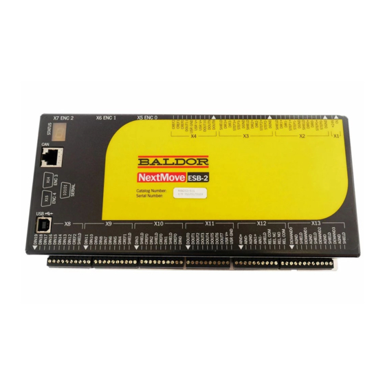
Page 17: Connector Locations
www.baldormotion.com 4.1.1 Connector locations X15 Encoder 4 X14 Encoder 3 DIN19 Serial DIN18 DIN17 DIN16 DIN15 X7 Encoder 2 X8 DIN 12-19 DIN14 DIN13 DIN12 CREF2 Shield DIN11 DIN10 DIN9 X6 Encoder 1 DIN8 DIN7 X9 DIN 4-11 DIN6 DIN5 DIN4 CREF1 Shield... -
Page 18: Analog I/O
4.2 Analog I/O The NextMove ESB-2 provides: Two 12-bit resolution analog inputs. Four 12-bit resolution analog outputs. 4.2.1 Analog inputs The analog inputs are available on connector X12, pins 1 & 2 (AIN0) and 4 & 5 (AIN1). - Page 19 www.baldormotion.com AIN0+ AIN0+ AIN0 AIN0 AIN0- ADC.0 ADC.0 Differential connection Single ended connection Figure 3: AIN0 analog input wiring +24VDC Ù 1.5 k , 0.25 W Ù 1 k , 0.25 W potentiometer AIN0 ADC.0 Figure 4: Typical input circuit to provide 0-10 V (approx.) input from a 24 V source Servo Systems Co.
-
Page 20: Analog Outputs
AIN0- Shield Connect overall shield at one end only Figure 6: Analog output - typical connection to Baldor MicroFlex Servo Systems Co. • 115 Main Road • P.O. Box 97 • Montville, NJ, MN1957 Input / Output 4-5 07045-0097 • (973) 335-1007 • Toll Free: (800) 922-1103... - Page 21 AIN0- Shield Connect overall shield at one end only Figure 7: Analog output - typical connection to Baldor FlexDrive , Flex+Drive , MintDrive Servo Systems Co. • 115 Main Road • P.O. Box 97 • Montville, NJ, 4-6 Input / Output MN1957 07045-0097 •...
-
Page 22: Digital I/O
4.3 Digital I/O The NextMove ESB-2 provides: 20 general purpose digital inputs. 12 general purpose digital outputs. 4.3.1 Digital inputs Digital inputs are available on connectors X8, X9 and X10, as shown in section 4.1.1. The digital inputs are arranged in three groups, each with their own common connection. - Page 23 4.3.1.2 DIN4 - DIN11 Digital inputs DIN4 to DIN11 have a common specification: Opto-isolated digital inputs. Sampling frequency: 1 kHz. Digital inputs DIN4 to DIN11 use CREF1 as their common connection. NextMove ESB-2 100R Mint DIN11 INX.11 TLP280 CREF1...
- Page 24 www.baldormotion.com 4.3.1.4 Auxiliary encoder inputs - DIN17 (STEP), DIN18 (DIR), DIN19 (Z) DIN17-DIN19 may also be used as an auxiliary encoder input. DIN17 accepts step (pulse) signals and DIN18 accepts direction signals, allowing an external source to provide the reference for the speed and direction of an axis. The step frequency (15 kHz maximum) determines the speed, and the direction input determines the direction of motion.
- Page 25 CREF1 User TLP280 supply Figure 14: Digital input - typical connections from a Baldor MicroFlex Servo Systems Co. • 115 Main Road • P.O. Box 97 • Montville, NJ, 4-10 Input / Output MN1957 07045-0097 • (973) 335-1007 • Toll Free: (800) 922-1103...
- Page 26 DIN4 NEC PS2562L-1 CREF1 User TLP280 supply Figure 15: Digital input - typical connections from a Baldor FlexDrive Flex+Drive or MintDrive Servo Systems Co. • 115 Main Road • P.O. Box 97 • Montville, NJ, MN1957 Input / Output 4-11 07045-0097 •...
-
Page 27: Digital Outputs
The maximum allowable power dissipation for the UDN2987 driver is 1.5 W. If this is exceeded the driver may shut down. To reset it, the NextMove ESB-2 must be power cycled. If an output is used to drive an inductive load such as a relay, a suitably rated diode must be fitted across the relay coil, observing the correct polarity. -
Page 28: Other I/O
4.1.1. There are four sets of stepper motor control outputs, operating in the range 0 Hz to 500 kHz. Each of the step (pulse) and direction signals from the NextMove ESB-2 is driven by DS26LS31 line drivers, providing RS422 differential outputs. It is recommended to use separate shielded cables for the step outputs. -
Page 29: Stepper Control Outputs - Models Nsb203
4.1.1. There are four sets of stepper motor control outputs, operating in the range 0 Hz to 500 kHz. Each of the step (pulse) and direction signals from the NextMove ESB-2 is driven by a ULN2803 open collector Darlington output device. The STEPPERDELAY keyword allows a 0 - 4.25 μs delay to be introduced between state changes of the step and direction outputs. -
Page 30: Encoder Inputs 0-4
9 +5 V out Power supply to encoder Five incremental encoders may be connected to NextMove ESB-2, each with complementary A, B and Z channel inputs. Each input channel uses a MAX3095 differential line receiver with pull up resistors and terminators. Encoders must provide RS422 differential signals. - Page 31 www.baldormotion.com 4.4.3.1 Encoder input frequency The maximum encoder input frequency is affected by the length of the encoder cables. The theoretical maximum frequency is 10 million quadrature counts per second. This is equivalent to a maximum frequency for the A and B signals of 2.5 MHz. However, the effect of cable length is shown in Table 1: Maximum cable length A and B signal...
- Page 32 MicroFlex NextMove ESB-2 FlexDrive Flex+Drive MintDrive encoder output CHA+ CHA+ to CPU 120R MAX3095 CHA- CHA- Twisted pair CHB+ CHB+ to CPU 120R MAX3095 CHB- CHB- Twisted pair CHZ+ CHZ+ to CPU 120R MAX3095 CHZ- CHZ- Twisted pair DGND...
-
Page 33: Relay Connections
USB1.1 specification of the NextMove ESB-2. Ideally, the NextMove ESB-2 should be connected directly to a USB port on the host PC. If it is connected to a hub shared by other USB devices, communication could be affected by the activity of the other devices. -
Page 34: Serial Port
NextMove ESB-2 is available with either an RS232 or RS485 serial port (see section 2.2.1). The port is fully ESD protected to IEC 1000-4-2 (15 kV). When the NextMove ESB-2 is connected to Mint WorkBench, the Tools, Options menu item can be used to configure the serial port. -
Page 35: Multidrop Using Rs485 / Rs422
RTS and CTS lines, these must also be connected. Pins 4 and 6 are linked on the NextMove ESB-2. The maximum recommended cable length is 3 m (10 ft) at 57.6 Kbaud (the factory preset rate). When using lower baud rates, longer cable lengths may be used up to maximum of 15 m (49 ft) at 9600 baud. -
Page 36: Connecting Serial Baldor Hmi Operator Panels
4.4.9 Connecting serial Baldor HMI Operator Panels Serial Baldor HMI Operator Panels use a 15-pin male D-type connector (marked PLC PORT), but the NextMove ESB-2 Serial connector uses a 9-pin male D-type connector. The NextMove ESB-2 may be connected as shown in Figure 25:... -
Page 37: Can
NextMove ESB-2 (see section 5.3.2). At the bottom of the Mint WorkBench window, the status bar will show the name of the controller, followed by ‘CANopen’ or ‘Baldor CAN’. If the correct option is not shown, it will be necessary to download alternative firmware by using the Install System File and/or Download Firmware menu items in Mint WorkBench. -
Page 38: Can Wiring
The 0 V connection of all of the nodes on the network must be tied together through the CAN cabling. This ensures that the CAN signal levels transmitted by NextMove ESB-2 or CAN peripheral devices are within the common mode range of the receiver circuitry of other nodes on the network. -
Page 39: Canopen
4.5.3.1 CAN opto-isolators and power supply The NextMove ESB-2 CAN channel is opto-isolated, so a voltage in the range 12-24 V must be applied to pin 5 of the CAN connector. From this supply, an internal voltage regulator provides the 5 V at 100 mA required for the isolated CAN circuit. Connection of the supply can be achieved by modifying an existing cable (see Figure 27). - Page 40 Baldor HMI NextMove ESB-2 NextMove ESB-2 Operator Panel RJ45 RJ45 node CANopen D-type Twisted pairs Twisted pairs CAN+ Power supply CAN- terminal block Figure 27: Typical CANopen network: 24 V applied using modified cable Baldor HMI NextMove ESB-2 NextMove ESB-2...
-
Page 41: Baldor Can
‘1’ (the lower position) for the network to operate correctly. This configures the node's CAN channel to operate on pins 1 and 2 of the RJ45 connectors. On the Baldor CAN node, jumper JP3 can be used to connect an internal 120 Ω terminating resistor, provided the node is at the end of the network. - Page 42 For Baldor CAN the ‘bus’ parameter must be set to 2. Please refer to the Mint help file for further details on Baldor CAN, Mint keywords and keyword parameters. Servo Systems Co. • 115 Main Road • P.O. Box 97 • Montville, NJ,...
-
Page 43: Connection Summary - Minimum System Wiring
4.6 Connection summary - minimum system wiring As a guide, Figure 30 shows an example of the typical minimum wiring required to allow the NextMove ESB-2 and a single axis drive amplifier to work together. Details of the connector pins are shown in Table 2. - Page 44 NextMove ESB-2 Name of Function Connection on amplifier connector signal (Note: connections may be labeled differently) Control supply ground +24 V Control supply +24 V input Encoder0 Encoder0 feedback input Encoder output REL NO Normally open relay contact Enable +24 V...
- Page 45 www.baldormotion.com Servo Systems Co. • 115 Main Road • P.O. Box 97 • Montville, NJ, 4-30 Input / Output MN1957 07045-0097 • (973) 335-1007 • Toll Free: (800) 922-1103 Fax: (973) 335-1661 • www.servosystems.com...
-
Page 46: Operation
5 Operation 5.1 Introduction Before powering the NextMove ESB-2 you will need to connect it to the PC using a serial or USB cable and install the supplied PC software Mint WorkBench. This software includes a number of tools to allow you to configure, tune and program the NextMove ESB-2. If you do not have experience of software installation or Windows applications you may need further assistance for this stage of the installation. -
Page 47: Preliminary Checks
5.1.5.1 Installing the USB driver If you have connected the NextMove ESB-2 to the PC using the USB connection, it will be necessary to install the USB driver. When the NextMove ESB-2 is powered, Windows will automatically detect the controller and request the driver. -
Page 48: Mint Machine Center
The Mint Machine Center (MMC) is used to view the network of connected controllers in a system. Individual controllers and drives are configured using Mint WorkBench. Note: If you have only a single NextMove ESB-2 connected to your PC, then MMC is probably not required. Use Mint WorkBench (see section 5.4) to configure the NextMove ESB-2. -
Page 49: Starting Mmc
In the information pane, click Scan. 3. When the search is complete, click once on ‘NextMove ESB-2' in the controller pane to select it, then double click to open an instance of Mint WorkBench. The NextMove ESB-2 will be already connected to the instance of Mint WorkBench, ready to configure. -
Page 50: Mint Workbench
Mint WorkBench is a fully featured application for programming and controlling the NextMove ESB-2. The main WorkBench window contains a menu system, the Toolbox and other toolbars. Many functions can be accessed from the menu or by clicking a button - use whichever you prefer. -
Page 51: Help File
www.baldormotion.com 5.3.1 Help file Mint WorkBench includes a comprehensive help file that contains information about every Mint keyword, how to use Mint WorkBench and background information on motion control topics. The help file can be displayed at any time by pressing F1. On the left of the help window, the Contents tab shows the tree structure of the help file;... -
Page 52: Starting Mint Workbench
www.baldormotion.com 5.3.2 Starting Mint WorkBench Note: If you have already used MMC to install firmware and start an instance of Mint WorkBench, go straight to section 5.4 to continue configuration. 1. On the Windows Start menu, select Programs, Mint Machine Center, Mint WorkBench. 2. - Page 53 Mint WorkBench has detected new firmware. Click OK to continue.) Click Scan to search for the NextMove ESB-2. When the search is complete, click on NextMove ESB-2 in the list to highlight it, and click Select. Note: If the NextMove ESB-2 is not listed, check the USB or serial lead between the NextMove ESB-2 and the PC.
-
Page 54: Configuring An Axis
5.4 Configuring an axis The NextMove ESB-2 is capable of controlling 4 servo and 4 stepper axes. This section describes how to configure both types of axis. 5.4.1 Selecting the axis type An axis can be configured as either a servo axis or a stepper axis. The factory preset configuration sets all axes as unassigned (off), so it is necessary to configure an axis as either stepper or servo before it can be used. -
Page 55: Selecting A Scale
5. Click Apply. This immediately sets the scaling factor for the selected axis. It will remain in the NextMove ESB-2 until another scale is defined, or power is removed. Servo Systems Co. • 115 Main Road • P.O. Box 97 • Montville, NJ,... -
Page 56: Setting The Drive Enable Output
5.4.3 Setting the drive enable output The drive enable output allows NextMove ESB-2 to disable the drive in the event of an error. Each axis can be configured with its own drive enable output, or can share an output with other axes. -
Page 57: Testing The Drive Enable Output
If this is not working, or the action of the button is reversed, check the electrical connections between the NextMove ESB-2 and drive amplifier. If you are using the relay, check that you are using the correct normally open (REL NO) or normally closed (REL NC) connections. -
Page 58: Stepper Axis - Testing
www.baldormotion.com 5.5 Stepper axis - testing This section describes the method for testing a stepper axis. The stepper control is an open loop system so no tuning is necessary. 5.5.1 Testing the output This section tests the operation and direction of the output. It is recommended that the system is initially tested with the motor shaft disconnected from other machinery. -
Page 59: Servo Axis - Testing And Tuning
www.baldormotion.com 5.6 Servo axis - testing and tuning This section describes the method for testing and tuning a servo axis. The drive amplifier must already have been tuned for basic current or velocity control of the motor. 5.6.1 Testing the demand output This section tests the operation and direction of the demand output for axis 0. - Page 60 www.baldormotion.com 5. To repeat the tests for negative (reverse) demands, type: TORQUE(0)=-5 6. This should cause a demand of -5% of maximum output (-0.5 V) to be produced at the DEMAND0 output. Correspondingly, the Spy window's Velocity display should show a negative value.
-
Page 61: An Introduction To Closed Loop Control
[Demand stopped so you stopped too, but not quite level]. The NextMove ESB-2 tries to correct the error, but because the error is so small the amount of torque demanded might not be enough to overcome friction. - Page 62 www.baldormotion.com The remaining gain terms are Velocity Feed forward (KVELFF) and Acceleration Feed forward (KACCEL) described below. In summary, the following rules can be used as a guide: KPROP: Increasing KPROP will speed up the response and reduce the effect of ...
- Page 63 Figure 34: The NextMove ESB-2 servo loop Servo Systems Co. • 115 Main Road • P.O. Box 97 • Montville, NJ, 5-18 Operation MN1957 07045-0097 • (973) 335-1007 • Toll Free: (800) 922-1103 Fax: (973) 335-1661 • www.servosystems.com...
-
Page 64: Servo Axis - Tuning For Current Control
www.baldormotion.com 5.7 Servo axis - tuning for current control 5.7.1 Selecting servo loop gains All servo loop parameters default to zero, meaning that the demand output will be zero at power up. Most drive amplifiers can be set to current (torque) control mode or velocity control mode;... - Page 65 0.15 seconds. 7. Click Go. The NextMove ESB-2 will perform the move and the motor will turn. As the soon as the move is completed, Mint WorkBench will upload captured data from the NextMove ESB-2. The data will then be displayed in the Capture window as a graph.
-
Page 66: Underdamped Response
www.baldormotion.com 5.7.2 Underdamped response If the graph shows that the response is underdamped (it overshoots the demand, as shown in Figure 35) then the value for KDERIV should be increased to add extra damping to the move. If the overshoot is excessive or oscillation has occurred, it may be necessary to reduce the value of KPROP. -
Page 67: Overdamped Response
www.baldormotion.com 5.7.3 Overdamped response If the graph shows that the response is overdamped (it reaches the demand too slowly, as shown in Figure 36) then the value for KDERIV should be decreased to reduce the damping of the move. If the overdamping is excessive, it may be necessary to increase the value of KPROP. -
Page 68: Critically Damped Response
www.baldormotion.com 5.7.4 Critically damped response If the graph shows that the response reaches the demand quickly and only overshoots the demand by a small amount, this can be considered an ideal response for most systems. See Figure 37. Demand position Measured position Figure 37: Critically damped (ideal) response Servo Systems Co. -
Page 69: Servo Axis - Tuning For Velocity Control
3. Now calculate how many quadrature encoder counts there are per revolution. The NextMove ESB-2 counts both edges of both pulse trains (CHA and CHB) coming from the encoder, so for every encoder line there are 4 ‘quadrature counts’. With a 1000 line... - Page 70 8. Click Go. The NextMove ESB-2 will perform the move and the motor will turn. As the soon as the move is completed, Mint WorkBench will upload captured data from the NextMove ESB-2. The data will then be displayed in the Capture window as a graph.
- Page 71 www.baldormotion.com 9. Using the check boxes below the graph, select the Measured velocity and Demand velocity traces. Measured velocity Demand velocity Figure 38: Correct value of KVELFF It may be necessary to make changes to the calculated value of KVELFF. If the trace for Measured velocity appears above the trace for Demand velocity, reduce the value of KVELFF.
-
Page 72: Adjusting Kprop
0.1. 2. Click Go. The NextMove ESB-2 will perform the move and the motor will turn. As the soon as the move is completed, Mint WorkBench will upload captured data from the NextMove ESB-2. The data will then be displayed in the Capture window as a graph. - Page 73 www.baldormotion.com Demand position Measured position Figure 39: Correct value of KPROP The two traces will probably appear with a small offset from each other, which represents the following error. Adjust KPROP by small amounts until the two traces appear on top of each other (approximately), as shown in Figure 39.
-
Page 74: Servo Axis - Eliminating Steady-State Errors
0.1. 2. Click in the KINTLIMIT box and enter a value of 5. With NextMove ESB-2, the action of KINT and KINTLIMIT can be set to operate in various modes: Never - the KINT term is never applied ... -
Page 75: Digital Input/Output Configuration
www.baldormotion.com 5.10 Digital input/output configuration The Digital I/O window can be used to setup other digital inputs and outputs. 5.10.1 Digital input configuration The Digital Inputs tab allows you to define how each digital input will be triggered, and if it should be assigned to a special purpose function such as a Home or Limit input. - Page 76 4. Now drag the IN1 icon onto the Fwd Limit icon This will setup IN1 as the Forward Limit input of axis 0. 5. Click Apply to send the changes to the NextMove ESB-2. If required, multiple inputs can be configured before clicking Apply.
-
Page 77: Saving Setup Information
5.11 Saving setup information When power is removed from the NextMove ESB-2 all data, including configuration and tuning parameters, is lost. You should therefore save this information in a file, which can be loaded when the unit is next used. - Page 78 A Startup block should be included in every Mint program, so that whenever a program is loaded and run the NextMove ESB-2 will be correctly configured. Remember that every drive/motor combination has a different response. If the same program is used on a different NextMove ESB-2 installation, the Startup block will need to be changed.
- Page 79 www.baldormotion.com Servo Systems Co. • 115 Main Road • P.O. Box 97 • Montville, NJ, 5-34 Operation MN1957 07045-0097 • (973) 335-1007 • Toll Free: (800) 922-1103 Fax: (973) 335-1661 • www.servosystems.com...
-
Page 80: Troubleshooting
If you have followed all the instructions in this manual in sequence, you should have few problems installing the NextMove ESB-2. If you do have a problem, read this section first. In Mint WorkBench, use the Error Log tool to view recent errors and then check the help file. -
Page 81: Nextmove Esb-2 Indicators
Spline. A spline move is being performed. See the SPLINE keyword and related commands. Axis enabled. Torque mode. The NextMove ESB-2 is in Torque mode. See the TORQUE keyword and related commands. Hold to Analog. The axis is in Hold To Analog mode. See the HTA keyword and related commands. -
Page 82: Communication
If the status display shows one of the digits 0 - 7 with a flashing decimal point during startup, this indicates that the NextMove ESB-2 has detected a fault and cannot be started. In this unlikely event, please contact Baldor technical support. -
Page 83: Motor Control
(remove 24 V power and then reconnect). firmware. 6.2.3 Motor control If the problem is not listed below please contact Baldor technical support. Symptom Check Controller appears to be Check that the connections between motor and drive are working but will not cause correct. - Page 84 See sections 5.6.2 to 5.9. a move. Motor is under control, but Verify that the NextMove ESB-2 and drive are correctly when moved to a position and grounded to a common ground point. then back to the start it does...
-
Page 85: Mint Workbench
(remove 24 V power and then reconnect). firmware. Mint WorkBench loses contact Check that the NextMove ESB-2 is powered. with NextMove ESB-2 while Check that a “USB Motion Controller” device is listed in connected using USB Windows Device Manager. If not, there could be a problem with the PC's USB interface. -
Page 86: Canopen
Symptom Check The CANopen bus is ‘passive’ This means that the internal CAN controller in the NextMove ESB-2 is experiencing a number of Tx and/or Rx errors, greater than the passive threshold of 127. Check: 12-24 V is being applied to pin 5 of the RJ45 CAN ... - Page 87 If the node in question does not conform to DS401 or DS403 and is not a Baldor CANopen node, communication is still possible using a set of general purpose Mint keywords. See the Mint help file for further details.
-
Page 88: Baldor Can
12-24 V is being applied to pin 5 of the RJ45 CAN connector, to power the opto-isolators. There is at least one other Baldor CAN node in the network, with jumpers JP1 and JP2 in the ‘1' (lower) position. - Page 89 www.baldormotion.com Servo Systems Co. • 115 Main Road • P.O. Box 97 • Montville, NJ, 6-10 Troubleshooting MN1957 07045-0097 • (973) 335-1007 • Toll Free: (800) 922-1103 Fax: (973) 335-1661 • www.servosystems.com...
-
Page 90: Specifications
Specifications 7 Specifications 7.1 Introduction This section provides technical specifications of the NextMove ESB-2. 7.1.1 Input power Value Description Input power Nominal input voltage 24 VDC (±20%) Power consumption 50 W (2 A @24 V approx.) 7.1.2 Analog inputs Unit... -
Page 91: Digital Inputs
www.baldormotion.com 7.1.4 Digital inputs Unit Value Description Type Opto-isolated USR V+ supply voltage Nominal Minimum Maximum Input voltage Active > 12V Inactive < 2V Input current Maximum per input, USR V+ = 24 V 7.1.5 Digital outputs - general purpose Unit Value Description... -
Page 92: Stepper Control Outputs
www.baldormotion.com 7.1.7 Stepper control outputs Models NSB202... / NSB204... Unit Value Description Output type RS422 (differential) step (pulse) and direction Maximum output frequency Output current Maximum, per output pair Models NSB203... / NSB205... Unit Value Description Output type Open collector step (pulse) and direction Maximum output frequency Output current Maximum sink, per output... - Page 93 7.1.10 CAN interface Unit Value Description Signal 2-wire, isolated Channels Protocols CANopen or Baldor CAN (selected by choice of firmware) Bit rates Kbit/s CANopen 10, 20, 50, 100, 125, 250, 500, 1000 Baldor CAN 10, 20, 50, 125, 250, 500, 1000 7.1.11 Environmental...
- Page 94 EC Declaration of Conformity Date: 14/01/08 Ref: DE00029-000 Manufacturer Baldor UK Ltd. Address Mint Motion Centre, 6 Bristol Distribution Park, Hawkley Drive, Bristol, BS32 0BF, United Kingdom. Hereby declare that the product: NextMove ESB2 Multi-Axis Motion Controller, being one of:...
- Page 95 www.baldormotion.com Servo Systems Co. • 115 Main Road • P.O. Box 97 • Montville, NJ, 7-6 Specifications MN1957 07045-0097 • (973) 335-1007 • Toll Free: (800) 922-1103 Fax: (973) 335-1661 • www.servosystems.com...
-
Page 96: A Accessories
* Available in North and South America only. Table 3: Drive amplifier to NextMove ESB-2 feedback cables If you are not using a Baldor cable, be sure to obtain a cable that is a shielded twisted pair 0.34 mm (22 AWG) wire minimum, with an overall shield. Ideally, the cable should not exceed 30.5 m (100 ft) in length. -
Page 97: Baldor Can Nodes
A.1.2 Baldor CAN nodes Digital I/O can be expanded easily on NextMove ESB-2 using the Baldor CAN (CAN2) connection. This provides a high speed serial bus interface to a range of I/O devices, including: inputNode 8: 8 opto-isolated digital inputs. -
Page 98: Hmi Panels
10" color TFT touch screen with serial interface and Ethernet KPD-TS12C-30E 12.1" color TFT touch screen with serial interface and Ethernet A.1.4 Baldor keypad The Baldor keypad provides an easy to use operator interface for controlling machinery. It has a 4x20 character display and can be connected using either the serial or CANopen interface. -
Page 99: Mint Nc (Cad To Motion Software
www.baldormotion.com A.1.5 Mint NC (CAD to motion software) The Mint NC software provides machine builders with an extremely rapid and flexible solution for creating contouring and profiling machinery and automation. Mint NC provides a PC-based environment that will import information in industry-standard CAD formats including G-code, HPGL and DXF, and generate the required real-time motion commands. -
Page 100: B Mint Keyword Summary
The following table summarizes the Mint keywords supported by the NextMove ESB-2. Note that due to continuous developments of the NextMove ESB-2 and the Mint language, this list is subject to significant change. Check the latest Mint help file for full details of new or changed keywords. - Page 101 www.baldormotion.com Keyword Description To make miscellaneous changes to the auxiliary encoders. AUXENCODERMODE To scale down the auxiliary encoder input. AUXENCODERPRESCALE To set or read the scale factor for the auxiliary encoder input. AUXENCODERSCALE To read the velocity of the auxiliary encoder input. AUXENCODERVEL To set or read the encoder wrap range for the auxiliary encoder AUXENCODERWRAP...
- Page 102 www.baldormotion.com Keyword Description Returns the currently executing cam segment number. CAMINDEX Allows a cam profile to be shifted forwards or backwards over CAMPHASE a fixed number of cam segments. To get the state of the CAMPHASE for a specific axis. CAMPHASESTATUS To change CAM table data.
- Page 103 www.baldormotion.com Keyword Description To write to the position compare registers. COMPAREPOS To set the configuration of an axis for different control types. CONFIG To enable a connection between two remote nodes to be made CONNECT or broken. Returns the status of the connection between this node and CONNECTSTATUS another node.
- Page 104 www.baldormotion.com Keyword Description To get and reset the state of an axis' encoder Z latch. ENCODERZLATCH To set the deceleration rate on the axis for powered stops, in ERRORDECEL the event of an error or stop input. To set or return the digital input to be used as the error input for ERRORINPUT the specified axis.
- Page 105 www.baldormotion.com Keyword Description To control the use of slew speed, acceleration, deceleration FEEDRATEMODE and feedrate override. Overrides the current speed or feedrate being used. FEEDRATEOVERRIDE To set the parameters for the current speed or feedrate being FEEDRATEPARAMETER used. To read the release number of the firmware. FIRMWARERELEASE To create a flying shear by following a master axis with controlled acceleration and deceleration.
- Page 106 www.baldormotion.com Keyword Description To find the phase of the homing sequence currently in HOMEPHASE progress. To read the axis position at the completion of the homing HOMEPOS sequence. To set the speed for the initial seek phase of the homing HOMESPEED sequence.
- Page 107 To set the servo loop acceleration feed forward gain. KACCEL To set the servo loop derivative gain on the servo axes. KDERIV To remap the layout of the keys on a Baldor CAN KEYS KeypadNode. To set the servo loop integral gain.
- Page 108 www.baldormotion.com Keyword Description To set the user digital input configured to be the reverse end of LIMITREVERSEINPUT travel limit switch input for the specified axis. To set the servo loop update interval in microseconds. LOOPTIME To set or read the channel of the input device used for gearing. MASTERCHANNEL To set the distance on the master axis over which the slave will MASTERDISTANCE...
- Page 109 To control the rate of change on a remote analog input before a REMOTEADCDELTA REMOTEADC message is sent. To specify the CAN baud rate of a remote Baldor CAN node REMOTEBAUD (I/O or Keypad). To control the value of a remote analog output channel (DAC).
- Page 110 To read the state of individual digital inputs from a remote CAN REMOTEINX node. To control the update mode for a remote node. REMOTEMODE To specify the node ID of a remote Baldor CAN node (I/O or REMOTENODE Keypad). To access the Object Dictionary of any CANopen node present REMOTEOBJECT on the network.
- Page 111 www.baldormotion.com Keyword Description To perform a reset on all axes. RESETALL To scale axis encoder counts, or steps, into user defined units. SCALEFACTOR To set the baud rate of the RS232 / RS485/422 port. SERIALBAUD To set the forward software limit position on a specified axis. SOFTLIMITFORWARD To set or read the default action taken if a forward or reverse SOFTLIMITMODE...
- Page 112 www.baldormotion.com Keyword Description To set or read the node ID for a CAN node associated with a TERMINALADDRESS terminal. To set or read the device type associated with a given terminal. TERMINALDEVICE To set or read handshaking modes for a terminal. TERMINALMODE To set or read the communication port associated with a given TERMINALPORT...
- Page 113 www.baldormotion.com Servo Systems Co. • 115 Main Road • P.O. Box 97 • Montville, NJ, B-14 Mint Keyword Summary MN1957 07045-0097 • (973) 335-1007 • Toll Free: (800) 922-1103 Fax: (973) 335-1661 • www.servosystems.com...
- Page 114 Abbreviations, 2-4 selecting a scale, 5-10 Accessories, A-1 selecting the axis type, 5-9 Baldor CAN nodes, A-2 setting the drive enable output, 5-11 Feedback cables, A-1, B-1 testing and tuning a servo axis, 5-14 HMI (Human Machine Interface) panels, A-3...
- Page 115 Saving setup information, 5-32 Scale selecting, 5-10 Mint keyword summary, B-1 Serial port, 4-19 Mint Machine Center (MMC), 5-3 connecting serial Baldor HMI panels, 4-21 starting, 5-4 Servo axis, 5-14 Mint NC CAD to Motion software, A-4 adjusting KPROP, 5-27 Mint WorkBench, 5-5...
- Page 116 7-3 Status display, 6-2 Stepper axis control outputs, 4-13, 4-14 Testing servo axis, 5-14 Troubleshooting, 6-1 Baldor CAN, 6-9 CANopen, 6-7 communication, 6-3 help file, 5-6 Mint WorkBench, 6-6 motor control, 6-4 problem diagnosis, 6-1 status display, 6-2...
Need help?
Do you have a question about the NextMove ESB-2 and is the answer not in the manual?
Questions and answers