SMC Networks PSE200 Operation Manual
Multi channel pressure sensor controller
Hide thumbs
Also See for PSE200:
- Operation manual (1 page) ,
- Instruction manual (3 pages) ,
- Manual (23 pages)

Related Manuals for SMC Networks PSE200


Summary of Contents for SMC Networks PSE200
- Page 1 No.PS##-OMH0006-C PRODUCT NAME Multi Channel Pressure Sensor Controller MODEL / Series / Product Number PSE200...
-
Page 2: Table Of Contents
Table of Contents Safety Instructions Model Indication and how to order Summary of Product parts Definition and terminology Mounting and Installation Installation Wiring Internal circuit and wiring example Setting of Function Pressure Setting Setting of Special Function Other Settings Maintenance Troubleshooting Specification Specifications... -
Page 3: Safety Instructions
Safety Instructions These safety instructions are intended to prevent hazardous situations and/or equipment damage. These instructions indicate the level of potential hazard with the labels of "Caution", "Warning" or "Danger". They are all important notes for safety and must be followed in addition to International standards (ISO/IEC) and other safety regulations. - Page 4 Caution The product is provided for use in manufacturing industries. The product herein described is basically provided for peaceful use in manufacturing industries. If considering using the product in other industries, consult SMC beforehand and exchange specifications or a contract if necessary. If anything is unclear, contact your nearest sales branch.
- Page 5 Operator ♦This operation manual is intended for those who have knowledge of machinery using pneumatic equipment, and have sufficient knowledge of assembly, operation and maintenance of such equipment. Only those persons are allowed to perform assembly, operation and maintenance. ♦Read and understand this operation manual carefully before assembling, operating or providing maintenance to the product.
- Page 6 ■NOTE ○Follow the instructions given below when designing, selecting and handling the product. ●The instructions on design and selection (installation, wiring, environment, adjustment, operation, maintenance, etc.) described below must also be followed. ∗Product specifications •Use the specified voltage. Otherwise failure or malfunction can result. •Do not exceed the specified maximum allowable load.
- Page 7 •Do not route wires and cables together with power or high voltage cables. Otherwise the product can malfunction due to interference of noise and surge voltage from power and high voltage cables to the signal line. Route the wires (piping) of the product separately from power or high voltage cables. •Confirm proper insulation of wiring.
- Page 8 •If using the product to detect very small pressure rates, warm up the product for 20 to 30 minutes first. There will be a drift on the display of approximate 1% immediately after the power supply is turned on. •Perform settings suitable for the operating conditions. Incorrect setting can cause operation failure.
-
Page 9: Model Indication And How To Order
Panel mount adapter + Front protective cover ZS-26-C With set screw M3x8 L (2 pcs.) and waterproof seal Front protective cover ZS-26-01 It is an adapter for attaching PSE200 series in the □48 conversion adapter ZS-26-D panel cut size of PSE100 series. No.PS##-OMH0006-C... -
Page 10: Summary Of Product Parts
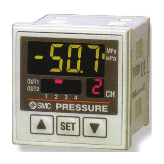
Summary of Product parts ○Names of individual parts Switch output display (Red): Lit when OUT1 (CH1 to CH4) and/or OUT2 (only CH1) is ON. LCD display (Orange): Displays the current status of pressure, setting mode, selected indication unit and error code. button (UP): Selects a mode and increases a set ON/OFF value. -
Page 11: Definition And Terminology
■Definition and terminology Terms Meaning When "8" is shown on the display. It is called 7-segment because 8 consists of 7 7-segment indication pieces of "- (segments)". A function of the Pressure switch to automatically setup pressure just by having equipment hold and release a workpiece via vacuum adsorption. - Page 12 Terms Meaning Fine adjustment mode Refer to "Fine adjustment of indicated value". An indicated pressure value can be adjusted within the range of ±5% R.D. Fine adjustment of indicated (±5% of the indicated value). It is used if a true pressure value is known or to value (function) correct the difference of an indicated value of the measurement equipment nearby that measures the same pressure as the Pressure switch.
- Page 13 Terms Meaning The pressure range in which the Pressure switch satisfies the specifications. Rated pressure range Values over this range can be set if they are within the set pressure range, but cannot assured the specifications to be satisfied. The value currently displayed. For example, when the displayed value is 1.000, ±5%R.D.
-
Page 14: Mounting And Installation
Mounting and Installation ■Installation ○Mounting by panel mount adapter ●Fix the panel mount adapter to the Controller with the set screws M3×8 L (2 pcs.) as attached. •Panel mount adapter (Model: ZS-26-B) Panel mount adapter + Front protective cover (Model: ZS-26-01) □48 conversion adapter (Model: ZS-26-D) ∗: The panel mount adapter can be rotated by 90 degrees for mounting. - Page 15 Notice when removing to the controller ●The Controller with the panel mount adapter can be removed from facility after removing two screws as shown in a figure, by making insert the suitable thin card for the hook of both the sides, pull a panel mount adapter to the front, and remove it. If panel mount adapter is drawn forward with hook caught, the adapter and Controller may be damaged.
-
Page 16: Wiring
■Wiring ○Connection •Connections should only be made with the power supply turned off. •Use separate routes for the Multi Channel Pressure Sensor Controller wiring and any power or high voltage wiring. Otherwise, malfunction may result due to noise. •Ensure that the FG terminal is connected to ground when using a commercially available switch-mode power supply. - Page 17 ○Connector Connecting/Disconnecting •When connecting the connector, insert it straight onto the pin and lock the connector into the square groove in the housing until connector clicks. •When removing the connector, press down the lever with your thumb and pull the connector straight out. Pin No.
-
Page 18: Internal Circuit And Wiring Example
When the lead wire with SMC power and output lead wire (Model: ZS-26-A) is used, the colors of wire (Brown, Blue, White, Gray, Red, Green Yellow) will apply as shown on circuit diagram. PSE200-(M) : NPN open collector 5 outputs + Auto-shift 1 input Max. 30 V, 80 mA... -
Page 19: Setting Of Function
Setting of Function ○Setting procedures Measurement mode Detects pressure, displays values and performs switching. Other functions such as zero clear can also be set if necessary. For connecting at ▼ least 1 sensor other PSE530 series. For connecting only Automatic identification ▼... - Page 20 ○Initial setting Select the setting channel by pressing the button and keep pressing the button for 2 seconds or longer. Initialize can get started. Initial setting is required for each channel. 1, Setting of pressure range •Select the pressure range suitable for the sensor connected. •Press the button and select the pressure range.
- Page 21 •List of output mode •If input pressure fluctuates around the set point when hysteresis is set at 2 digits or less in hysteresis mode, switch output may cause chattering. •Hysteresis is fixed at 3 digits in window comparator mode. When the pressure is set, the space of 7 digits at min.
- Page 22 4, Setting of response time •Set response time of switch output. Output chattering is prevented by setting the response time. •Press the button to select response time. Press the button to set. 5, Selection of pressure setting method •There are two methods for pressure setting: manual and auto-preset, either one of which can be selected.
-
Page 23: Pressure Setting
Pressure Setting ○Manual setting Manually set a set value of the controller. Pressure setting is made for respective channel. 1, Selection of OUT1 [P_1] setting mode •Press the button during the Measurement mode to select channel, and then, press the button to display set values. - Page 24 ○Auto-preset When auto-preset is selected in initialize, the set pressure can be calculated and memorized from measured value. The set value is automatically optimized by repeating the suction and release of the object for the setting. 1, Selection of auto-preset OUT1 •Press the button in Measurement mode to select channel, and then, press the...
-
Page 25: Setting Of Special Function
Setting of Special Function ○Fine adjustment function of displayed value This makes no dispersion on CH1 to CH4 each output value, and make same displayed value. It is possible to do fine adjustment within ±5%R.D. range of the reading data on the displayed value of pressure sensor. - Page 26 ○Auto-shift function This function corrects the setting value of each switch output according to change of pressure source. Even if pressure source is changed, this can do correct decision on switch output. Refer to below or page 26 for detail. •Press the button in the state where [SH1] is displayed, and [CH1] and [on]/[oF] will flicker alternately.
- Page 27 ○Conditions and explanations for auto-shift function •Keep constant pressure for 10 ms or longer from the close signal of auto-shift input. •At auto-shift input, [ooo] is displayed for approximate 1 second. Pressure value at that time is memorized as corrected value [C_5] or [C_3]. •The switch set as auto-shift mode at the time of initial setting operates with the value which applied corrected value [C_5] or [C_3] to setting value.
-
Page 28: Other Settings
Other Settings ○Peak/Bottom hold indication Maximum and minimum values are always detected and updated during measurement. Displayed values can be hold. •Press the button for 2 seconds or longer. •Press the button to select peak/bottom mode, and press the button. •Peak mode: Flickers the maximum pressure value. -
Page 29: Maintenance
Maintenance How to reset the product for power cut or forcible de-energizing The setting of the product is remained as that before power cut or de-energizing. The output condition is also basically recovered to that before power cut or de-energizing, but may change depending on the operating environment. -
Page 30: Troubleshooting
Troubleshooting ○Troubleshooting Applicable pressure switch: PSE200 If a cause applicable to the failure cannot be identified and normal operation can be recovered by replacement with a new Pressure switch, this indicates that the Pressure switch itself was broken. The Pressure switch breakage can be caused by operating environment (network construction, etc.), and so consult with SMC separately to obtain countermeasures. - Page 31 Refer to reference The display fluctuates The display is abnormal No.7 Refer to reference The display disappears No.8 Refer to reference The display breaks off No.8 Refer to reference The display flashes No.9 Pressure indication Refer to reference difference when using No.10 two or more pressure switches...
- Page 32 ○Cross-reference for troubleshooting Reference Problem Possible cause Investigation method Countermeasure •Output remains (1)Check the set pressure. (2)Check the settings of the Indication light operation mode, hysteresis and (1)Reset the pressure setting. Wrong pressure remains on. output style. (2)Reset the setting of setting (Hysteresis mode/window function.
- Page 33 Reference Problem Possible cause Investigation method Countermeasure (1)Check if a current of 80 mA or (1),(2)Connect the load as more is flowing to the output. (2)Check if the connected load specified. satisfies the specifications, and if (3)Use a relay with a surge Over current to the load is shorted.
- Page 34 Reference Problem Possible cause Investigation method Countermeasure Incorrect power Check if the power supply voltage Supply power supply voltage supply is within the range of 12 to 24 VDC. of 12 to 24 VDC. Check the wiring to the power Indicated values supply.
- Page 35 Reference Problem Possible cause Investigation method Countermeasure "M" in the part number means Improper model that the unit cannot be selection changed. Check if there is a "-M" at the end of (Selection of ∗: The unit change function is not the part number printed on the The unit cannot model "without...
- Page 36 ○Error indication function This function is to display error location and content when a problem or an error occurs. Error Name Error Display Error Type Troubleshooting Method OUT1 Turn the power off and remove the Over A load current of switch output is 80 mA current output factor for the over current.
-
Page 37: Specification
Specification ■Specifications Model No. PSE20∗ ∗ 1 Pressure range For positive pressure For vacuum For low pressure For compound Rated pressure range 0 to 1 MPa 0 to -101 kPa 0 to 101 kPa -101 to 101 kPa Set pressure range -0.1 to 1 MPa 10 to -101 kPa -10 to 101 kPa... -
Page 38: Dimensions
■Dimensions ○Body dimensions •Panel mount adapter + Front protective cover •Panel mount adapter + □48 conversion adapter -37- No.PS##-OMH0006-C... - Page 39 Revision history A: Addition of notes related to automatic identification function B: New publication for additional notes. C: Revision Note: Specifications are subject to change without prior notice and any obligation on the part of the manufacturer. © 2009-2010 SMC Corporation All Rights Reserved No.PS##-OMH0006-C...
Need help?
Do you have a question about the PSE200 and is the answer not in the manual?
Questions and answers