SMC Networks PFM5 Series Operation Manual
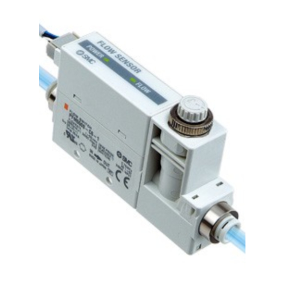
Flow sensor
Hide thumbs
Also See for PFM5 Series:
- Operation manual (1 page) ,
- Installation & maintenance manual (2 pages) ,
- Operation manual (40 pages)
Table of Contents
Advertisement
Quick Links
Advertisement
Table of Contents

Subscribe to Our Youtube Channel
Related Manuals for SMC Networks PFM5 Series


Summary of Contents for SMC Networks PFM5 Series
- Page 1 No.PF##-OMJ0016 Flow sensor PRODUCT NAME PFM5## Series MODEL / Series...
-
Page 2: Table Of Contents
Table of Contents Safety Instructions Model Indication Method Names and Functions of Individual Parts Definition and terminology Mounting and Installation Installation Piping Wiring Troubleshooting Specification Specifications Dimensions Characteristic data No.PF##-OMJ0016... -
Page 3: Safety Instructions
Safety Instructions These safety instructions are intended to prevent hazardous situations and/or equipment damage. These instructions indicate the level of potential hazard with the labels of Caution Warning Danger " " " " " " They are all important notes for safety and must be followed in addition to International standards (ISO/IEC), Japan Industrial Standards (JIS) and other safety regulations *1) ISO 4414: Pneumatic fluid power - - General rules relating to systems. - Page 4 Caution 1. The product is provided for use in manufacturing industries. The product herein described is basically provided for peaceful use in manufacturing industries. If considering using the product in other industries, consult SMC beforehand and exchange specifications or a contract if necessary. If anything is unclear, contact your nearest sales branch.
- Page 5 Operator ♦This operation manual has been written for those who have knowledge of machinery and apparatus that use pneumatic equipment and have full knowledge of assembly, operation and maintenance of such equipment. ♦Please read this operation manual carefully and understand it before assembling, operating or providing maintenance service to the Product.
- Page 6 ■NOTE ○Follow the instructions given below when designing, selecting and handling the product. ●The instructions on design and selection (installation, wiring, environment, adjustment, operation, maintenance, etc.) described below must also be followed. ∗Product specifications •The direct current power supply to combine should be UL approved as follows. Circuit (of class 2) which is of maximum 30Vrms (42.4V peak), with UL 1310 class 2 power supply unit or UL 1585 class 2 transformer.
- Page 7 ●Product handling ∗Installation •Tighten to the specified tightening torque. If the tightening torque is exceeded the mounting screws and brackets may be broken. If the tightening torque is insufficient, the product can be displaced and loosen the mounting screws. (Refer to "Mounting and Installation" on page 14 to 16.) •Do not apply excessive stress to the product when it is mounted with a panel mount.
- Page 8 ∗Wiring •Do not pull the lead wires. In particular, never lift a product equipped with fitting and piping by holding the lead wires. Otherwise damage to the internal parts can result, causing malfunction or to be off the connector. •Avoid repeatedly bending or stretching the lead wire, or placing heavy load on them. Repetitive bending stress or tensile stress can cause the sheath of the wire to peel off, or breakage of the wire.
- Page 9 •Do not expose the product to direct sunlight. If using in a location directly exposed to sunlight, shade the product from the sunlight. Otherwise failure or malfunction can result. •Keep within the specified fluid and ambient temperatures range. The fluid temperature range and ambient temperature range is 0 to 50 Operation under low temperature leads to cause damage or operation failure due to frozen moist in the fluid or air.
-
Page 10: Model Indication Method
Model Indication Method No.PF##-OMJ0016... - Page 11 Option 1 Lead wire connector (2 m) Lead wire connector (2m) Without lead wire connector Connecter cover (Silicone rubber) Option 2 None Bracket Bracket (Without flow adjustment valve) (With flow adjustment valve) Panel Mount Adapter Panel Mount Adapter (Without flow adjustment valve) (With flow adjustment valve) *3: Each option is not assembled with the product, but shipped together.
- Page 12 Part number for options Model No. Option ZS-33-D Lead wire connector ZS-33-F Connecter cover (Silicone rubber) ZS-33-J Panel Mount Adapter (Without flow adjustment valve) ZS-33-JS Panel Mount Adapter (With flow adjustment valve) ZS-33-M Bracket (Without flow adjustment valve) ZS-33-MS Bracket (With flow adjustment valve) ZS-33-R DIN rail mount parts *: See drawing below...
-
Page 13: Names And Functions Of Individual Parts
Names and Functions of Individual Parts Name Description Power source display (green) Turns on when power is supplied. Flashing interval depends on the flow value. Flow display (green) As flow increases, flash interval is shortened. The light turns to red when rated flow is exceeded. Body Product itself. -
Page 14: Definition And Terminology
■Definition and terminology Terminology Definition It reads "full span" or "full scale", and indicates varied analog output F.S. (Full span, Full scale) range at rated value. For example, when analog output is 1 to 5 V, F.S. = 5[V] - 1[V] = 4[V], (ref. 1%F.S. = 4[V]x1% = 0.04[V]) Non-linear output Indicates non linear output. -
Page 15: Mounting And Installation
Mounting and Installation ■Installation Panel mounting •Insert Panel Mount Adapter B (supplied as an accessory) into Section A of Panel Mount Adapter A. Push Panel Mount Adapter B from behind until the display is fixed onto the panel. The pin of Panel Mount Adapter B engages the notched part of Panel Adapter C to fix the display. •The switch can be mounted on a panel with a thickness of 1 to 3.2 mm. - Page 16 Bracket mounting •Fasten the bracket mounting screws to a torque of 0.5±0.05 Nm. Without flow adjustment valve With flow adjustment valve (using ZS-33-M) (using ZS-33-MS) DIN rail mounting •The tightening torque for DIN rail mounting screws and joint screws should be 0.4±0.05 Nm. -15- No.PF##-OMJ0016...
-
Page 17: Piping
■Piping •Ensure tightening torque is correct when installing piping. •Refer to the following table for the appropriate torque values. •Hold the metal part with a spanner when piping. Nominal size of screws Appropriate torque Nm Rc1/8 7 to 9 Rc1/4 12 to 14 •For one-touch fitting, insert the tube to the end so that it is not pulled off. -
Page 18: Wiring
■Wiring Connection •Make connection after turning the power off. •Use a separate route when installing wire. Malfunction stemming from noise may occur if wire is installed in the same route as that of power or high-voltage cable. •Be sure to ground terminal FG when using a switching regulator obtained on the market. If analog output is performed connecting to a switching regulator obtained on the market, switching noise will be superimposed and product specification can no longer be met. - Page 19 Internal circuit and wiring example •OUT1 PFM5□-□-1-□ PFM5□-□-2-□ Analog output 1 to 5 V Analog output 4 to 20 mA Max. Load impedance 600 Ω (24 VDC) Output impedance 1 kΩ Min. load impedance 50 Ω Select response time: No voltage input Reed switch or solid state switch input 30 ms or more Select response speed •To reduce ripple by slowing the response speed when ripple of analog output is large due to the effect of...
-
Page 20: Troubleshooting
Troubleshooting ●Troubleshooting If operation failure happens at a product, please seek a cause of your trouble with the following chart by tracing failure applicable to your case. If the cause you reached seems not to be applicable to your case, and the product operates normally after replacing the failed one with a new one, the product would be broken. - Page 21 Fault Status Possible cause Item to check Countermeasure Check that brown line and Display does not Wiring failure blue line are connected to DC Have correct wiring. light up. (+) and DC (-) respectively. (1) Possibility of foreign matter to be got in. Foreign matter Set up filter or mist separator (2) Possibility of foreign...
- Page 22 Error indication ● This function is to display error location and content when a problem or an error occurs. Error Name Error Display Error Content Troubleshooting Apply flow within rated flow Flow Error Flow exceeds rated flow range. range. Flow display is red. System error.
-
Page 23: Specification
Specification ■Specifications Model PFM510 PFM525 PFM550 PFM511 Dry air, N Ar, CO Measured fluid (Air quality class is JIS B8392-1 1.1.2 to 1.6.2, ISO8573-1 1.1.2 to 1.6.2) Rated flow range* Dry air, N , Ar 0.2 to 10 L/min 0.5 to 25 L/min 1 to 50 L/min 2 to 100 L/min (measurement... - Page 24 Port specification Model φ4 φ8 φ6 φ1/4 (5/32") (5/16") One- One- Port size One- One- touch touch touch touch fitting fitting fitting fitting Straight piping without 95 g 125 g 55 g flow adjustment valve Rear piping without flow 105 g 135 g 65 g adjustment valve...
- Page 25 Cable Specifications: Lead wire with connector (ZS-33-D) Nominal cross section area AWG26 Conductor Outside diameter Approx. 0.50 mm Material Cross-linked vinyl chloride resin compound Insulator Outside diameter Approx 1.00 mm Colours Brown, White, Black, Blue Sheath Material Oil-resistant vinyl chloride resin compound +0.10 φ3.5 Finished outside diameter...
-
Page 26: Dimensions
■Dimensions PFM5**-(N)01/(N)02/F01-1/2 •Connector dimensions -25- No.PF##-OMJ0016... - Page 27 PFM5**-(N)01L/(N)02L/F01L-1/2 -26- No.PF##-OMJ0016...
- Page 28 PFM5*S-(N)01/(N)02/F01-1/2 -27- No.PF##-OMJ0016...
- Page 29 PFM5*S-(N)01L/(N)02L/F01L-1/2 -28- No.PF##-OMJ0016...
- Page 30 PFM5**-F02-1/2 -29- No.PF##-OMJ0016...
- Page 31 PFM5**-F02L-1/2 -30- No.PF##-OMJ0016...
- Page 32 PFM5*S-F02-1/2 -31- No.PF##-OMJ0016...
- Page 33 PFM5*S-F02L-1/2 -32- No.PF##-OMJ0016...
- Page 34 PFM5**-C/N*-1/2 -33- No.PF##-OMJ0016...
- Page 35 PFM5**-C/N*L-1/2 -34- No.PF##-OMJ0016...
- Page 36 PFM5*S-C/N*-1/2 -35- No.PF##-OMJ0016...
- Page 37 PFM5*S-C/N*L-1/2 -36- No.PF##-OMJ0016...
-
Page 38: Characteristic Data
Characteristic data ●Needle revolution - Flow characteristics ●Pressure loss (at 350 [kPa]) -37- No.PF##-OMJ0016... - Page 39 Revision history URL http://www.smcworld.com Note: Specifications are subject to change without prior notice and any obligation on the part of the manufacturer. © 2010 SMC Corporation All Rights Reserved No.PF##-OMJ0016...
Need help?
Do you have a question about the PFM5 Series and is the answer not in the manual?
Questions and answers