Advertisement
Advertisement
Table of Contents

Related Manuals for SMC Networks PSE540 Series


Summary of Contents for SMC Networks PSE540 Series
- Page 1 No.: PS##-OMG0004 Technical Specification Pressure Sensor PSE540 Series...
-
Page 2: Table Of Contents
Contents Safety ……………………………………………………… P2 Model Indication Method ……………………………………………………… P6 Specification ……………………………………………………… P7 Full View with Dimensions ……………………………………………………… P8 Installation ……………………………………………………… P9 Examples of Internal Circuit and Wiring ……………………………………………………… P9 - 1 - PS##-OMG0004... -
Page 3: Safety
Safety ♦ The Pressure Sensor and this technical specification contain essential information for the protection of users and others from possible injury and damage to property and to ensure correct handling. Please check that you fully understand the definition of the following messages (signs) before going on to read the text, and always follow the instructions. - Page 4 ♦ ♦ ♦ ♦ Operator ♦ ♦ ♦ ♦ This technical specification has been written for those who have knowledge of machinery and apparatus that use pneumatic equipment and have full knowledge of assembly, operation and maintenance of such equipment. ♦...
- Page 5 NOTE Follow the instruction given below when designing, selection and handling your pressure sensor. • The instructions on design and selection. Installation, wiring, environment of use, adjustment, operation and maintenance described below must also be followed. • Product specifications ⋅ Operate the pressure sensor with the specified voltage. Operation with a voltage beyond specifications can cause malfunction or damage of the pressure sensor.
- Page 6 ⋅ Keep wiring as short as possible to prevent contamination from noise and induced surge voltage. Do not use a cable longer than 10m. Consult with SMC for the use with a cable longer than 10 m. Connect the 0V DC wire (blue line) directly or as close as possible to the 0V DC terminal of the DC power supply. ⋅...
-
Page 7: Model Indication Method
Model Indication Method PSE54 Option No symbol None Connector for PSE200 1pc Connector for PSE300 1pc Pipe Specification M3 × 0.5 M5 × 0.8 R1/8 (with M5 female screw) NPT1/8 (with M5 female screw) φ4 reducer φ 6 reducer M5 female screw, through type IM5H M5 female screw, through type with settinghole... -
Page 8: Specification
Specification Model PSE541 PSE543 Rated Pressure Range 0 to -101kPa -100 to 100kPa Withstand Pressure 500kPa Fluid Air, Non-corrosive gases, Incombustible gases 12 to 24VDC, ripple ( p-p ) ±10% or less ( Protected against inverse connection ) Power Supply Voltage Current Consumption 15mA or less Analog Output... -
Page 9: Full View With Dimensions
Full View with Dimensions PSE54 (A) - PSE54 PSE54 10.8 11.5 M3: M3 0.5 Width across flat 7 M5: M5 0.8 3000 PSE54 (A) - 01: R1/8 N01: NPT1/8 M5 0.8 PSE54 (A) - PSE54 -R04 PSE54 -R06 PSE54 (A) - IM5 M5 0.8 PSE54 (A) - IM5H... -
Page 10: Installation
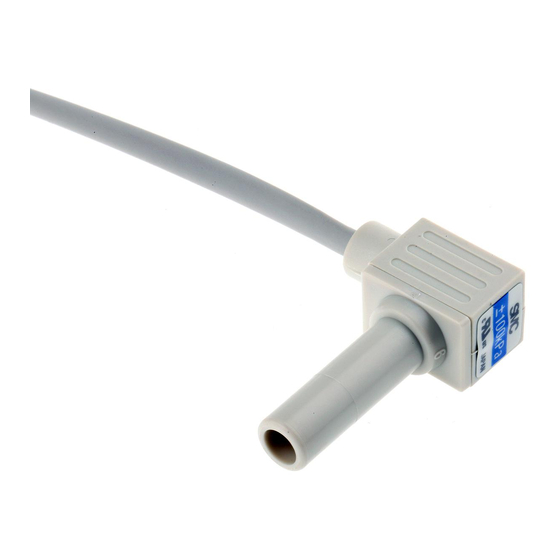
Installation Attaching the connector to the lead wire ⋅ Sensor wire is stripped as shown in the right figure. ⋅ The core of the corresponding color shown in the following table is put into the pin of the number stamped on the connector for sensor connection to the back. Color of cable core Pin No.
Need help?
Do you have a question about the PSE540 Series and is the answer not in the manual?
Questions and answers