SMC Networks PSE570 Operation Manual
Pressure sensor for general fluids
Hide thumbs
Also See for PSE570:
- Operation manual (51 pages) ,
- Manual (16 pages) ,
- Quick start manual (11 pages)

Subscribe to Our Youtube Channel
Related Manuals for SMC Networks PSE570


Summary of Contents for SMC Networks PSE570
- Page 1 No.PS※※-OMS0005-E PRODUCT NAME Pressure Sensor for General Fluids MODEL / Series / Product Number PSE570/573/574...
-
Page 2: Table Of Contents
Table of Contents Safety Instructions Model Identification and How to Order Names of Parts of Product and Handling Precautions Mounting and Installation Wiring Troubleshooting Specification Specifications Dimensions No.PS※※-OMS0005-E... -
Page 3: Safety Instructions
Safety Instructions These safety instructions are intended to prevent hazardous situations and/or equipment damage. These instructions indicate the level of potential hazard with the labels of "Caution", "Warning" or "Danger". They are all important notes for safety and must be followed in addition to International Standards (ISO/IEC) , and other safety regulations. - Page 4 Safety Instructions Caution 1.The product is provided for use in manufacturing industries. The product herein described is basically provided for peaceful use in manufacturing industries. If considering using the product in other industries, consult SMC beforehand and exchange specifications or a contract if necessary. If anything is unclear, contact your nearest sales branch.
- Page 5 Operator This operation manual is intended for those who have knowledge of machinery using pneumatic equipment, and have sufficient knowledge of assembly, operation and maintenance of such equipment. Only those persons are allowed to perform assembly, operation and maintenance. Read and understand this operation manual carefully before assembling, operating or providing maintenance to the product.
- Page 6 Caution ■After maintenance is complete, perform appropriate functional inspections and leak tests. Stop operation if the equipment does not function properly or there is a leakage of fluid. When leakage occurs from parts other than the piping, the product might be faulty. Disconnect the power supply and stop the fluid supply.
- Page 7 ●Product handling Installation Follow the specified tightening torque. Excessive tightening torque can break the Pressure Sensor. Insufficient tightening torque can displace the Pressure Sensor from the original position or loosen the mounting screws. Refer to the following table for the appropriate torque values. Nominal size screws Appropriate tightening torque (Nm) R1/8...
- Page 8 Environment Do not use the product in area that is exposed to corrosive gases, chemicals, sea water, water or steam. Otherwise failure or malfunction can result. Do not use in a place where the product could be splashed by oil or chemicals. If the product is to be used in an environment containing oils or chemicals such as coolant or cleaning solvent, even for a short time, it may be adversely affected (damage, malfunction, or hardening of the lead wires).
-
Page 9: Model Identification And How To Order
Model Indication and How to Order ○Option Description Part No. Remarks Lead wire and M12 connector (3 m) Straight ZS-37-A 1 pc. Lead wire and M12 connector (3 m) Right angle ZS-37-B 1 pc. Connector for pressure sensor controller ZS-28-CA-4 1 pc. -
Page 10: Names Of Parts Of Product And Handling Precautions
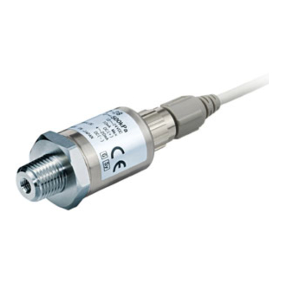
Names of Parts of Product and Handling Precautions ○Names of parts of product •Only fluids which are non-corrosive to C3604 + electroless nickel plated, AI203 (aluminum oxide) and FKM should be used. ○Handling precautions •When piping, apply a spanner to the piping section of the sensor. Nominal size screws Appropriate tightening torque (Nm) R1/8... -
Page 11: Mounting And Installation
Mounting and Installation ■Wiring ○Connector pin numbers When the lead wire and connector (ZS-37-A or ZS-37-B) designated for the PSE570 is used, the wire colours will apply as shown in the diagram. Connector pin numbers (on the lead wire) •ZS-37-A •ZS-37-B... - Page 12 Refer to the following table for pressure sensor compatibility with pressure sensor controllers. Refer to the Operation Manual of each pressure sensor controller for handling them. Pressure sensor controller No. PSE20 series PSE30 series PSE31 series PSE570-□ PSE570-□-28 PSE570-□ Pressure sensor No. PSE573-□ PSE573-□-28 PSE573-□...
- Page 13 ○Attaching the connector to the lead wire Sensor wire is stripped as shown in the right figure. Do not cut the insulation. The core of the corresponding colour shown in the following table is put into the pin of the number stamped on the connector for sensor connection to the back.
- Page 14 ○Internal circuit and wiring example Output specification □-□ PSE57 Voltage output: 1 to 5 V Output impedance: Approx. 1 kΩ □-□ PSE57 Current output: 4 to 20 mA Allowable load impedance: 500 Ω or less (at 24 VDC) 100 Ω or less (at 12 VDC) : The unconnected terminals are used in SMC, so please do not connect them.
-
Page 15: Troubleshooting
Troubleshooting ○Cross-reference for troubleshooting Problem Possible cause Investigation method Countermeasure Check if the analogue output line is Incorrect wiring Correct the wiring. connected with a load. Non-compliance (1) Check if the proper load is connected. with the load (2) Check if input impedance of input Connect a proper load. -
Page 16: Specification
Specification ■Specifications Model No. PSE570 PSE573 PSE574 Rated pressure range 0 to 1 MPa -100 to 100 kPa 0 to 500 kPa Pressure spec. Withstand pressure 3.0 MPa 600 kPa 1.5 MPa Temperature characteristics ±2%F.S. (0 to 50 ±3%F.S. (0 to 50 (Based on 25 ±3%F.S. - Page 17 ○Analogue output Range Rated pressure range For positive pressure 0 to 1 MPa 1 MPa Compound pressure -100 to 100 kPa -100 kPa 100 kPa For positive pressure 0 to 500 kPa 500 kPa -16- No.PS※※-OMS0005-E...
-
Page 18: Dimensions
■Dimensions Model No. PSE57□-01 R1/8 PSE57□-02 R1/4 Lead wire and connector ZS-37-A ZS-37-B -17- No.PS※※-OMS0005-E... - Page 19 Adapter with throttle ZS-31-X□□□ Model No. ZS-31-X188 R1/8 Rc1/8 ZS-31-X175 R1/4 Rc1/4 -18- No.PS※※-OMS0005-E...
- Page 20 Revision history A: Contents are added. B: Contents are added. C: Contents revised in several places. D: Contents revised in several places. E: Contents revised in several places. [July 2018] 4-14-1, Sotokanda, Chiyoda-ku, Tokyo 101-0021 JAPAN Tel: + 81 3 5207 8249 Fax: +81 3 5298 5362 http://www.smcworld.com Note: Specifications are subject to change without prior notice and any obligation on the part of the manufacturer.
Need help?
Do you have a question about the PSE570 and is the answer not in the manual?
Questions and answers