SMC Networks PSE200 Instruction Manual
Multi channel pressure sensor controller
Hide thumbs
Also See for PSE200:
- Operation manual (39 pages) ,
- Installation & maintenance manual (32 pages) ,
- Manual (23 pages)
Table of Contents
Advertisement
Quick Links
PSE200-TF2Z048EN
ORIGINAL INSTRUCTIONS
Instruction Manual
Multi Channel Pressure Sensor Controller
PSE200 / PSE201
The intended use of the multi channel pressure sensor controller is to
monitor and display information from up to four pressure sensors.
1 Safety Instructions
These safety instructions are intended to prevent hazardous situations
and/or equipment damage. These instructions indicate the level of
potential hazard with the labels of "Caution," "Warning" or "Danger."
They are all important notes for safety and must be followed in addition
to International Standards (ISO/IEC)
*1)
, and other safety regulations.
*1)
ISO 4414: Pneumatic fluid power - General rules relating to systems.
ISO 4413: Hydraulic fluid power - General rules relating to systems.
IEC 60204-1: Safety of machinery - Electrical equipment of machines.
(Part 1: General requirements)
ISO 10218-1: Manipulating industrial robots -Safety. etc.
• Refer to product catalogue, Operation Manual and Handling
Precautions for SMC Products for additional information.
• Keep this manual in a safe place for future reference.
Caution indicates a hazard with a low level of risk which, if
Caution
not avoided, could result in minor or moderate injury.
Warning indicates a hazard with a medium level of risk
Warning
which, if not avoided, could result in death or serious injury.
Danger indicates a hazard with a high level of risk which, if
Danger
not avoided, will result in death or serious injury.
Warning
• Always ensure compliance with relevant safety laws and
standards.
• All work must be carried out in a safe manner by a qualified person in
compliance with applicable national regulations.
• This product is class A equipment intended for use in an industrial
environment. There may be potential difficulties in ensuring
electromagnetic compatibility in other environments due to conducted
or radiated disturbances.
• Refer
to
the
operation
manual
on
the
SMC
(URL: https://www.smcworld.com) for more safety instructions.
Warning
Special products (-X) might have specifications different from those
shown in the specifications section. Contact SMC for specific drawings.
2 Specifications
2.1 General specifications
Model No.
PSE20#
For positive
For
Pressure range
pressure
vacuum
Rated pressure
0 to -101
0 to 1 MPa
range
kPa
-0.1 to 1
10 to -101
Set pressure range
MPa
kPa
Setting/Display
0.1 kPa
0.1 kPa
resolution
Power supply
12 to 24 VDC, ripple (p−p) 10% or less
voltage
(Protected against inverse connection)
Current
55 mA or less (except for current for sensor)
consumption
Power supply
[Power supply voltage] -1.5 V
voltage for sensor
Power supply
Max. 40 mA or less (Max. total consumed current
current for sensor
is 100 mA for 4 sensors)
1 to 5 VDC (Input impedance: approx. 800 kΩ)
Input signal
Number of input
4 inputs
With over voltage protection
Input protection
(applicable to voltage up to 26.4 V)
Automatic
Provided
identification
Hysteresis mode: Variable
Hysteresis
Window comparator mode: Fixed 3 digits
Output type
NPN or PNP open collector output
Number of
5 outputs (2 outputs for sensor input CH1, and 1
outputs
output each for CH2 to CH4)
Max. load
80 mA
current
Max. applied
30 VDC (At NPN output)
voltage
Residual
1 V or less (At 80 mA load current)
voltage
Output
With short circuit protection
protection
Response time
5 ms or less
Anti-chattering
20, 160, 640 ms selectable
function
Repeatability
±0.1%F.S. ±1 digit
Indicator accuracy
(Ambient temp. 25
±0.5%F.S. ±1 digit
o
C)
Display for measured value: 4 digits, 7-segment
Display method
(Orange)
Display for channel: 1 digit, 7-segment (Red)
Indicator
Light when ON (Red)
Non-voltage input (Reed or solid state), Input 10
Auto-shift input
ms or less,
Setting ON/OFF is possible independently
Enclosure
Front part: IP65 (panel mounting), Others: IP40
Ambient temp.
Operation: 0 to 50
range
(no condensation or freezing)
Ambient
Operation, Storage: 35 to 85% RH
website
humidity range
(no condensation)
Withstand
1000 VAC, 1 min. between lead block and case
voltage
50 MΩ or more (at 500 VDC)
Insulation
resistance
between lead block and case
Temp.
±0.5% F.S. (at 25
characteristics
Power supply and output connection: 8P
Connection
connector, Sensor connection: e-con
Oil resistance vinyl cabtyre cable,
Power
8 cores φ4.8 2 m
supply/Output
Sectional area of conductor: 0.15 mm
connection cable
Outside diameter of insulator: 0.9 mm
Body: PBT, Display: Transparent nylon,
Material
Rubber cover for the rear: CR
55 g (not including lead wire)
2 Specifications (continued)
Weight
113 g (including lead wire)
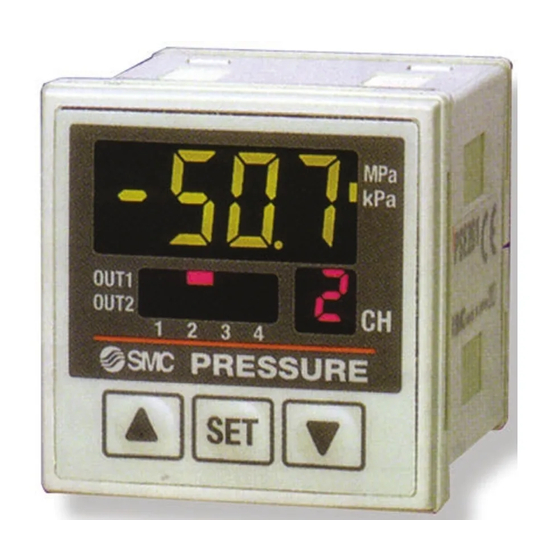
3 Names and function of parts
For low
For
pressure
compound
0 to 101
-101 to
kPa
101 kPa
-10 to 101
-101 to
kPa
101 kPa
0.1 kPa
0.001 MPa
Switch output display (Red): ON when OUT1 (CH1 to CH4) and/or
LCD display (Orange): Displays the current status of pressure, setting
button (UP):
button (DOWN):
button (SET):
Unit display (Orange): Lit ON the indicator of selected unit. For the
Unit label:
Channel display (Red): Indicate the CH1 to CH4 that is selected at that
4 Installation
4.1 Installation
• Do not install the product unless the safety instructions have been read
and understood.
4.2 Environment
• Do not use in an environment where corrosive gases, oil, chemicals,
salt water or steam are present.
• Do not use in an explosive atmosphere.
• Do not expose to direct sunlight. Use a suitable protective cover.
• Do not install in a location subject to vibration or impact in excess of
the product's specifications.
• Do not mount in a location exposed to radiant heat that would result in
temperatures in excess of the product's specifications.
4.3 Mounting with Panel mount adapter
• Fix the panel mount adapter to the controller using the set screws M3
x 8L (2 pcs.) supplied.
Panel mount adapter (Model: ZS-26-B)
o
C, Storage: -10 to 60
o
C
Panel mount adapter + Front protective cover (Model: ZS-26-01)
□48 conversion adapter (Model: ZS-26-D)
o
C reference)
2
• Panel mounting of the controller conforms to IP65 rating, if the panel
mount adapter is installed correctly and the sensor monitor is seated
correctly (if the □48 conversion adapter is used then IP40). Tighten the
screws by 1/4 to 1/2 turn more after the head makes contact with the
panel.
4 Installation (continued)
4.4 Panel cut-out dimensions
OUT2 (only CH1) is ON.
Note: When removing the Controller
• The controller with panel mount adapter can be removed from the
mode, selected indication unit and error code.
installation after removing two screws, by using a thin card to release
Selects a mode and increases the set ON/OFF
the hook on both sides, pull the panel mount adapter forward and
value.
remove it. If the panel mount adapter is drawn forward with the hook
caught, the adapter and controller may be damaged.
Selects a mode and decreases the set ON/OFF
value.
Changes the mode and sets a set value.
Controller without unit selection function, the
unit is fixed to SI (MPa or kPa).
Attach the unit label (kgf/cm
2
, bar, psi, inHg,
mmHg) with the unit selection function.
time.
5.1 Wiring Connection
• Connections should be made with the power supply turned OFF.
• Do not insert or remove the sensor connector with the power ON.
Warning
• Use a separate route for the product wiring and any power or high
voltage wiring. Otherwise, malfunction may result due to noise.
• Ensure that the FG terminal is connected to ground when using a
commercially available switch-mode power supply.
Warning
Connector Connecting / Disconnecting
• When connecting the connector, insert it straight onto the pins and lock
the connector into the groove in the housing until the connector clicks.
• When removing the connector, press down the lever to disengage the
lever and pull the connector straight out.
5.2 Power connector pin layout
Panel thickness:
0.5 to 8.0 mm
Page 1 of 3
Advertisement
Table of Contents

Related Manuals for SMC Networks PSE200


Summary of Contents for SMC Networks PSE200
- Page 1 Multi Channel Pressure Sensor Controller Rated pressure 0 to -101 0 to 101 -101 to 0 to 1 MPa range 101 kPa PSE200 / PSE201 -0.1 to 1 10 to -101 -10 to 101 -101 to Set pressure range 101 kPa Setting/Display 0.1 kPa...
- Page 2 • Not following proper maintenance procedures could cause the product For each button press, channel selection can be carried out, like PSE200-(M)#: NPN open collector 5 outputs + Auto-shift 1 input to malfunction and lead to equipment damage. [1→2→3→4→1→…]. The display shows the pressure value, which is Max.
- Page 3 PSE200-TF2Z048EN 14 Limitations of Use 14.1 Limited warranty and Disclaimer/Compliance Requirements Refer to Handling Precautions for SMC Products. 15 Product Disposal This product shall not be disposed of as municipal waste. Check your local regulations and guidelines to dispose of this product correctly, in order to reduce the impact on human health and the environment.
Need help?
Do you have a question about the PSE200 and is the answer not in the manual?
Questions and answers