Advertisement
Quick Links
Multi-channel Controller
Series
Input/Output specifications
0
1
Accessory: Power supply/Output connection cable (2 m)
Included with the controller.
Option
When only optional parts are required, order with the part numbers listed below.
Description
Panel mount adapter
Front protective cover
Front protective cover +
Panel mount adapter
48 conversion adapter
This adapter is used to
mount Series PSE200 on
the panel fitting of Series
PS100.
Connector
16-3-6
SHOP ONLINE at www.airlinehyd.com
PSE200
PSE20 0
NPN 5 outputs + Auto shift input
PNP 5 outputs + Auto shift input
Unit specifications
With unit display switching function
Nil
M
Note)
Fixed SI unit
Note) Fixed unit
For vacuum low pressure & compound
pressure: kPa
For high pressure: MPa
Power supply/Output connection cable
ZS-26-A
Part no.
Waterproof seal, screws included
ZS-26-B
ZS-26-01
ZS-26-C
Waterproof seal, screws included
ZS-26-D
48 conversion adapter
Order panel mount adapter separately.
ZS-26-E (4 pcs. per set)
How to Order
M
Option 2
Nil
Sensor connector (4 pcs.)
4C
Option 1
Nil
Panel mount
A
Waterproof seal
(Accessory)
Front protective cover + Panel mount
B
Front protective cover
Waterproof seal
(Accessory)
Note
Without connector
Connector
Without panel mount/protective cover
Mounting screws (M3 x 8L)
Panel mount adapter
Panel
Mounting screws (M3 x 8L)
Panel mount adapter
Panel
(Accessory)
(Accessory)
800-999-7378
Advertisement

Related Manuals for SMC Networks PSE200-M Series


Summary of Contents for SMC Networks PSE200-M Series
- Page 1 Multi-channel Controller PSE200 Series How to Order PSE20 0 Option 2 Input/Output specifications Without connector Sensor connector (4 pcs.) NPN 5 outputs + Auto shift input PNP 5 outputs + Auto shift input Unit specifications With unit display switching function Note) Fixed SI unit Connector...
- Page 2 PSE200 Series Multi-channel Controller Specifications Model PSE200 PSE201 Output specification NPN open collector PNP open collector Power supply voltage 12 to 24 VDC ±10%, Ripple (p-p) 10% or less (With power supply polarity protection) 55 mA or less (Current consumption for sensor is not included.) Current consumption [Power supply voltage] –1.5 V Power supply voltage for sensor...
- Page 3 PSE200 Series Dimensions PSE200 & PSE201 40.1 18.7 Connector (option) OUT1 PSE200 OUT2 PRESSURE MADE IN JAPAN Sensor connector (4P x 4) Connector (Option) PIN no. Terminal DC (+) IN (1 to 5 V) DC (–) N.C. Power supply/Output connector (8P) Power supply/Output connection cable (Included) Pin no.
- Page 4 PSE200 Series Multi-channel Controller Dimensions Front protective cover + Panel mount 42.4 ZSE„ ISE„ OUT1 OUT2 PRESSURE Panel mount adapter Front protective cover Waterproof seal Panel 48 conversion adapter + Panel mount ISA2 IS„ PF2„ IF„ OUT1 OUT2 Data PRESSURE Panel mount adapter Waterproof seal Panel...
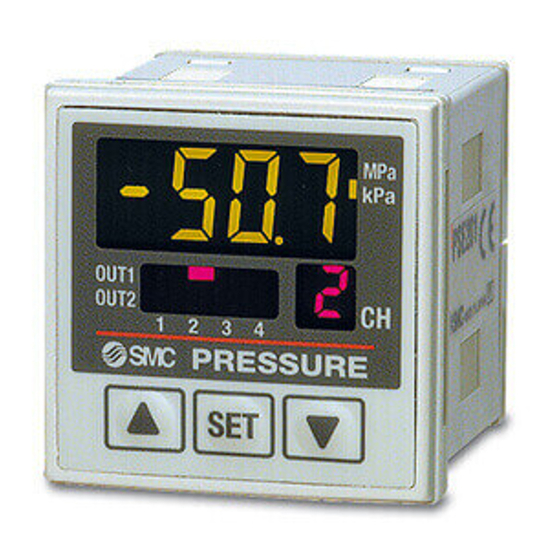
- Page 5 PSE530/200 Series Descriptions 4-digit display Unit display Displays measured The selected unit lights up. Use pressure value, content for unit labels for units other than each setting, and error code. MPa and kPa. Switch output display Unit labels Displays the output status of OUT1 (CH1 to CH4), OUT2 kgf/cm bar PSI inHg mmHg...
- Page 6 PSE530/200 Series Multi-channel Controller/Pressure Sensor Operation 1: Initial Setting Channel selection OUT1 OUT2 PRESSURE ZSE„ ISE„ Press button and hold for 2 seconds or longer. Range setting OUT1 OUT2 PRESSURE Compound pressure Vacuum Low pressure High pressure ISA2 IS„ Note) Sensor range varies depending on the type of pressure sensor. Pressure Sensor/Sensor Range Sensor supply pressure (Compound pressure)
- Page 7 PSE530/200 Series Operation 1: Initial Setting Response time setting OUT1 OUT2 PRESSURE 5 ms 20 ms 160 ms 640 ms Press button. Anti-chattering function Pressure ↑ Momentary change Devices such as large bore cylinders and high-flow vacuum ejectors consume a large volume of air when they operate, and this may cause a momentary drop in the supply pressure.
- Page 8 PSE530/200 Series Multi-channel Controller/Pressure Sensor Operation 2: Pressure Setting Manual setting Channel selection Output mode Hysteresis mode: Hysteresis of the switch output can be set arbitrarily. <Normally open> OUT1 Hysteresis OUT2 PRESSURE Switch output 1 & 2 ZSE„ ISE„ High pressure: Compound pressure type Positive pressure type High vacuum: Vacuum type <Normally closed>...
- Page 9 PSE530/200 Series Operation 2: Pressure Setting Auto preset Channel selection OUT1 OUT2 PRESSURE Adsorption Verification High Suction Vacuum Auto preset mode Work 1 Work 2 Work n OUT1 auto preset preparation Max. A Prepare the equipment to be set in this mode.
- Page 10 PSE530/200 Series Multi-channel Controller/Pressure Sensor Operation 3: Special Setting Precision indicator setting Refer to Display calibration function on page 16-3-17 for details. Calibration mode Press and hold for 2 seconds or longer. OUT1 OUT2 PRESSURE ZSE„ ISE„ Channel selection Calibration mode After setting all 4 channels, press button.
- Page 11 PSE530/200 Series Operation 3: Special Setting Auto shift Refer to Auto shift function on page 16-3-17 for details. Auto shift mode Displays alternately OUT1 OUT1 OUT2 OUT2 PRESSURE PRESSURE Displays alternately OUT1 OUT2 PRESSURE Displays alternately OUT1 OUT2 PRESSURE Displays alternately OUT1 OUT2...
- Page 12 PSE530/200 Series Multi-channel Controller/Pressure Sensor Function Details Display calibration function Copy function This function eliminates slight differences in the output values of all 4 Information that can be copied includes the following: q Pressure set channels and allows uniformity in the numbers displayed. Displayed values, w Range settings, e Display Units, r Output modes, t values of the pressure sensors can be adjusted to within ±5%.
- Page 13 PSE530/200 Series Operation 4: Other Functions Reset Press and hold for 1 second or longer. Key lock Lock/Unlock selection Press and hold for 4 seconds or longer. Lock Unlock To measuring mode Note) Channel selection and channel scan operation will not be locked even if the key lock function is on. Peak/Bottom display Peak/Bottom selection Press and hold for...
- Page 14 Series Specific Product Precautions 1 Be sure to read before handling. { Pressure Sensor { Controller Handling Handling Warning Warning 1. Do not drop, bump, or apply excessive impacts 1. Do not drop, bump, or apply excessive impacts (980 ZSE„ (1000 m/s ) while handling.
- Page 15 Series Specific Product Precautions 2 Be sure to read before handling. Mounting Wiring Caution Caution 1. Connecting sensor cable and connector (ZS-26-E) The front face of the panel mount conforms to IP65 (IP40 when using the 48 conversion adapter); • Cut the sensor cable as shown below. however, there is a possibility of liquid filtration if the •...
- Page 16 Series Specific Product Precautions 3 Be sure to read before handling. Wiring Caution 3. Connecting to other series ZSE„ • Any pressure sensor (SW) can be connected as long as it ISE„ generates analog output (1 to 5 V) signal. However, the pressure range must match.
- Page 17 Safety Instructions These safety instructions are intended to prevent a hazardous situation and/or equipment damage. These instructions indicate the level of potential hazard by labels of "Caution", "Warning" or "Danger". To ensure safety, be sure to observe ISO 4414 Note 1) Note 2) JIS B 8370 and other safety practices.
- Page 18 Common Precautions Be sure to read before handling. For detailed precautions on every series, refer to main text. 4. Use clean air Selection If the compressed air supply is contaminated with chemicals, Warning cynthetic materials, corrosive gas, etc., it may lead to break down or malfunction.
- Page 19 Quality Assurance Information (ISO 9001, ISO 14001) Reliable quality of products in the global market SMC’s quality control system To enable our customers throughout the world to use our products with even greater confidence, SMC has Make customers our first priority, offering them reliable and Create new obtained certification for international...
- Page 20 SMC Product Conforming to Inter SMC products complying with EN/ISO, CSA/UL standards are supporting CE Mark The CE mark indicates that machines and components meet essential requirements of all the EC Directives applied. It has been obligatory to apply CE marks indicating conformity with EC Directives when machines and components are exported to the member Nations of the EU.
- Page 21 SMC Product Conforming to International Standards national Standards you to comply with EC directives and CSA/UL standards. Mark of compliance Mark of compliance for CSA/UL for CSA í CSA Standards & UL Standards UL and CSA standards have been applied in North America (U.S.A. and Canada) symbolizing safety of electric products, and are defined to mainly prevent danger from electric shock or fire, resulting from trouble with electric products.
- Page 22 SMC’s Global Service Network America Europe U.K. SMC Pneumatics (U.K.) Ltd. U.S.A. SMC Corporation of America Vincent Avenue, Crownhill, Milton Keynes, MK8 0AN, Backinghamshire, U.K. 3011 North Franklin Road Indianapolis, IN 46226, U.S.A. TEL: 01908-563888 FAX: 01908-561185 TEL: 317-899-4440 FAX: 317-899-3102 GERMANY SMC Pneumatik GmbH CANADA...
- Page 23 SMC’s Global Service Network Europe Oceania/Asia FINLAND SMC Pneumatics Finland OY AUSTRALIA SMC Pneumatics (Australia) Pty.Ltd. 14-18 Hudson Avenue Castle Hill NSW 2154, Australia PL72, Tiistinniityntie 4, SF-02231 ESP00, Finland TEL: 02-9354-8222 FAX: 02-9894-5719 TEL: 09-8595-80 FAX: 09-8595-8595 NORWAY SMC Pneumatics Norway A/S NEW ZEALAND SMC Pneumatics (New Zealand) Ltd.
Need help?
Do you have a question about the PSE200-M Series and is the answer not in the manual?
Questions and answers