SMC Networks PSE550 Technical Specifications
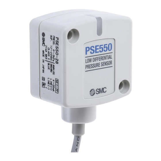
Pressure sensor
Hide thumbs
Also See for PSE550:
- Operation manual (16 pages) ,
- Manual (16 pages) ,
- Instruction manual (2 pages)

Related Manuals for SMC Networks PSE550


Summary of Contents for SMC Networks PSE550
- Page 1 No.: PS##-OMG0009 Technical Specifications Product name : Pressure sensor Model : PSE550...
-
Page 2: Table Of Contents
Contents Safety …………………………………………………P2 …………………………………………………P6 Model Indication Method Specification …………………………………………………P7 Dimension …………………………………………………P8 Installation …………………………………………………P9 Examples of Internal Circuit and Wiring …………………………………………………P10 - 1 - PS##-OMG0009... -
Page 3: Safety
Safety The Pressure Sensor and this technical specification contain essential information for the protection of users and others from possible injury and damage to property and to ensure correct handling. Please check that you fully understand the definition of the following messages (signs) before going on to read the text, and always follow the instructions. - Page 4 Operator ♦This technical specification has been written for those who have knowledge of machinery and apparatus that use pneumatic equipment and have full knowledge of assembly, operation and maintenance of such equipment. ♦Please read this technical specification carefully and understand it before assembling, operating or providing maintenance to the pressure sensor.
- Page 5 NOTE Follow the instruction given below when designing, selection and handling your pressure sensor. ♦ ♦ ♦ ♦ The instructions on design and selection Installation, wiring, environment of use, adjustment, operation and maintenance described below must also be followed. ∗ ∗ ∗ ∗ Product specifications •...
- Page 6 • The direct-current power supply to combine should use UL authorization power supply which is the class 2 power supply based on UL 1310 or the power supply is using the transformer of a class 2 based on UL 1585. ∗...
-
Page 7: Model Indication Method
Please order by the following model number connected with PSE300. when the option is necessary. Option Model number Contens Bracket ZS-30-A Connector for PSE300 ZS-28-C Analog output PSE550 PSE550-28 1 to 5VDC 4 to 20mADC Differential Differential pressure[kPa] pressure[kPa] - 6 - PS##-OMG0009... -
Page 8: Specification
Specification Model PSE550 PSE550-28 0 to 2kPa Rated differential pressure range -50 to 50kPa (Note1) Operation pressure range Withstand pressure 65kPa Fluids Air, Non-corrosive gases, Incombustible gases 12 to 24VDC, ripple (p-p) 10% or less Power supply voltage (Protection against inverse connection) ... -
Page 9: Dimension
Dimension Dimensions of with Pressure sensor 24.3 11.7 10.4 Mounting by bracket View from Top Bracket (ZS-30-A) -8 - PS##-OMG0009... -
Page 10: Installation
Installation Attaching the connector to the lead wire • Sensor wire is stripped as shown in the right figure. • The core of the corresponding color shown in the following table is put into the pin of the number stamped on the connector for sensor connection to the back. Color of cable core C o n n e c t o r c o v e r Pin No. -
Page 11: Examples Of Internal Circuit And Wiring
• Insert the air tube for low pressure to Lo piping and the air tube for high pressure to Hi piping. Air tube Resin pipe Example of Internal Circuit and Wiring Output Specification PSE550− Voltage output : 1 to 5V (±1%F.S.) Output impedance : Approx. 1kΩ PSE550−28− Current output : 4 to 20mA (±1%F.S.) Allowable load impedance: 500Ω...
Need help?
Do you have a question about the PSE550 and is the answer not in the manual?
Questions and answers