
Related Manuals for Sun Microsystems Sun Fire T200


Summary of Contents for Sun Microsystems Sun Fire T200
- Page 1 Sun Fire T2000 Server ™ Installation Guide Sun Microsystems, Inc. www.sun.com Part No. 819-2546-11 April 2006, Revision A Submit comments about this document at: http://www.sun.com/hwdocs/feedback...
- Page 2 Copyright 2006 Sun Microsystems, Inc., 4150 Network Circle, Santa Clara, Californie 95054, Etats-Unis. Tous droits réservés. Sun Microsystems, Inc. a les droits de propriété intellectuels relatants à la technologie qui est décrit dans ce document. En particulier, et sans la limitation, ces droits de propriété...
-
Page 3: Table Of Contents
Contents Regulatory Compliance Statements xi Declaration of Conformity xv Preface xvii Preparing for Installation 1 Tools Needed 2 Shipping Kit Inventory List 2 Optional Component Installation 2 ESD Precautions 3 Installation Overview 3 Data Ports and Cabling Notes 5 Port Locations 5 Cabling Notes 6 Slide Rail Assembly Notes 8 Safety Precautions 10... - Page 4 ▼ To Install the Cable Management Kit 19 ▼ To Verify the Operation of the Slide Rails and the CMA 23 Dismounting the Server 26 Connecting Cables to the Server 27 Connector Locations 27 ▼ To Connect the Ethernet Network Cables 28 ▼...
- Page 5 ▼ To Boot the Solaris Operating System 47 ▼ To Reset the System 48 ▼ To Power Cycle the System 48 Updating the Firmware 51 Updating the Firmware 51 ▼ To Update the Firmware 51 Selecting a Boot Device 55 ▼...
- Page 6 Sun Fire T2000 Server Installation Guide • April 2006...
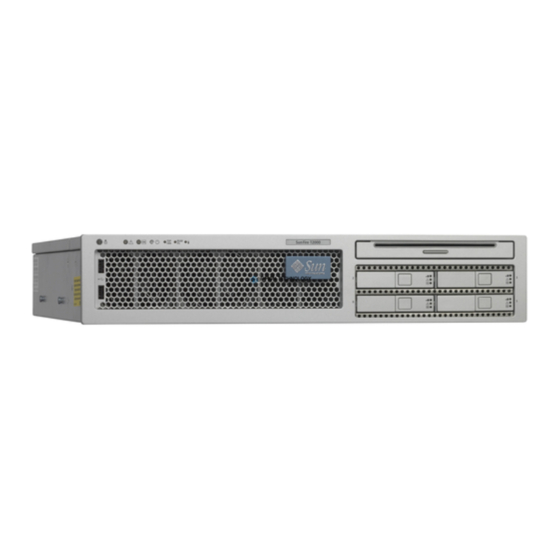
- Page 7 Figures Sun Fire T2000 Server 1 FIGURE 1-1 Rear Panel Features 6 FIGURE 1-2 Front Panel USB Ports 6 FIGURE 1-3 Sections of the Slide Rail Assembly 8 FIGURE 1-4 Locating the Locks on the Slide Rail Assembly 9 FIGURE 1-5 Unlocking the Slide Rail Assembly 12 FIGURE 2-1 Location of the Mounting Bracket Release Button 13...
- Page 8 Front Panel USB Ports 28 FIGURE 2-16 Ethernet Network Connections 28 FIGURE 2-17 System Controller Serial Connection 29 FIGURE 2-18 System Controller Network Connection 30 FIGURE 2-19 Serial Port 31 FIGURE 2-20 Opening a Cable Clip 32 FIGURE 2-21 Removing a Cable Clip 33 FIGURE 2-22 Mounting or Moving a Cable Clip 33 FIGURE 2-23...
- Page 9 Tables Ethernet Connection Transfer Rates 7 TABLE 1-1 Sample Configuration Parameter Settings 41 TABLE 3-1 Map of Devices, OpenBoot Path Names, and Locations 46 TABLE 3-2...
- Page 10 Sun Fire T2000 Server Installation Guide • April 2006...
-
Page 11: Regulatory Compliance Statements
FCC radio frequency emission limits. Networking connections can be made using unshielded twisted-pair (UTP) cables. Modifications: Any modifications made to this device that are not approved by Sun Microsystems, Inc. may void the authority granted to the user by the FCC to operate this equipment. - Page 12 ICES-003 Class A Notice - Avis NMB-003, Classe A This Class A digital apparatus complies with Canadian ICES-003. Cet appareil numérique de la classe A est conforme à la norme NMB-003 du Canada. ICES-003 Class B Notice - Avis NMB-003, Classe B This Class B digital apparatus complies with Canadian ICES-003.
-
Page 13: Bsmi Class A Notice
BSMI Class A Notice The following statement is applicable to products shipped to Taiwan and marked as Class A on the product compliance label. T33012 CCC Class A Notice The following statement is applicable to products shipped to China and marked with “Class A” on the product’s compliance label. - Page 14 Sun Fire T2000 Server Installation Guide • April 2006...
-
Page 15: Declaration Of Conformity
Dennis P. Symanski DATE Donald Cameron DATE Worldwide, Compliance Office Program Manager/Quality Systems Sun Microsystems, Inc. Sun Microsystems Scotland, Limited 4150 Network Circle, MPK15-102 Blackness Road, Phase I, Main Bldg. Santa Clara, CA 95054 U.S.A. Springfield, EH49 7LR Tel: 650-786-3255... - Page 16 Sun Fire T2000 Server Installation Guide • April 2006...
-
Page 17: Preface
Preface The Sun Fire T2000 Server Installation Guide provides instructions, background information, and reference material to help you install a Sun Fire T2000 server. Instructions for installation in the document assume that a system administrator is ™ experienced with the Solaris Operating System (Solaris OS). -
Page 18: Typographic Conventions
Using UNIX Commands ® This document might not contain information about basic UNIX commands and procedures such as shutting down the system, booting the system, and configuring devices. Refer to the following for this information: Software documentation that you received with your system ■... -
Page 19: Related Documentation
* The settings on your browser might differ from these settings. Related Documentation The documents listed as online are available at: http://www.sun.com/documentation Title Description Part Number Sun Fire T2000 Server Site Planning Guide Site planning information for the 819-2545-xx Sun Fire T2000 server Sun Fire T2000 Server Product Notes Late breaking information about the 819-2544-xx... -
Page 20: Sun Welcomes Your Comments
Documentation, Support, and Training Sun Function Description Documentation Download PDF and HTML documents, http://www.sun.com/documentation/ and order printed documents Support and Obtain technical support, download http://www.sun.com/supportraining/ Training patches, and learn about Sun courses Third-Party Web Sites Sun is not responsible for the availability of third-party web sites mentioned in this document. -
Page 21: Preparing For Installation
C H A P T E R Preparing for Installation This chapter provides background information about the Sun Fire™ T2000 server installation procedures that are provided in Chapter This chapter contains these topics: “Tools Needed” on page 2 ■ “Shipping Kit Inventory List” on page 2 ■... -
Page 22: Tools Needed
Tools Needed #2 Phillips screwdriver ■ ESD mat and grounding strap ■ Shipping Kit Inventory List Standard components of Sun Fire T2000 server are installed at the factory. However, if you ordered options such as a PCI card and monitor, these are shipped to you separately. -
Page 23: Esd Precautions
If you ordered any options that are not factory-installed, see the Sun Fire T2000 Server Service Manual for installation instructions. Note – The list of optional components can be updated without notice. Refer to the Store web site (http://store.sun.com) for the most current list of components supported in the Sun Fire T2000 server. - Page 24 4. Mount the server into a rack or cabinet. See “Installing the Server in a Rack” on page Note – In the rest of this manual, the term rack means either an open rack or a closed cabinet. 5. Connect the server to a serial terminal or a terminal emulator (PC or workstation) to display system messages.
-
Page 25: Data Ports And Cabling Notes
12. Configure the Solaris™ OS. See “Booting the Solaris Operating System” on page The Solaris OS is preinstalled on the server. When you power on, you are automatically guided through the Solaris OS configuration procedure. 13. Install any required patch or patches to the server. Refer to the Sun Fire T2000 Server Product Notes for a list of the required patches. -
Page 26: Cabling Notes
PCI-E Slot 2 SC Net Mgt Port PCI-E Slot 1 PCI-X Slot 0 SC Serial Mgt Port PCI-X Slot 1 NET3 USB Port 1 NET2 TTYA Serial Port Power Supply 0 Power Supply 1 PCI-E Slot 0 NET1 NET0 Locator LED button Service Required LED USB Port 0 Power OK LED... - Page 27 The SC serial management port (labeled SERIAL MGT) uses an RJ-45 cable ■ and is always available. This is the default connection to the ALOM-CMT system controller. The SC network management port (labeled NET MGT) is the optional ■ connection to the ALOM-CMT system controller. This port is not available until you have configured network settings for the system controller (through the SC serial management port).
-
Page 28: Slide Rail Assembly Notes
Slide Rail Assembly Notes The rackmount kit has two slide rail assemblies. A slide rail assembly can be installed on either the right or left side of the rack. Each slide rail assembly consists of a three-section slide rail and a removeable mounting bracket ( FIGURE 1-4 Mounting bracket... -
Page 29: Figure 1-5 Locating The Locks On The Slide Rail Assembly
Locating the Locks on the Slide Rail Assembly FIGURE 1-5 Chapter 1 Preparing for Installation... -
Page 30: Safety Precautions
Safety Precautions Caution – Deploy the anti-tilt bar on the cabinet or rack before beginning an installation. Caution – The server weighs approximately 40 lb (18 kg). Two people are required to lift and mount the system into a rack enclosure when using the procedures in this chapter. -
Page 31: Installing The Sun Fire T2000 Server
C H A P T E R Installing the Sun Fire T2000 Server This chapter provides instructions for installing the Sun Fire T2000 server in an open rack or closed cabinet. This chapter contains the following sections: “Installing the Server in a Rack” on page 11 ■... -
Page 32: To Install The Slide Rail Assemblies
To Install the Slide Rail Assemblies ▼ 1. Pull both mounting brackets completely out of their respective slide rails: a. Simultaneously press and hold the upper and lower lock buttons of the slide rail lock ( FIGURE 2-1 Unlocking the Slide Rail Assembly FIGURE 2-1 b. -
Page 33: Figure 2-2 Location Of The Mounting Bracket Release Button
Location of the Mounting Bracket Release Button FIGURE 2-2 d. Press the metal lever (labeled Push) on the middle section ( ) of the FIGURE 2-3 sliding rail, then push the middle section back into the rack. Chapter 2 Installing the Sun Fire T2000 Server... -
Page 34: Figure 2-3 Unlocking The Slide Rail Middle Section
Metal lever Unlocking the Slide Rail Middle Section FIGURE 2-3 2. Attach a mounting bracket to the right side of the Sun Fire T2000 chassis. a. Position the mounting bracket against the server chassis ( ) so that the FIGURE 2-4 slide rail lock is at the front and the three keyed openings on the mounting bracket are aligned with the three locating pins on the side of the chassis. -
Page 35: Figure 2-4 Attaching A Mounting Bracket To The Chassis
Attaching a Mounting Bracket to the Chassis FIGURE 2-4 b. With the heads of the three locating pins protruding though the three keyed openings in the mounting bracket, pull the mounting bracket toward the front of the chassis until the bracket locks into place with an audible click. c. -
Page 36: Figure 2-5 Mounting A Slide Rail
5. Determine which screws you will use to mount the slide rails. If your rack has threaded mounting holes in the rack posts, determine whether the threads are metric or standard. Select the appropriate screws from the package included in the mounting kit. If your rack does not have threaded mounting holes, the mounting screws are secured with a caged nut. -
Page 37: Figure 2-6 Using The Slide Rail Spacing Tool To Adjust The Distance Between The Slide Rails
c. Loosely attach the rear of the slide rail to the rear rack post with two screws. 7. Attach the second slide rail to the left rack posts in a similar manner. Again, do not tighten the screws. 8. Use the slide rail spacing tool to adjust the distance between the slide rails: a. -
Page 38: Figure 2-7 Mounting The Chassis On The Slide Rails
d. At the rear of the rack, repeat Step a through Step c. for the rear ends of the rails. 9. Deploy the anti-tilt bar, if the chassis or rack is so equipped. Caution – The weight of the server on extended slide rails can be enough to overturn a cabinet. -
Page 39: To Install The Cable Management Kit
11. Slide the chassis into the rack. Caution – Verify that the server is securely mounted in the rack, and that the slide rails are locked to the mounting brackets, before continuing. ▼ To Install the Cable Management Kit The cable management assembly (CMA) clips into the ends of the left and right sliding rail assemblies. -
Page 40: Figure 2-8 Inserting The Cma Rail Extension Into The Rear Of The Left Slide Rail
Inserting the CMA Rail Extension Into the Rear of the Left Slide Rail FIGURE 2-8 The right sides of the two CMA arms have hinged extensions. On the manufacturer’s instruction sheet, the smaller extension is called the CMA Connector for Inner Member. It attaches to the right mounting bracket. The larger extension is called the CMA Connector for Outer Member, and attaches to the right sliding rail. -
Page 41: Figure 2-9 Mounting The Inner Cma Connector
Mounting the Inner CMA Connector FIGURE 2-9 3. Insert the larger extension into the end of the right sliding rail ( FIGURE 2-10 Chapter 2 Installing the Sun Fire T2000 Server... -
Page 42: Figure 2-10 Attaching The Outer Cma Connector
Attaching the Outer CMA Connector FIGURE 2-10 4. Insert the hinged plastic connector at the left side of the CMA fully into the CMA rail extension ( FIGURE 2-11 The plastic tab on the CMA rail extension locks the hinged plastic connector in place. -
Page 43: To Verify The Operation Of The Slide Rails And The Cma
Mounting the Left Side of the Slide Rail FIGURE 2-11 To Verify the Operation of the Slide Rails and ▼ the CMA Tip – Two people are needed this procedure: one to move the server in and out of the rack and one to observe the cables and CMA. 1. -
Page 44: Figure 2-12 Unlocking The Slide Rail Assembly
Unlocking the Slide Rail Assembly FIGURE 2-12 3. Inspect the attached cables for any binding or kinks. 4. Verify that the CMA extends fully and does not bind in the slide rails. 5. When the server is fully extended out, release the slide rail lever stops FIGURE 2-13 Push both levers simultaneously and slide the server back into the rack. -
Page 45: Figure 2-13 Unlocking The Slide Rail Lever Stops
Metal lever Unlocking the Slide Rail Lever Stops FIGURE 2-13 6. Simultaneously unlock both slide rail release buttons ( ),and push the FIGURE 2-14 server completely into the rack. Chapter 2 Installing the Sun Fire T2000 Server... -
Page 46: Dismounting The Server
Slide Rail Release Button FIGURE 2-14 The server should stop after approximately 15 inches (40 cm) of travel. 7. Verify that the cables and the CMA retracted without binding. 8. Adjust the cable hangers and CMA as required. Dismounting the Server If it becomes necessary to remove the server from the rack, or to open the server case for maintenance or hardware upgrades, refer to the Sun Fire T2000 Server Service Manual for procedures. -
Page 47: Connecting Cables To The Server
Connecting Cables to the Server “To Connect the Ethernet Network Cables” on page 28 ■ “To Connect the SC Network Management Port” on page 29 ■ “To Connect the SC Serial Management Port” on page 29 ■ “AC Power Cables” on page 30 ■... -
Page 48: To Connect The Ethernet Network Cables
USB Port3 USB Port2 Front Panel USB Ports FIGURE 2-16 ▼ To Connect the Ethernet Network Cables The Sun Fire T2000 has four RJ-45 Gigabit Ethernet network connectors. They are marked NET0, NET1, NET2, and NET3 ( FIGURE 2-17 NET2 NET3 NET0 NET1... -
Page 49: To Connect The Sc Serial Management Port
To Connect the SC Serial Management Port ▼ Use this port for server management. This port is needed to set up the SC network management port, as detailed in “Enabling the System Controller Network Management Port” on page The SC serial management port is marked SER MGT. It is the leftmost RJ-45 port on the rear of the chassis ( FIGURE 2-18 SER MGT... -
Page 50: Ac Power Cables
NET MGT System Controller Network Connection FIGURE 2-19 ● Connect a Category 5 cable from your network switch or hub to the Network Management Port. AC Power Cables Note – Finish the hardware procedures in this chapter, but do not attach the AC power cables yet. -
Page 51: Usb Ports
Serial port (TTYA) Serial Port FIGURE 2-20 Use a null modem cable or an adapter to perform the crossovers given for each connector. If connecting to a serial port on a personal computer, you can use Sun adapter ■ part number 530-3100-01. If connecting to a Sun workstation or server, you can use Sun adapter part ■... -
Page 52: Figure 2-21 Opening A Cable Clip
Opening a Cable Clip FIGURE 2-21 To Move a Cable Clip ▼ 1. To remove a cable clip from the CMA arm, lift the cable clip approximately 3/8 in (10 mm) to free the lower clip lock, then rotate the entire clip about 90 degrees to free the upper clip lock. -
Page 53: Figure 2-22 Removing A Cable Clip
Removing a Cable Clip FIGURE 2-22 2. To insert a cable clip, position the upper and lower clip locks in the slots of the CMA arm, then press the clip down approximately 3/8 in (10 mm). Mounting or Moving a Cable Clip FIGURE 2-23 Chapter 2 Installing the Sun Fire T2000 Server... - Page 54 Sun Fire T2000 Server Installation Guide • April 2006...
-
Page 55: Powering On The System
C H A P T E R Powering On the System This chapter includes instructions for booting the Sun Fire T2000 system and for enabling the system controller network management port. The following topics are discussed: “Powering On the System for the First Time” on page 35 ■... -
Page 56: Figure 3-1 Rear Panel Power Connectors
1. If you have not already done so, connect a terminal or a terminal emulator (PC or workstation) to the SC serial management port. Configure the terminal or terminal emulator with these settings: 9600 baud ■ 8 bits ■ No parity ■... - Page 57 Sample System Controller Output (Continued) CODE EXAMPLE 3-1 TTY External - Internal Loopback Test, PASSED. TTYC - Internal Loopback Test TTYC - Internal Loopback Test, PASSED. TTYD - Internal Loopback Test TTYD - Internal Loopback Test, PASSED..... Full VxDiag Tests - PASSED Status summary Status = 7FFF VxDiag...
-
Page 58: Enabling The System Controller Network Management Port
Enabling the System Controller Network Management Port The system controller network management port is not operational until you configure network settings for the system controller. Configure the system controller in this order: 1. After the system controller boots, access the ALOM-CMT command line interface through the serial management port. -
Page 59: To Configure The System Controller Network Management Port
The sc prompt is displayed at the first time the system controller is booted. The default configuration provides an ALOM-CMT user account called admin. There is no default password, so you must create a password using the system controller (sc) password command. - Page 60 netsc_ipnetmask – Netmask for the system controller subnet ■ netsc_ipaddr – IP Address of the system controller ■ netsc_ipgateway – IP address of the gateway for the subnet ■ if_network – Specified whether the SC is on the network or not ■...
- Page 61 Note – The highlighted parameters must be set according to the specific details of your network configuration for the network management port to function properly. Sample Configuration Parameter Settings TABLE 3-1 parameter value if_network true if_modem false if_emailalerts false netsc_dhcp false xxx.xxx.xx.xx netsc_ipaddr...
-
Page 62: To Reset The System Controller
Sample Configuration Parameter Settings (Continued) TABLE 3-1 parameter value ser_data xx:xx:xx:xx:xx:xx netsc_enetaddr xx:xx:xx:xx:xx:xx sys_enetaddr To Reset the System Controller ▼ After all of the configuration parameters are set, you must reset the system controller for the new values to take affect. ●... -
Page 63: To Log Into The System Controller Using The Network Management Port
Full VxDiag Tests - PASSED Status summary Status = 7FFF VxDiag PASSED POST PASSED LOOPBACK PASSED PASSED EPROM PASSED FRU PROM PASSED ETHERNET PASSED MAIN CRC PASSED BOOT CRC PASSED TTYD PASSED TTYC PASSED MEMORY PASSED MPC885 PASSED Please login: To Log Into the System Controller Using the ▼... -
Page 64: Using The System Controller For Common Operations
% telnet 129.148.40.30 Trying 129.148.40.30... Connected to 129.148.40.30. Escape character is '^]'. Copyright 2003 Sun Microsystems, Inc. All rights reserved. Use is subject to license terms. Sun(tm) Advanced Lights Out Manager 1.0.11 () Please login: 2. Login as admin using the password you previously set. -
Page 65: To Connect To The System Console
/pci@7c0/pci@0: Device c Nothing there /pci@7c0/pci@0: Device d Nothing there /pci@7c0/pci@0: Device e Nothing there /pci@7c0/pci@0: Device f Nothing there Probing I/O buses Sun Fire T200, No Keyboard Copyright 1998-2004 Sun Microsystems, Inc. All rights reserved. Chapter 3 Powering On the System... - Page 66 OpenBoot Ontario FW build_11***PROTOTYPE_BUILD***, 16376 MB memory installed, Serial #51454515. [firmware obp4.x #0] Ethernet address 0:3:ba:ce:a1:3d, Host ID: 83112233. {0} ok To understand the various devices and their path names as represented in the OpenBoot PROM device tree, refer to .
-
Page 67: Booting The Solaris Operating System
Loading ufs-file-system package 1.4 04 Aug 1995 13:02:54. FCode UFS Reader 1.12 00/07/17 15:48:16. Loading: /platform/SUNW,Ontario/ufsboot Loading: /platform/sun4v/ufsboot SunOS Release 5.10 Version /net/spa/export/spa2/ws/pothier/grlks10-ontario:12/01/2004 64-bit Copyright 1983-2004 Sun Microsystems, Inc. All rights reserved. Use is subject to license terms. Chapter 3 Powering On the System... -
Page 68: To Reset The System
DEBUG enabled misc/forthdebug (159760 bytes) loaded /platform/sun4v/kernel/drv/sparcv9/px symbol intr_devino_to_sysino multiply defined os-tba FPU not in use configuring IPv4 interfaces: ipge0. Hostname: wgs94-181 The system is coming up. Please wait. NIS domain name is Ecd.East.Sun.COM starting rpc services: rpcbind keyserv ypbind done. Setting netmask of lo0 to 255.0.0.0 Setting netmask of bge0 to 255.255.255.0 Setting default IPv4 interface for multicast: add net 224.0/4:... - Page 69 At the Solaris OS prompt, issue the uadmin command to halt the Solaris OS and to return to the ok prompt. # uadmin 2 0 WARNING: proc_exit: init exited syncing file systems... done Program terminated 2. Switch from the system console prompt to the SC console prompt by issuing the #. escape sequence.
- Page 70 Sun Fire T2000 Server Installation Guide • April 2006...
-
Page 71: Updating The Firmware
A P P E N D I X Updating the Firmware The flashupdate command updates both the service processor firmware and the host firmware. The flash image consists of the following components: System controller firmware ■ OpenBoot ■ POST ■ Reset/Config ■... - Page 72 2. Open a Telnet session and connect to the system controller, as in the following example. % telnet 129. Trying 129.xxx.xx.xx... Connected to 129.xxx.xx.xx. Escape character is’^]’. Use is subject to license terms. Symptom) Advanced Lights Out Manager 1.0.11 () Please login: Substitute the IP address of your system controller.
- Page 73 -v is the flag to turn on verbose message output ■ sc> flashupdate -s 129.xxx.xx.xx -f / net/macross.east/export/data5/ontario/debug/golden/latestbuild/ combined-OSP-image-1.0.7 Username: debug Password: password ..............Update complete. Reset device to use new image. sc> 5. Reset the system controller. After the flash has been updated, you must reset the system controller for the new image to take affect.
- Page 74 The system controller resets, runs diagnostics, and returns to the login prompt. The following example is for the serial console. ALOM POST 1.0 Dual Port Memory Test, PASSED. TTY External - Internal Loopback Test TTY External - Internal Loopback Test, PASSED. TTYC - Internal Loopback Test TTYC - Internal Loopback Test, PASSED.
-
Page 75: Selecting A Boot Device
This procedure assumes that you are familiar with the OpenBoot firmware and that you know how to enter the OpenBoot environment. For more information, see the Sun Fire T200 Server Administration Guide. Note – The serial management port on the ALOM card is preconfigured as the default system console port. - Page 76 net, net0, net1, net2, net3 – Specifies the network interfaces ■ full path name – Specifies the device or network interface by its full path name ■ Note – The Solaris OS modifies the boot-device variable to its full path name, not the alias name.
-
Page 77: Index
Index Symbols #. escape sequence for system console, 49 cable clip, using, 31 to 33 ^] escape character for telnet, 44 cable management assembly, 19 to 26 CCC class A notice, xiii CE mark, xv AC power cables and standby mode, 30 certification mark, GOSTR, xiii accessing ALOM-CMT command line, 38 CMA, See cable management assembly... - Page 78 example configuration for network management logging into system controller port, 41 using network management port, 38, 43 using serial management port, 38 FCC notice class A certification, xv manuals online, xx class A notice, xi map of OpenBoot PROM devices, 46 class B notice, xi minimum cable connections, 6 feedback comments and suggestions, xx...
- Page 79 power supply locations illustrated, 27 standby voltage causes system controller to power on, 4 powering on the system for the first time, 35 standby voltage, 3.3v, 35 poweroff command, 49 stop bit, 36 poweron command, 44, 49 support online, xx product notes, xix system administration guide, xix system console escape sequence #., 49...
- Page 80 Sun Fire T2000 Server Installation Guide • April 2006...
Need help?
Do you have a question about the Sun Fire T200 and is the answer not in the manual?
Questions and answers