Sun Microsystems Fire T2000 Service Manual
Hide thumbs
Also See for Fire T2000:
- Installation manual (116 pages) ,
- Administration manual (122 pages) ,
- Service manual (166 pages)

Related Manuals for Sun Microsystems Fire T2000


Summary of Contents for Sun Microsystems Fire T2000
-
Page 1: Service Manual
Sun Fire T2000 Server ™ Service Manual Sun Microsystems, Inc. www.sun.com Part No. 819-2548-10 October 2005, Revision A Submit comments about this document at: http://www.sun.com/hwdocs/feedback... - Page 2 Copyright 2005 Sun Microsystems, Inc., 4150 Network Circle, Santa Clara, Californie 95054, Etats-Unis. Tous droits réservés. Sun Microsystems, Inc. a les droits de propriété intellectuels relatants à la technologie qui est décrit dans ce document. En particulier, et sans la limitation, ces droits de propriété...
-
Page 3: Table Of Contents
Error Correction and Parity Checking 7 Predictive Self Healing 7 Chassis Identification 9 Additional Service Related Information 10 Sun Fire T2000 Server Diagnostics 11 Overview of Sun Fire T2000 Server Diagnostics 12 Using LEDs to Identify the State of Devices 16... - Page 4 ▼ To View System Message Log Files 43 Managing Components with Automatic System Recovery (ASR) Commands 44 ▼ To Run the showcomponent Command 46 ▼ To Run the disablecomponent Command 47 Sun Fire T2000 Server Service Manual • October 2005...
- Page 5 ▼ To Run the enablecomponent Command 47 Exercising the System With SunVTS 48 Checking Whether SunVTS Software Is Installed 48 ▼ To Check Whether SunVTS Software Is Installed 48 Exercising the System Using SunVTS Software 50 ▼ To Exercise the System Using SunVTS Software 50 For further information, refer to the manuals that accompany the SunVTS software 53 Replacing Hot-Swappable and Hot-Pluggable FRUs 55...
- Page 6 To Replace the Fan Power Board 96 ▼ To Remove the Front I/O Board 96 ▼ To Replace the Front I/O Board 97 ▼ To Remove the DVD Drive 98 ▼ To Replace the DVD Drive 99 Sun Fire T2000 Server Service Manual • October 2005...
- Page 7 ▼ To Remove the SAS Disk Backplane 99 ▼ To Replace the SAS Disk Backplane 100 ▼ To Remove the Battery on the System Controller 101 ▼ To Replace the Battery on the System Controller 101 Common Procedures for Finishing Up 103 ▼...
- Page 8 Sun Fire T2000 Server Service Manual • October 2005...
-
Page 9: Preface
Preface The Sun Fire T2000 Service Manual provides information to aid in diagnosing hardware problems and describes how to replace components within the Sun Fire™ T2000 server. This guide also describes how to add components such as hard drives and memory to the server. -
Page 10: How This Book Is Organized
How This Book Is Organized This guide is organized into the following chapters: Chapter 1 describes the main features of the Sun Fire T2000 server. Chapter 2 describes the diagnostics that are available for monitoring and diagnosing the Sun Fire T2000 server. - Page 11 Sun Fire T2000 Server How to perform administrative tasks that 819-2549 Administration Guide are specific to the Sun Fire T2000 server Sun Fire T2000 Server Advanced How to use the Advanced Lights Out 819-2550 Lights Out Manager (ALOM) Guide...
-
Page 12: Typographic Conventions
Bourne shell and Korn shell Bourne shell and Korn shell superuser Accessing Sun Documentation You can view, print, or purchase a broad selection of Sun documentation, including localized versions, at: http://www.sun.com/documentation xii Sun Fire T2000 Server Service Manual • October 2005... -
Page 13: Contacting Sun Technical Support
Sun is interested in improving its documentation and welcomes your comments and suggestions. You can submit your comments by going to: http://www.sun.com/hwdocs/feedback Please include the title and part number of your document with your feedback: Sun Fire T2000 Server Service Manual, part number 819-2548-10 Preface xiii... - Page 14 Sun Fire T2000 Server Service Manual • October 2005...
-
Page 15: Sun Fire T2000 Server Overview
C H A P T E R Sun Fire T2000 Server Overview This chapter provides an overview of the features of the Sun Fire T2000 server. The following topics are covered: “Sun Fire T2000 Server Features” on page 2 ■... -
Page 16: Sun Fire T2000 Server Features
Sun Fire T2000 Server Features The Sun Fire T2000 server is a high-performance entry-level server that is highly scalable and extremely reliable. Sun Fire T2000 Server FIGURE 1-1 Chip-Multitheaded (CMT) Multicore Processor and Memory Technology ® The UltraSPARC T1 multicore processor is the basis of the Sun Fire T2000 server. - Page 17 Additional processor components, such as L1 cache, L2 cache, memory access crossbar, DDR2 memory controllers, and a JBus I/O interface have been carefully tuned for optimal performance. UltraSPARC T1 multicore processor Motherboard and UltraSPARC T1 Multicore Processor FIGURE 1-2 Chapter 1 Sun Fire T2000 Server Overview...
-
Page 18: Performance Enhancements
Solaris 10 3/05 HW2 Operating System preinstalled on disk 0 Other software Java™ Enterprise System with a 90-day trial license * Check the Sun Fire T2000 Product Notes for the latest information about supported releases of the Solaris OS. Sun Fire T2000 Server Service Manual • October 2005... -
Page 19: Remote Manageability With Alom
The Sun Advanced Lights Out Manager (ALOM) feature is a system controller (SC) that enables you to remotely manage and administer the Sun Fire T2000 server. The ALOM software is preinstalled as firmware, and it initializes as soon as you apply power to the system. -
Page 20: Hot-Pluggable And Hot-Swappable Components
The Sun Fire T2000 server also has a single hot-swappable blower unit that works in conjunction with the power supply fans to provide cooling for the internal disk drives. -
Page 21: Environmental Monitoring
Sun systems to accurately predict component failures and mitigate many serious problems before they actually occur. This technology is incorporated into both the hardware and software of the Sun Fire T2000 server. Chapter 1 Sun Fire T2000 Server Overview... - Page 22 By automatically diagnosing problems, business-critical applications and essential system services can continue uninterrupted in the event of software failures, or major hardware component failures. Sun Fire T2000 Server Service Manual • October 2005...
-
Page 23: Chassis Identification
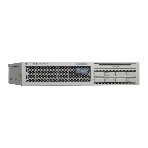
Chassis Identification show the physical characteristics of the Sun Fire T2000 FIGURE 1-3 FIGURE 1-4 server. Indicators and buttons DVD drive Drive 2 Drive 3 Drive 0 Drive 1 USB ports Hard drives Sun Fire T2000 Server Front Panel FIGURE 1-3... -
Page 24: Additional Service Related Information
In addition to this service manual, the following resources are available to help you keep your server running optimally: Product Notes – The Sun Fire T2000 Server Product Notes (819-2544) contain late ■ breaking information about the system including required software patches, updated hardware and compatibility information, and solutions to know issues. -
Page 25: Sun Fire T2000 Server Diagnostics
Sun Fire T2000 Server Diagnostics This chapter describes the diagnostics that are available for monitoring and troubleshooting the Sun Fire T2000 server. This chapter does not provide troubleshooting methods, but instead describes the Sun Fire T2000 server diagnostics facilities and describes how to use them. -
Page 26: Overview Of Sun Fire T2000 Server Diagnostics
The flowchart assumes that you have already performed some rudimentary troubleshooting such as verification of proper installation, visual inspection of cables and power, and possibly performed a reset of the server (refer to the Sun Fire T2000 Server Installation Guide and Sun Fire T2000 Server Administration Guide for details). - Page 27 Replace Faulty recommended actions Did the article recom- Verify the mend a FRU Perform recom- repair replacement? mended corrective actions. If needed, contact Sun for Support Diagnostic Flow Chart FIGURE 2-1 Chapter 2 Sun Fire T2000 Server Diagnostics...
- Page 28 From Solaris OS Files and information. faults. Commands” on page 43 • If system messages indicate a faulty device, replace the FRU (Action 9). • To obtain more diagnostic information, got to Action 7. Sun Fire T2000 Server Service Manual • October 2005...
- Page 29 Sun Support information: Support. server’s diagnostics. In rare cases it is possible that http://www.sun.com/ a problem requires additional troubleshooting. If service/contacting you are unable to determine the cause of the problem, contact Sun for support. Chapter 2 Sun Fire T2000 Server Diagnostics...
-
Page 30: Using Leds To Identify The State Of Devices
Using LEDs to Identify the State of Devices The Sun Fire T2000 server provides the following groups of LEDs: Front and Rear Panel LEDs ■ TABLE 2-2 Power Supply LEDs TABLE 2-4 ■ Fan LEDs ■ TABLE 2-5 Hard Drive LEDs ■... - Page 31 • Slow blink – Indicates that a normal transitory activity is taking place. It might mean that the system diagnostics are running, or that the system is booting. Chapter 2 Sun Fire T2000 Server Diagnostics...
- Page 32 View the ALOM reports for further information on this event. * Provided on the front and rear panel, otherwise the LED is only located on the front panel. Sun Fire T2000 Server Service Manual • October 2005...
-
Page 33: Hard Drive Leds
Hard Drive LEDs The hard drive LEDs ( ) are located on the front of each hard FIGURE 2-4 TABLE 2-3 drive that is installed in the Sun Fire T2000 server chassis. OK to Remove unused Activity Hard Drive LEDs... -
Page 34: Power Supply Leds
On – Power supply has detected a failure. Off – Normal operation. AC OK Green On – Normal operation. Input power is within normal limits. Off – No input voltage, or input voltage is below limits. Sun Fire T2000 Server Service Manual • October 2005... -
Page 35: Fan Leds
Blower Unit LED TABLE 2-6 Color Description Blower Unit Amber On – The blower unit is faulty. Off – Normal operation. Note: When a blower fault is detected the Rear-FRU Fault LED is lit. Chapter 2 Sun Fire T2000 Server Diagnostics... -
Page 36: Using Alom For Diagnosis And Repair Verification
Therefore, ALOM firmware and software continue to function when the server operating system goes offline or when the server is powered off. Note – Refer to the Sun Fire T2000 Server Advanced Lights Out Manager (ALOM) Guide for comprehensive ALOM information. - Page 37 There is no ALOM command to manually repair an environmental fault. ALOM does not handle hard drive faults. Use the Solaris message files to view hard drive faults. See “Collecting Information From Solaris OS Files and Commands” on page Chapter 2 Sun Fire T2000 Server Diagnostics...
-
Page 38: Running Alom Service-Related Commands
Connect an external modem to the network management port and dial-in to the ■ modem. Note – Refer to the Sun Fire T2000 Server Advanced Lights Out Manager (ALOM) Guide for instructions on configuring and connecting to ALOM. Switching Between the System Console and ALOM To switch from the console output to the ALOM sc>... -
Page 39: Service-Related Alom Commands
ALOM commands for servicing a Sun Fire T2000 TABLE 2-7 server. For descriptions of all ALOM commands, issue the help command or refer to the Sun Fire T2000 Server Advanced Lights Out Management (ALOM) Guide. Service-Related ALOM Commands TABLE 2-7... -
Page 40: To Run The Showfaults Command
2. Use the Sun message ID to obtain more information about the fault. In a browser, go to the Predictive Self-Healing Knowledge Article web site: http://www.sun.com/msg and enter the Sun message ID in the lookup field. Sun Fire T2000 Server Service Manual • October 2005... -
Page 41: To Run The Showenvironment Command
Temp LowHard LowSoft LowWarn HighWarn HighSoft HighHard ------------------------------------------------------------------------------ PDB/T_AMB MB/T_AMB MB/CMP0/T_TCORE MB/CMP0/T_BCORE IOBD/IOB/TCORE IOBD/T_AMB -------------------------------------------------------- System Indicator Status: -------------------------------------------------------- SYS/LOCATE SYS/SERVICE SYS/ACT -------------------------------------------------------- SYS/REAR_FAULT SYS/TEMP_FAULT SYS/TOP_FAN_FAULT -------------------------------------------------------- -------------------------------------------- System Disks: -------------------------------------------- Disk Status Service OK2RM Chapter 2 Sun Fire T2000 Server Diagnostics... - Page 42 10.20 10.80 13.20 13.80 SC/BAT/V_BAT 3.03 2.69 ----------------------------------------------------------- System Load (in amps): ----------------------------------------------------------- Sensor Status Load Warn Shutdown ----------------------------------------------------------- MB/I_VCORE 25.280 80.000 88.000 MB/I_VMEML 4.680 60.000 66.000 MB/I_VMEMR 4.680 60.000 66.000 Sun Fire T2000 Server Service Manual • October 2005...
-
Page 43: To Run The Showfru Command
The showfru command displays information about the FRUs in the server. Use this command to see information about an individual FRU, or for all the FRUs. Note – By default, the output of the showfru command for all FRUs is very long. Chapter 2 Sun Fire T2000 Server Diagnostics... - Page 44 /ManR/Sun Serial No: NC00OD /ManR/Vendor: Celestica /ManR/Initial HW Dash Level: 06 /ManR/Initial HW Rev Level: /ManR/Shortname: T2000_MB /SpecPartNo: 885-0483-04 SEGMENT: FL /Configured_LevelR /Configured_LevelR/UNIX_Timestamp32: WED OCT 12 18:24:28 2005 /Configured_LevelR/Sun_Part_No: 5410827 /Configured_LevelR/Configured_Serial_No: N4001A /Configured_LevelR/HW_Dash_Level: Sun Fire T2000 Server Service Manual • October 2005...
-
Page 45: Running Post
The system cannot power on. stby The system can power on and run POST, but no locked flash updates can be made. POST does not run. diag_mode Runs POST according to diag_level value. normal Chapter 2 Sun Fire T2000 Server Diagnostics... - Page 46 POST output displays all test and informational normal messages. POST displays all test, informational, and some debugging messages. * All of these parameters are set using the ALOM setsc command except for the setkeyswitch command. Sun Fire T2000 Server Service Manual • October 2005...
- Page 47 Flowchart of ALOM Variables for POST Configuration FIGURE 2-7 Chapter 2 Sun Fire T2000 Server Diagnostics...
-
Page 48: To Change Post Parameters
2. At the ALOM sc> prompt, use the setsc command to set the POST parameter: Example: sc> setsc diag_mode service The setkeyswitch parameter is a command that sets the virtual keyswitch, so it does not use the setsc command. Example: sc> setkeyswitch diag Sun Fire T2000 Server Service Manual • October 2005... -
Page 49: Reasons To Run Post
1. Switch from the system console prompt to the SC console prompt by issuing the #. escape sequence. ok #. sc> 2. Set the virtual keyswitch to diag so that POST will run in service mode. sc> setkeyswitch diag Chapter 2 Sun Fire T2000 Server Diagnostics... - Page 50 3. Reset the system so that POST runs. There are several ways to initiate a reset. The following example uses the powercycle command. For other methods, refer to the Sun Fire T2000 Server Administration Guide. sc> powercycle Are you sure you want to powercycle the system [y/n]? y Powering host off at MON JAN 10 02:52:02 2000 Waiting for host to Power Off;...
- Page 51 1 2 3 ] Rank 0 Stack 0 0:0>..0:0>Test 4294967296 bytes at 00000001.00000000 Memory Channel [ 0 1 2 3 ] Rank 1 Stack 0 0:0>..0:0>IO-Bridge Tests..0:0>IO-Bridge Quick Read 0:0> 0:0>------------------------------------------------------------ Chapter 2 Sun Fire T2000 Server Diagnostics...
- Page 52 > MSG = test_error_message c:s > END_ERROR In this syntax, c = the core number, s = the strand number. Warning and informational messages use the following syntax: INFO or WARNING: message Sun Fire T2000 Server Service Manual • October 2005...
- Page 53 Note – You can use ASR commands to display and control disabled components. “Managing Components with Automatic System Recovery (ASR) Commands” on page Chapter 2 Sun Fire T2000 Server Diagnostics...
-
Page 54: Using The Solaris Predictive Self-Healing Feature
Using the Solaris Predictive Self-Healing Feature The Solaris predictive self-healing (PSH) technology enables Sun Fire T2000 server to diagnose problems while the Solaris OS is running, and mitigate many problems before they occur. The Solaris OS uses the fault manager daemon, fmd(1M), which starts at boot time and runs in the background to monitor the system. -
Page 55: To Use The Fmdump Command To Identify Faults
MB, indicating that the motherboard requires replacement. 2. Use the Sun message ID to obtain more information about this type of fault. a. In a browser, go to the Predictive Self-Healing Knowledge Article web site: http://www.sun.com/msg Chapter 2 Sun Fire T2000 Server Diagnostics... - Page 56 CPU. The recommended action for the system administrator is to contact Sun support so a Sun service technician can replace the affected component. c. Follow the suggested actions to repair the fault. Sun Fire T2000 Server Service Manual • October 2005...
-
Page 57: Collecting Information From Solaris Os Files And Commands
Collecting Information From Solaris OS Files and Commands With the Solaris OS running on the Sun Fire T2000 server, you have the full compliment of Solaris OS files and commands available for collecting information and for troubleshooting. In the event that POST, ALOM, or the Solaris PSH features did not indicate the source of a fault, check the message buffer and log files for notifications for faults. -
Page 58: Managing Components With Automatic System Recovery (Asr) Commands
The Automatic System Recovery (ASR) feature enables the server to automatically configure failed components out of operation until they can be replaced. In the Sun Fire T2000 server, the following components managed by the ASR feature: UltraSPARC T1 processor strands ■... - Page 59 Note – A reset or powercycle is required after disabling or enabling a component. If the status of a component is changed with power on there is no effect to the system until the next reset or powercycle. Chapter 2 Sun Fire T2000 Server Diagnostics...
-
Page 60: To Run The Showcomponent Command
MB/CMP0/CH3/R0/D0 MB/CMP0/CH3/R0/D1 MB/CMP0/CH3/R1/D0 MB/CMP0/CH3/R1/D1 IOBD/PCIEa IOBD/PCIEb PCIX1 PCIX0 PCIE2 PCIE1 PCIE0 TTYA ASR state: clean Example showing a disabled component: sc> showcomponent ASR state: Disabled Devices MB/CMP0/CH3/R1/D1 : dimm15 deemed faulty Sun Fire T2000 Server Service Manual • October 2005... -
Page 61: To Run The Disablecomponent Command
1. At the sc> prompt, enter the enablecomponent command. sc> enablecomponent MB/CMP0/CH3/R1/D1 sc>SC Alert:MB/CMP0/CH3/R1/D1 reenabled 2. After receiving confirmation that the enablecomponent command is complete, reset the server for so that the ASR command takes effect. sc> reset Chapter 2 Sun Fire T2000 Server Diagnostics... -
Page 62: Exercising The System With Sunvts
“Exercising the System Using SunVTS Software” on page 50 ■ Checking Whether SunVTS Software Is Installed This procedure assumes that the Solaris OS is running on the Sun Fire T2000 server, and that you have access to the Solaris command line. To Check Whether SunVTS Software Is Installed ▼... - Page 63 From the Sun Download Center: http://www.sun.com/oem/products/vts ■ The SunVTS 6.0 PS3 software, and future compatible versions, are supported on the Sun Fire T2000 server. SunVTS installation instructions are described in the SunVTS User’s Guide. Chapter 2 Sun Fire T2000 Server Diagnostics...
-
Page 64: Exercising The System Using Sunvts Software
SunVTS software can be run in several modes. This procedure assumes that you are using the default mode. This procedure also assumes that the Sun Fire T2000 server is headless—that is, it is not equipped with a monitor capable of displaying bit mapped graphics. In this case, you access the SunVTS GUI by logging in remotely from a machine that has a graphics display. - Page 65 3. Remotely log in to the Sun Fire T2000 server as superuser. Use a command such as rlogin or telnet. 4. Start SunVTS software. If you have installed SunVTS software in a location other than the default /opt directory, alter the path in the preceding command accordingly.
- Page 66 Tests are enabled when checked, and disabled when not checked. lists tests that are especially useful to run on a Sun Fire T2000 server. TABLE 2-11 Useful SunVTS Tests to Run on a Sun Fire T2000 Server...
-
Page 67: For Further Information, Refer To The Manuals That Accompany The Sunvts Software
– ■ generated by the operating system and various applications. Log Files (/var/opt/SUNWvts/logs) A directory containing the log files. – ■ For further information, refer to the manuals that accompany the SunVTS software Chapter 2 Sun Fire T2000 Server Diagnostics... - Page 68 Sun Fire T2000 Server Service Manual • October 2005...
-
Page 69: Replacing Hot-Swappable And Hot-Pluggable Frus
Replacing Hot-Swappable and Hot- Pluggable FRUs This chapter describes how to remove and replace the hot-swappable and hot- pluggable field replaceable units (FRUs) in the Sun Fire T2000 Server. The following topics are covered: “Devices That Are Hot-Swappable and Hot-Pluggable” on page 56 ■... -
Page 70: Devices That Are Hot-Swappable And Hot-Pluggable
Hot-Swapping a Fan Three hot-swappable fans are located under the fan door. Two working fans are required to provide adequate cooling for the Sun Fire T2000 server. If a fan fails, replace it as soon as possible to ensure system availability. -
Page 71: To Remove A Fan
To Remove a Fan ▼ 1. Gain access to the top of the server where the fan door is located ( FIGURE 3-1 You might need to extend the server to a maintenance position. See “To Extend the Server to the Maintenance Position” on page 69 Latch Fan door Removing a Fan... -
Page 72: Hot-Swapping A Power Supply
5. If necessary, return the server to its normal position in the rack. Hot-Swapping a Power Supply The Sun Fire T2000 server’s redundant hot-swappable power supplies enable you to remove and replace a power supply without shutting the server down provided that the other power supply is online and working. - Page 73 2. At the sc> prompt, issue the removefru command. The removefru command prepares the server for the hot swap operation. For instructions on how to access the sc> prompt, refer to the Sun Fire T2000 Server Advanced Lights Out Manager (ALOM) Guide.
-
Page 74: To Replace A Power Supply
5. Verify that the amber LED on the replaced power supply, the Service required, and Rear-FRU Fault LEDs are not lit. 6. At the sc> prompt, issue the showenvironment command to verify the status of the power supplies. Sun Fire T2000 Server Service Manual • October 2005... -
Page 75: Hot-Swapping The Rear Blower
Hot-Swapping the Rear Blower The rear blower on the Sun Fire T2000 server is hot-swappable. The following LEDs are lit when a blower unit fault is detected: Front and rear Service Required LEDs ■ LED on the blower is lit. - Page 76 3. Tighten the two thumbscrews to secure the blower (FN2)to the chassis. 4. Verify that the Rear Blower and Service Required LEDs are not lit. 5. Close the CMA, inserting the end of the CMA into the rear left rail bracket. Sun Fire T2000 Server Service Manual • October 2005...
-
Page 77: Hot-Plugging A Hard Drive
Hot-Plugging a Hard Drive The hard disk drives in the Sun Fire T2000 server are hot-pluggable, but this capability depends on how the hard drives are configured. To hot plug a drive you must be able to take the drive offline (prevent any applications from accessing it, and remove the logical software links to it) before you can safely remove it. -
Page 78: To Replace A Hard Drive
The procedures that you perform at this point depend on how your data is configured. You might need to partition the drive, create file systems, load data from backups, or have it updated from a RAID configuration. Example: cfgadm -c configure c0t0d0s0 Sun Fire T2000 Server Service Manual • October 2005... -
Page 79: Replacing Cold Swappable Frus
C H A P T E R Replacing Cold Swappable FRUs This chapter describes how to remove and replace field replaceable units (FRUs) in the Sun Fire T2000 server that must be cold swapped. The following topics are covered: “Safety Information” on page 66 ■... -
Page 80: Safety Information
Safety Information This section describes important safety information you need to know prior to removing or installing parts in the Sun Fire T2000 server. For your protection, observe the following safety precautions when setting up your equipment: Follow all Sun standard cautions, warnings, and instructions marked on the ■... -
Page 81: Electrostatic Discharge Safety
Common Procedures for Parts Replacement Before you can remove and replace parts that are inside the Sun Fire T2000 server, you must perform the following procedures: “To Shut the System Down” on page 68 ■... -
Page 82: Required Tools
The corresponding procedures that you perform when maintenance is complete are described in “Common Procedures for Finishing Up” on page 103. Required Tools The Sun Fire T2000 server can be serviced with the following tools: Antistatic wrist strap ■ Antistatic mat ■... -
Page 83: To Extend The Server To The Maintenance Position
This button is recessed to prevent accidental server power-off. Use the tip of a pen to operate this button. Refer to the Sun Fire T2000 Server Advanced Lights Out Management (ALOM) Guide for more information about the ALOM poweroff command. -
Page 84: To Remove The Server From The Rack
CMA from the rail assembly (on the right side from the back of the rack). This leaves the CMA still attached to the cabinet, but the server chassis is now disconnected from the CMA. Sun Fire T2000 Server Service Manual • October 2005... - Page 85 Locating the Metal Lever FIGURE 4-2 Caution – The server weighs approximately 40 lb. (18 kg). The next step requires two people to dismount and carry the chassis. 4. From the front of the server, pull the release tabs forward and pull the server forward until it is free of the rack rails.
-
Page 86: To Disconnect Power From The Server
Do this after you disconnect the power cords from the server. ▼ To Remove the Top Cover All field replaceable units (FRUs) that are not hot swappable require the removal of the top cover. Sun Fire T2000 Server Service Manual • October 2005... -
Page 87: To Remove The Front Bezel And Top
1. Press the Top cover release button ( FIGURE 4-3 Top cover Fan cover Top cover release button Top front cover cover latch Top Cover and Release Button FIGURE 4-3 2. While pressing the top cover release button, slide the cover toward the rear of the server about half of an inch. -
Page 88: Removing And Replacing Frus
“To Remove the Motherboard Assembly” on page 84 “To Replace the ■ Motherboard Assembly” on page 88 “To Remove the Power Distribution Board” on page 90 “To Replace the ■ Power Distribution Board” on page 92 Sun Fire T2000 Server Service Manual • October 2005... -
Page 89: To Remove Pci-E And Pci-X Cards
“To Remove the LED Board” on page 93 “To Remove the LED Board” on ■ page 93 “To Remove the Fan Power Board” on page 95 “To Replace the Fan Power ■ Board” on page 96 “To Remove the DVD Drive” on page 98 “To Replace the DVD Drive”... - Page 90 4. Make note of and remove any cables that are attached to the card. 5. Rotate the PCI hold-down bracket 90 degrees so it no longer covers the PCI card FIGURE 4-7 PCI hold-down bracket PCI Card and Hold-down Bracket FIGURE 4-7 Sun Fire T2000 Server Service Manual • October 2005...
-
Page 91: To Replace Pci Cards
6. Carefully work the card out of the socket. 7. Place the card on an antistatic mat. 8. Rotate the hold-down bracket so that it does not protrude into the chassis. To Replace PCI Cards ▼ Use this procedure to replace PCI-E and PCI-X cards. 1. - Page 92 TABLE 4-1 DIMM Name Used in Messages Socket No. DIMM No. J0901 DIMM 1 CH0/R1/D1 J0701 DIMM 2 CH0/R0/D1 J0801 DIMM 3 CH0/R1/D0 J0601 DIMM 4 CH0/R0/D0 J1401 DIMM 5 CH1/R0/D1 Sun Fire T2000 Server Service Manual • October 2005...
-
Page 93: To Replace Dimms
DIMM Names and Socket Numbers (Continued) TABLE 4-1 DIMM Name Used in Messages Socket No. DIMM No. J1201 DIMM 6 CH1/R1/D1 J1301 DIMM 7 CH1/R1/D0 J1101 DIMM 8 CH1/R0/D0 J1901 DIMM 16 CH2/R1/D1 J1701 DIMM 15 CH2/R0/D1 J1801 DIMM 14 CH2/R1/D0 J1601 DIMM 13... - Page 94 6. Perform the following steps to clear the memory fault. a. Gain access to the ALOM sc> prompt. Refer to the Sun Fire T2000 Server Advanced Lights Out Management (ALOM) Guide for instructions. b. Run the showfaults -v command to determine how to clear the fault: If the fault is a Host-detected fault (displays a UUID), such as the following: ■...
- Page 95 b. Issue the poweron command. sc> poweron c. Switch to the system console to view POST output. sc> console Watch the POST output for possible fault messages. The following output is a sign that POST did not detect any faults: 0:0>POST Passed all devices.
-
Page 96: To Remove The System Controller
PROM is removed and installed in the replacement system controller. The PROM does not hold the fault data, and this data will no longer be accessible when the system controller is replaced. Sun Fire T2000 Server Service Manual • October 2005... -
Page 97: To Replace The System Controller Board
System configuration PROM Locating the System Configuration PROM FIGURE 4-10 ▼ To Replace the System Controller Board 1. Unpackage the replacement system controller board and place it on an antistatic mat. 2. Install the system configuration PROM that you removed from the faulty system controller board. -
Page 98: To Remove The Motherboard Assembly
Ensure that you remove all cables as well as the power cords. 3. Remove any PCI option cards that are installed and then rotate the hold-down brackets so they do not protrude into the chassis. Sun Fire T2000 Server Service Manual • October 2005... - Page 99 4. Remove all DIMMs. See “To Remove DIMMs” on page 77 from the motherboard assembly. Make note of the memory configuration so you can reinstall the memory in the replacement board. 5. Remove the system controller board from the motherboard assembly See “To Remove the System Controller”...
- Page 100 Location of the Screws in the Motherboard Assembly FIGURE 4-13 8. Slide the motherboard assembly forward to disengage the connectors at the rear of the motherboard assembly from the cutouts in the rear of the chassis. Sun Fire T2000 Server Service Manual • October 2005...
- Page 101 9. Using the handle, tilt the motherboard assembly over the interior chassis wall and lift it out of the chassis ( FIGURE 4-14 Caution – Do not lift the motherboard assembly over the front fan housing to remove it from the chassis because doing so can damage the assembly. Removing the Motherboard Assembly from the Server Chassis.
-
Page 102: To Replace The Motherboard Assembly
Installing the Motherboard Assembly FIGURE 4-15 3. Adjust the position of the motherboard assembly so that it is mounted on the bus bar. Sun Fire T2000 Server Service Manual • October 2005... - Page 103 4. Adjust the position of the motherboard assembly so that it lines up with the standoff screw holes. 5. Loosely install two screws (1 and 2) in the bus bar ( FIGURE 4-16 Bus bar screws Securing the Motherboard Assembly to the Chassis FIGURE 4-16 6.
-
Page 104: To Remove The Power Distribution Board
To disengage a power supply, push the power supply latch to the right and pull the power supply out a few inches to disengage it from the power distribution board FIGURE 4-17 Power supply latches Location of Power Supply Latch FIGURE 4-17 Sun Fire T2000 Server Service Manual • October 2005... - Page 105 3. Disconnect all cables from the power distribution board: Disconnect the hard drive power connector from the power distribution board. ■ Release the latches on the DVD cable and disconnect it. ■ Disconnect the cable marked P7. ■ Disconnect the blower power cable from the power distribution board. ■...
-
Page 106: To Replace The Power Distribution Board
2. Secure the power distribution board to the chassis with the mounting screw. Do not tighten the screw yet. 3. Secure the power distribution board to the bus bar with two screws, and tighten all three screws ( FIGURE 4-20 Sun Fire T2000 Server Service Manual • October 2005... -
Page 107: To Remove The Led Board
Note – After replacing the power distribution board and powering on the system, you must run the setcsn command on the ALOM console to set the electronically readable chassis serial number. For details, refer to the Sun Fire T2000 Server Lights Out Management (ALOM) Guide. -
Page 108: To Replace The Led Board
3. Secure the LED board to the chassis using two M3x6 flat-head screws ( FIGURE 4-21 4. Replace all three fans. “To Replace a Fan” on page 5. Perform the procedures described in “Common Procedures for Finishing Up” on page 103. Sun Fire T2000 Server Service Manual • October 2005... -
Page 109: To Remove The Fan Power Board
To Remove the Fan Power Board ▼ 1. Perform the procedures described in “Common Procedures for Parts Replacement” on page 2. Remove all three fans. “To Remove a Fan” on page 3. Remove the screw that secures the fan power board to the chassis ( FIGURE 4-22 4. -
Page 110: To Replace The Fan Power Board
4. Remove the fan guard to gain access to the M3x6 flat-head screw that secures the front I/O board to the chassis. a. Remove the screw that secures the fan guard to the chassis. Fan guard Removing the Fan Guard. FIGURE 4-23 Sun Fire T2000 Server Service Manual • October 2005... -
Page 111: To Replace The Front I/O Board
b. Remove the fan guard from the chassis. 5. Disconnect the front I/O board data cable. 6. Remove the LED board. See “To Remove the LED Board” on page 7. Remove the screw that secures the front I/O board to the chassis. 8. -
Page 112: To Remove The Dvd Drive
2. Release the spring latch that secures the DVD in place in the chassis ( FIGURE 4-25 Spring latch Removing the DVD Drive FIGURE 4-25 3. Push the DVD drive out of the chassis from the rear and remove it from the chassis. Sun Fire T2000 Server Service Manual • October 2005... -
Page 113: To Replace The Dvd Drive
To Replace the DVD Drive ▼ 1. Slide the DVD into the front of the chassis until it mates with the connector in the rear and the spring latch secures it. 2. Perform the procedures described in “Common Procedures for Finishing Up” on page 103. -
Page 114: To Replace The Sas Disk Backplane
7. Reinstall the DVD drive. See “To Replace the DVD Drive” on page 8. Perform the procedures described in “Common Procedures for Finishing Up” on page 103 Replacing the SAS Disk Backp[lane FIGURE 4-27 Sun Fire T2000 Server Service Manual • October 2005... -
Page 115: To Remove The Battery On The System Controller
To Remove the Battery on the System Controller ▼ 1. Perform the procedures described in “Common Procedures for Parts Replacement” on page 2. Remove the system controller from the chassis (“To Remove the System Controller” on page 82) and place it on an antistatic mat. 3. - Page 116 5. Use the ALOM setdate command to set the day and time. Use the setdate command before you power-on the host system. For details about this command, refer to the Sun Fire T2000 Server Advanced Lights Out Management (ALOM) Guide.
-
Page 117: Common Procedures For Finishing Up
Common Procedures for Finishing Up ▼ To Replace the Top Front Cover and Front Bezel 1. Lay the top front cover on the chassis. 2. Being careful not to catch the cover on the intrusion switch, slide the front top cover forward until it snaps into place ( FIGURE 4-30 Intrusion switch... -
Page 118: To Replace The Top Cover
1. On the rack, ensure that the rails are extended. 2. Place the ends of the chassis mounting brackets into the slide rails (“Returning the Server to the Rack” on page 105). Sun Fire T2000 Server Service Manual • October 2005... -
Page 119: To Return The Server To The Normal Rack Position
Returning the Server to the Rack FIGURE 4-31 3. Slide the server into the rack until the brackets lock into place. The server is now in the extended maintenace position. To Return the Server to the Normal Rack ▼ Position If you extended the server to the maintenance position, use this procedure to return the server to the normal rack position. - Page 120 Make sure the cables do not get in the way. 3. Reconnect the CMA into the back of the rail assembly: Note – Refer to the Sun Fire T2000 Server Installation Guide for detailed CMA installation instructions. a. Insert the smaller extension into the clip located at the end of the mounting...
-
Page 121: To Apply Power To The Server
Installing the CMA FIGURE 4-33 b. Plug the CMA rail extension into the end of the left sliding rail assembly. The tab at the front of the rail extension will click into place. 4. Reconnect the cables to the back of the server. If the CMA is in the way, disconnect the left CMA release and swing the CMA open. - Page 122 Sun Fire T2000 Server Service Manual • October 2005...
-
Page 123: Adding New Components And Devices
C H A P T E R Adding New Components and Devices This chapter describes how to add new components and devices to the Sun Fire T2000 server. The following topics are covered: “Adding Hot-Pluggable and Hot-Swappable Devices” on page 110 ■... -
Page 124: Adding Hot-Pluggable And Hot-Swappable Devices
If the disk is not in list, such as with a newly installed disk, then use devfsadm to configure it into the tree. See the devfsadm man page for details. Sun Fire T2000 Server Service Manual • October 2005... -
Page 125: To Add A Usb Device
HDD2 HDD3 HDD1 Latch release Latch button HDD0 Hard Drive Slots FIGURE 5-1 To Add a USB Device ▼ Follow these guidelines: Only perform USB hot-plug operations while the operating system is running. ■ Do not perform USB hot-plug operations when the system ok prompt is ■... - Page 126 Front USB ports Rear USB ports Adding a USB Device FIGURE 5-2 Sun Fire T2000 Server Service Manual • October 2005...
-
Page 127: Adding Components Inside The Chassis
TABLE 5-1 configuration of your server. There are 16 slots that hold industry-standard DDR-2 memory DIMMs (providing ■ a total of 32 GB of memory). The Sun Fire T2000 server accepts the following DIMM sizes: ■ 512 MB ■ 1 GB ■... - Page 128 Front of board Memory DIMM Layout FIGURE 5-3 Sun Fire T2000 Server Service Manual • October 2005...
- Page 129 DIMM Names and Socket Numbers TABLE 5-1 DIMM Name Socket Number Rank 0 DIMMs J0601 CH0/R0/D0 J0701 CH0/R0/D1 J1401 CH1/R0/D1 J1101 CH1/R0/D0 J1701 CH2/R0/D1 J1601 CH2/R0/D0 J2201 CH3/R0/D1 J2101 CH3/R0/D0 Rank 1 DIMMs J0901 CH0/R1/D1 J0801 CH0/R1/D0 J1201 CH1/R1/D1 J1301 CH1/R1/D0 J1901 CH2/R1/D1...
-
Page 130: To Add A Pci-E Or Pci-X Card
To Add a PCI-E or PCI-X Card ▼ Follow these guidelines and to plan your configuration: FIGURE 5-4 The Sun Fire T2000 server provides the following PCI capabilities: ■ 3 PCI-E (PCI-Express) slots for low-profile cards (supports lane widths of x1, ■ x2, x4, and x8) 2 PCI-X slots for low-profile cards ■... - Page 131 5. Rotate the PCI hold-down brackets to the closed position and secure the screw on the bracket. 6. Install any cables that go to the PCI card. 7. Perform the procedures described in “Common Procedures for Parts Replacement” on page Chapter 5 Adding New Components and Devices...
- Page 132 Sun Fire T2000 Server Service Manual • October 2005...
-
Page 133: Field-Replaceable Units
A P P E N D I X Field-Replaceable Units , and list the locations of the field-replaceable units FIGURE A-1 FIGURE A-2 TABLE A-1 (FRUS) in the Sun Fire T2000 server. - Page 134 Field-Replaceable Units, Part 1 FIGURE A-1 Sun Fire T2000 Server Service Manual • October 2005...
- Page 135 Field-Replaceable Units, Part 2 FIGURE A-2 Appendix A Field-Replaceable Units...
- Page 136 • 1 GB Chapter • 2 GB Power “To Remove the Provides the main 12V power interconnect between distribution Power Distribution the power supplies and the other boards. board Board” on page 90 Sun Fire T2000 Server Service Manual • October 2005...
- Page 137 Sun Fire T2000 Server FRU List (Continued) TABLE A-1 Replacement Item No. Instructions Description Name Cable kit Cable replacement Includes the following: bus bars, hard disk drive instructions are cable, motherboard I/O cable, PDB-I/O cable, PDB- provided in the DVD cable, front I/O board cable corresponding FRU procedures.
- Page 138 PCI-E and “To Remove PCI-E Optional add-on cards PCIE0 shown PCI-X cards and PCI-X Cards” PCIE1 on page 75 PCIE2 PCIX0 PCIX1 1 The FRU name is used in system messages. Sun Fire T2000 Server Service Manual • October 2005...
Need help?
Do you have a question about the Fire T2000 and is the answer not in the manual?
Questions and answers